


- sales/support
Google Chat:---
- sales
+86-0755-88291180
- sales01
sales@spotpear.com
- sales02
dragon_manager@163.com
- support
tech-support@spotpear.com
- CEO-Complaints
zhoujie@spotpear.com
- Only Tech-Support
WhatsApp:13246739196
- Purchase/Shipping/Refund
WhatsApp:13424403025
- HOME
- >
- ARTICLES
- >
- Common Moudle
- >
- ESP
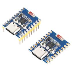
ESP32-H2-Zero
Overview
Introduction
ESP32-H2-Zero is a compact microcontroller development board with multiple digital interfaces.
In hardware, it adopts the ESP32-H2FH4S chip, which features a RISC-V 32-bit single-core processor with a clock frequency up to 96 MHz, and includes 320 KB SRAM, 128 KB ROM, and 4 KB LP memory. It is compatible with a variety of peripheral devices, making it more convenient to use.
On the software side, you can choose to develop in the ESP-IDF development environment or on the Arduino IDE, making it easy and quick to get started and apply it to products.
Features
- Adopts the ESP32-H2FH4S chip, equipped with a RISC-V 32-bit single-core processor, with a clock speed of up to 96 MHz
- Integrated 320 KB SRAM, 128 KB ROM, 4 KB LP memory, and 4MB Flash memory
- Integrated Bluetooth LE wireless communication and IEEE 802.15.4 technology, featuring superior RF performance
- Adopts Type-C connector, no need to worry about insertion direction
- Rich peripheral interfaces, compatible with the pins of ESP32-H2-DevKitM-1 development board, offers strong compatibility and expandability
- Castellated module allows soldering directly to carrier boards
- Support a variety of low-power operating states, adjustable balance between communication distance, data rate and power consumption to meet the power requirements of various application scenarios
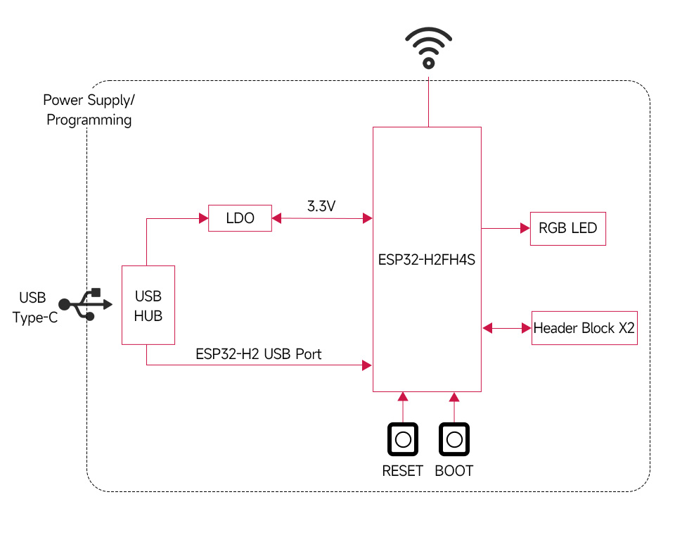
Functional Block Diagram
Interfaces
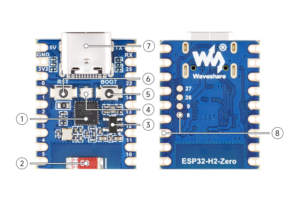
1. ESP32-H2FH4S 2. 2.4G ceramic antenna 3. ME6217C33M5G 4. WS2812 RGB LED | 5. BOOT button 6. RESET button 7. USB Type-C port 8. ESP32-H2FH4S pinout |
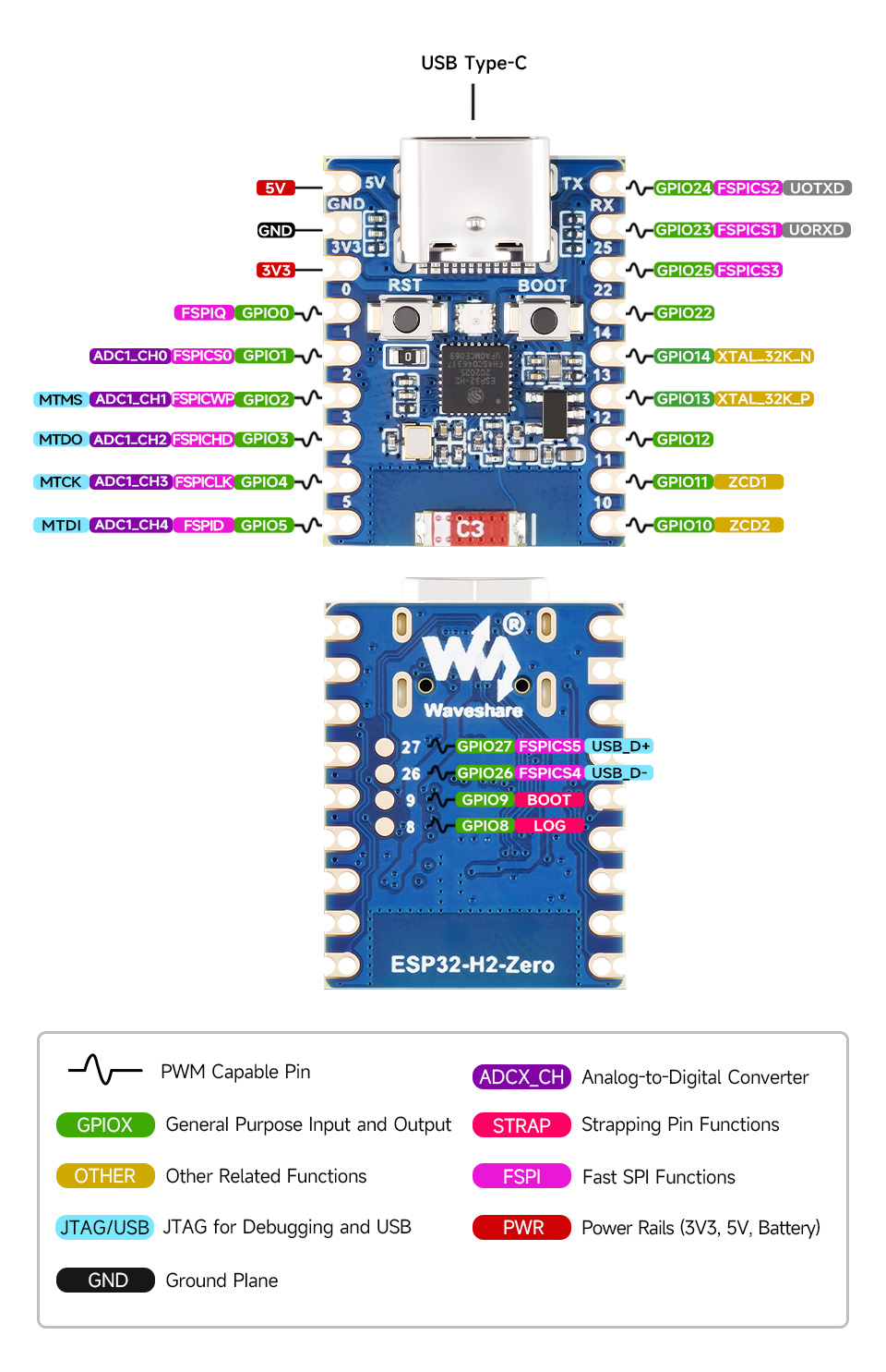
Pinout Definition
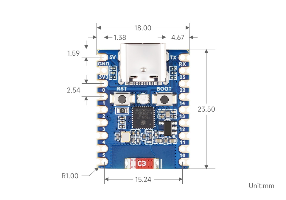
Dimensions
Working with ESP-IDF
The following development system is Windows by default, and it is recommended to use the VSCode plug-in for development.
Develop with VSCode Plug-in
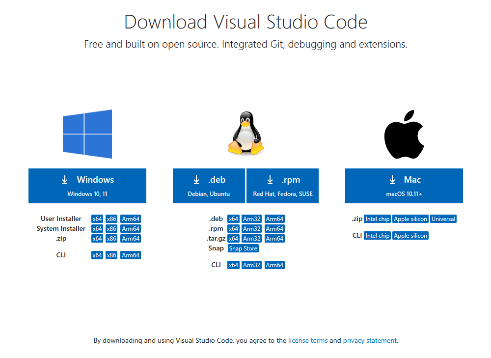
Install VSCode
- Open the download page of the official VSCode website, and select the corresponding system and system bit to download.
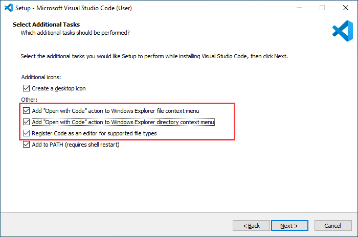
- After running the installation package, the rest can be installed by default, but here for the subsequent experience, it is recommended to check boxes 1, 2, and 3.
- After the first two items are enabled, you can open VSCode directly by right-clicking files or directories, which can improve the subsequent user experience.
- After the third item is enabled, you can select VSCode directly when you choose how to open it.
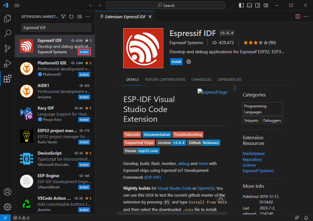
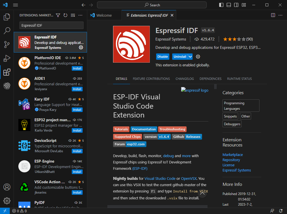
Install Espressif IDF Plug-in
- Note: Currently the latest version of the plugin is V1.6.4, users can choose the same version as us for a consistent experience.
- Open VSCode, use Shift+Ctrl+X enter the plug-in manager.
- In the search bar, enter Espressif IDF to select the corresponding plug-in and click Install.
- Press shortcut key F1 to input:
esp-idf: configure esp-idf extension
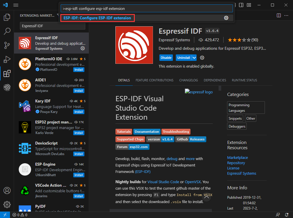
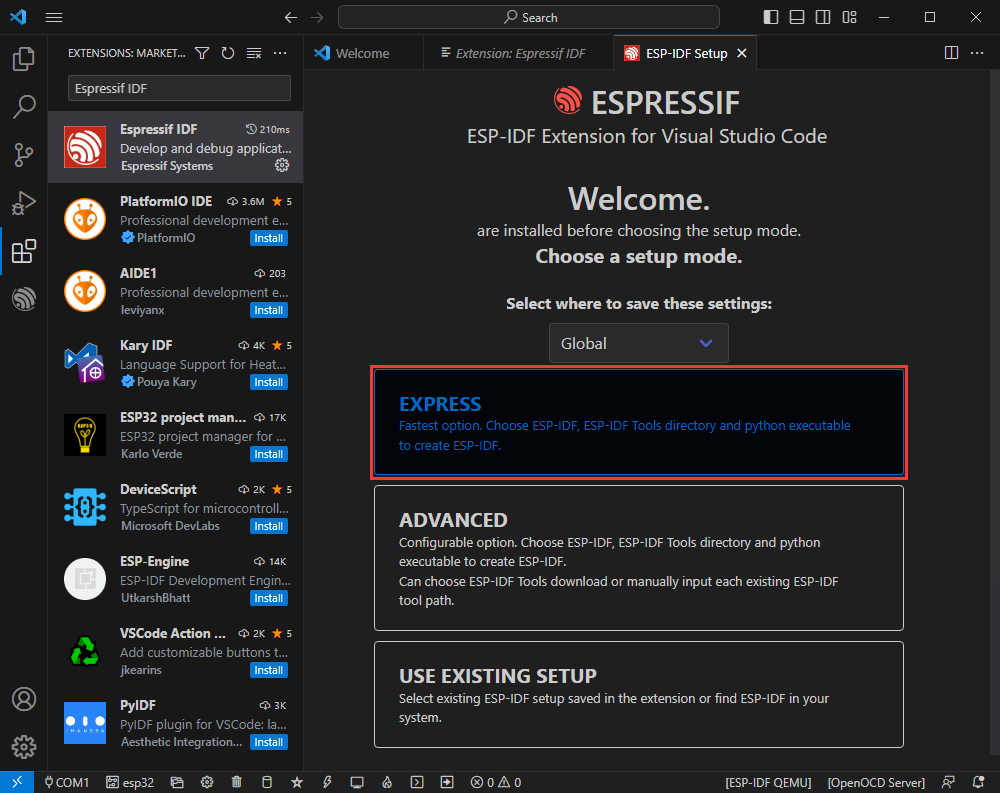
- Select express (This tutorial is intended for first-time installation users, so only the first general installation tutorial is covered).
- Choose the download server, we recommend users to use Espressif as your download server
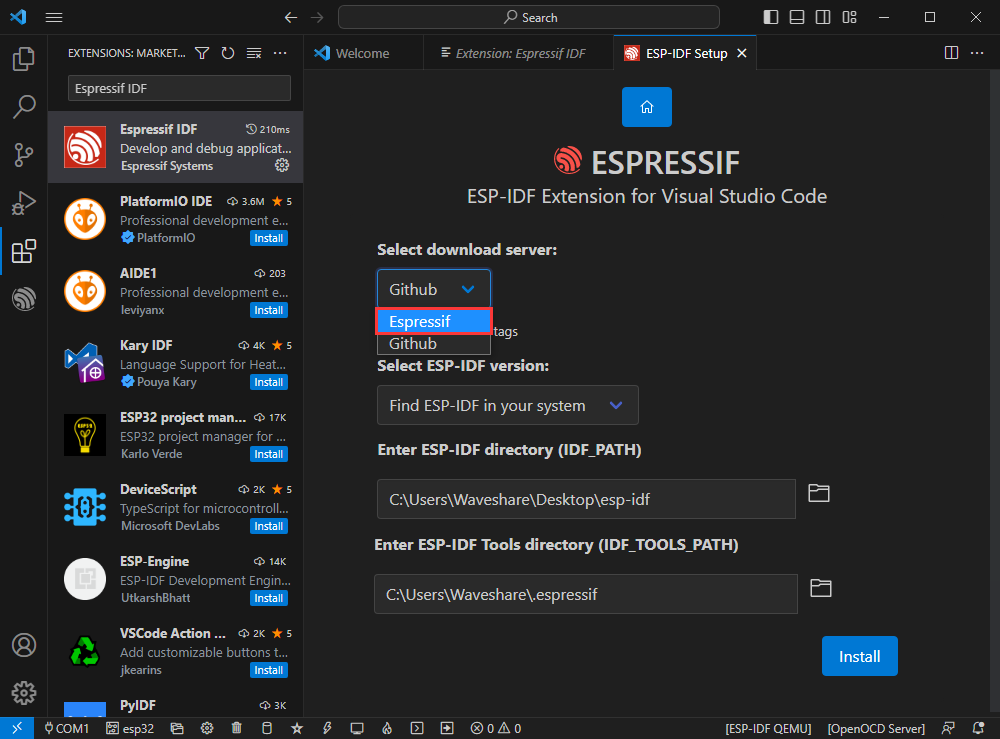
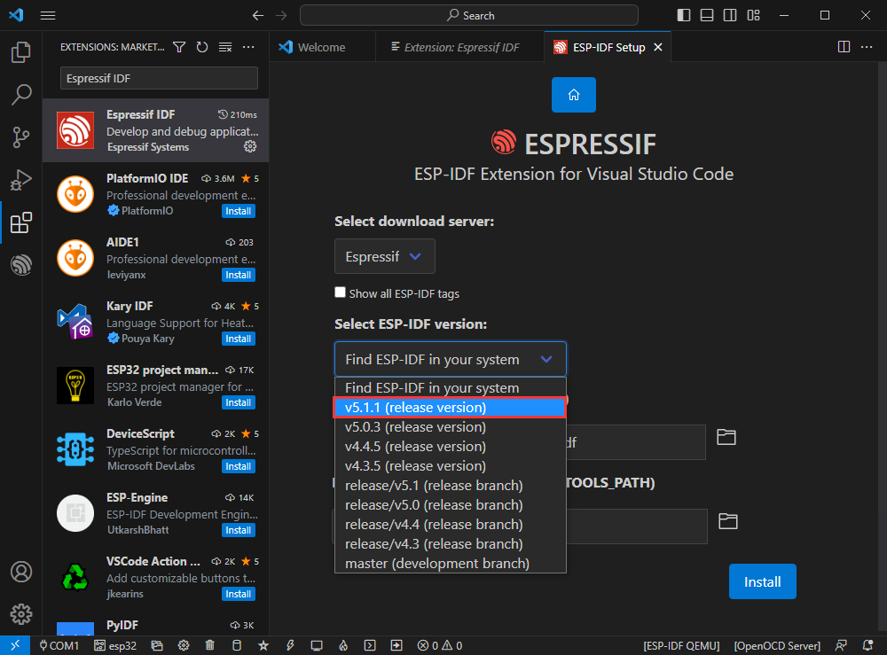
- Select the version of ESP-IDF you want to use now, we choose the latest V5.1.1 (note that ESP-IDF only supports ESP32-H2 after V5.1)
- The following two are the installation paths respectively for the ESP-IDF container directory and the ESP-IDF Tools directory.
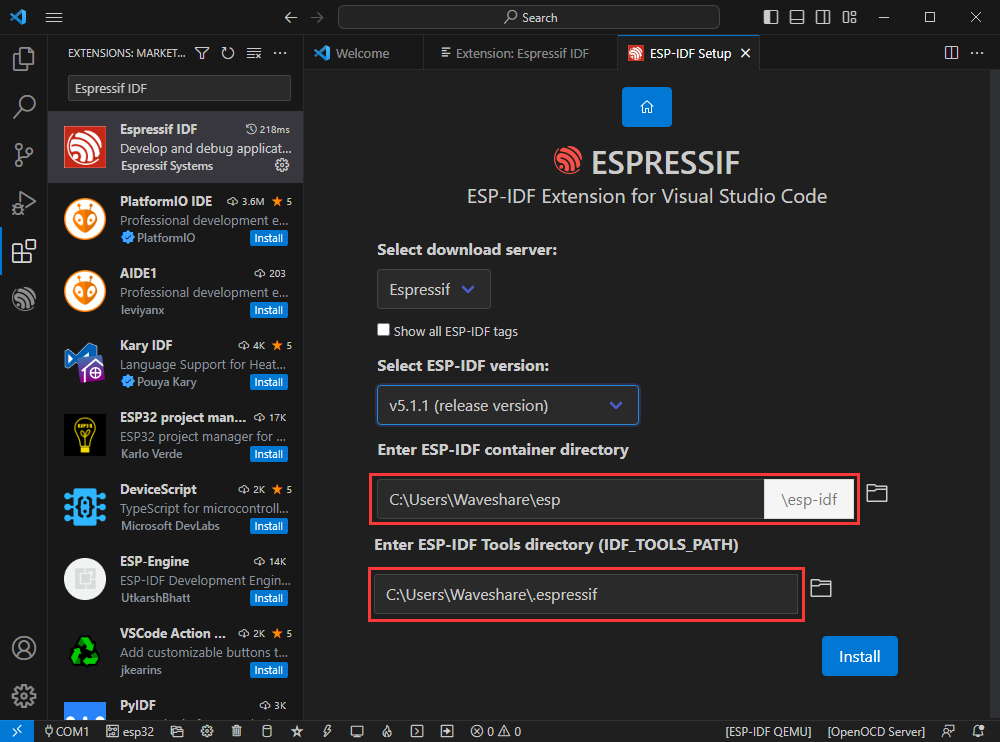
- Note: If you have installed ESP-IDF before, or failed to do so, please be sure to delete the file completely or create a new path without Chinese.
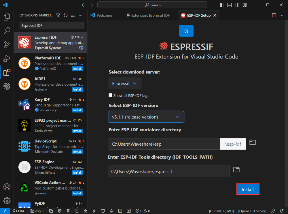
- After configuring, click Install to download:
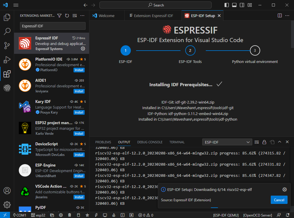
- Enter the download interface, and then it will automatically install the corresponding tools and environment, just wait for a second.
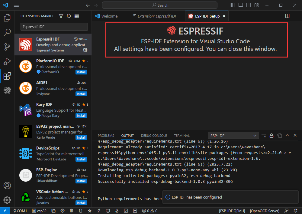
- After the installation is complete, you will enter the following interface, indicating that the installation is finished.
Official Demo Usage Tutorial
Create Demo ( Demo )
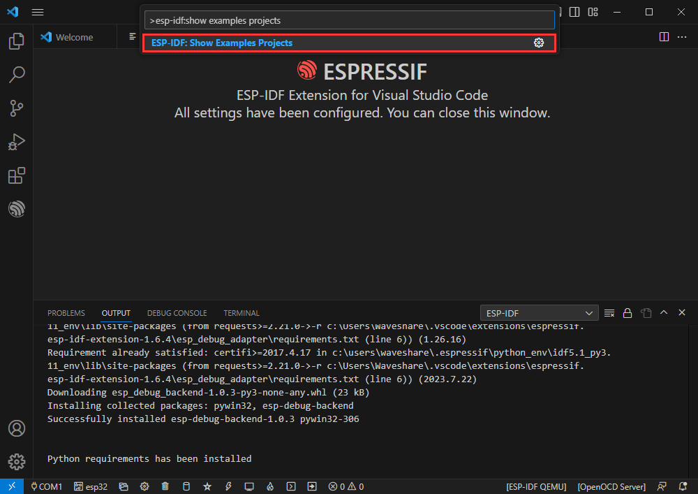
- Press shortcut key F1 to input:
esp-idf:show examples projects
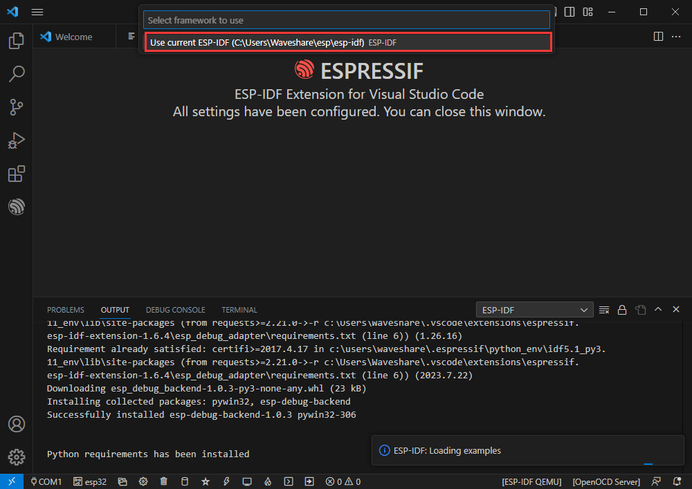
- Select your current IDF version
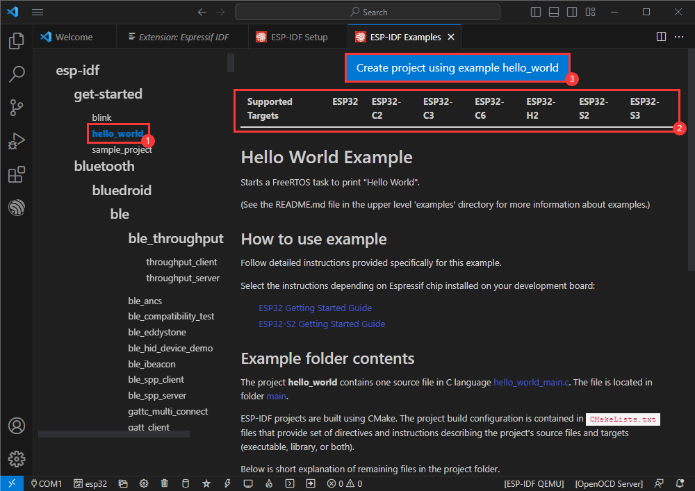
- Take the Hello world demo as an example:
- ①Select the corresponding demo.
- ②Its readme will state what chip the demo applies to (how to use the demo and the file structure are described below, omitted here).
- ③Click to create the demo.
Select the path to save the demo, and require that the demos cannot use folders with the same name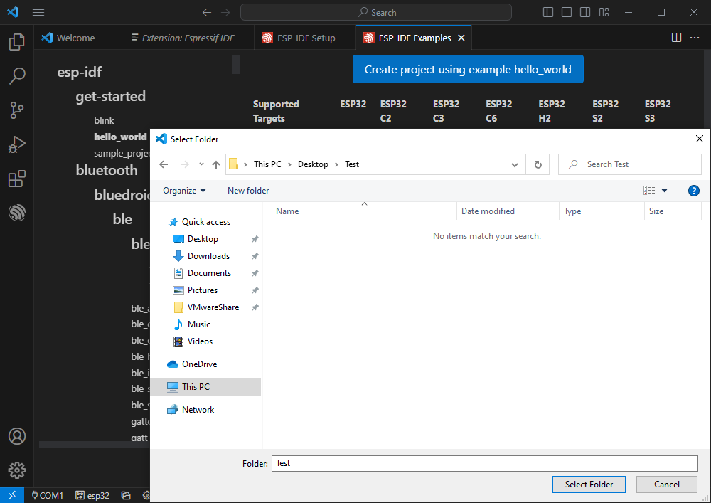
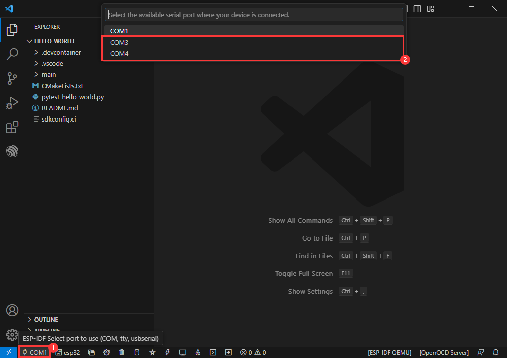
Modify COM Port
- The corresponding COM ports are shown here, click to modify them.
- Please select the COM ports corresponding to the device. It is recommended to prioritize using the COM port corresponding to USB (which can be viewed in Device Manager)
- If the download fails, please press and hold the Reset button for more than 1 second, and wait for the PC to re-recognize the device before downloading again.
- Select the project or demo to use.
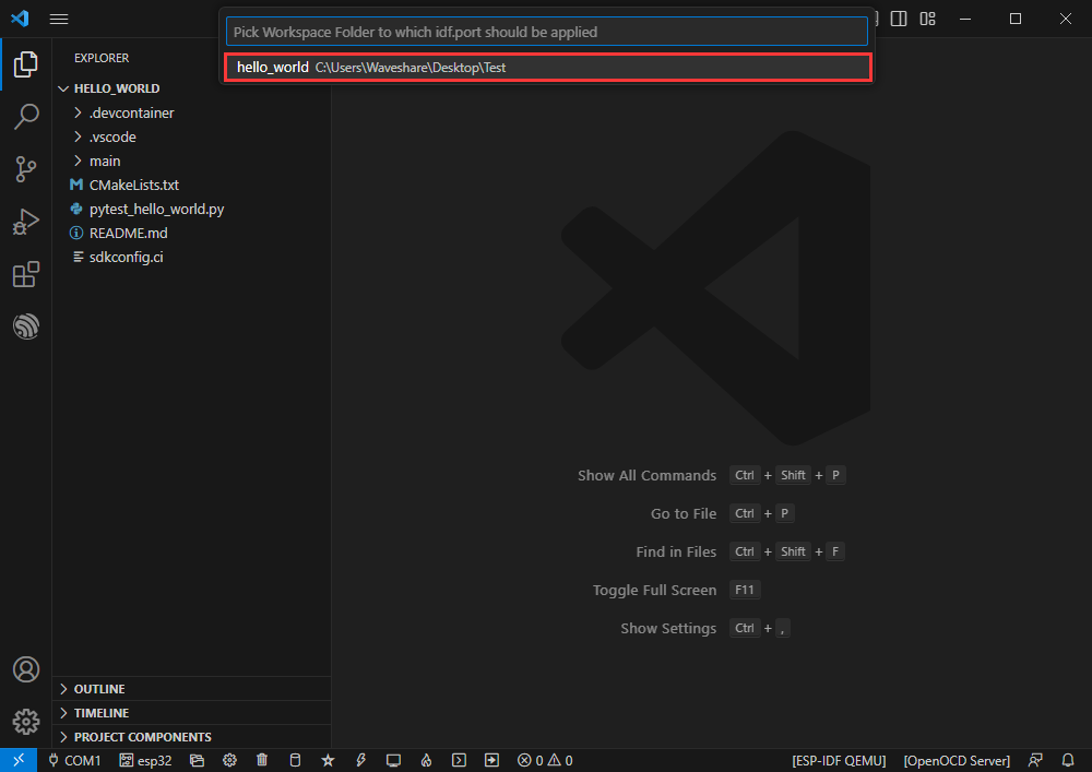
- Then we finish the modification of the COM ports.
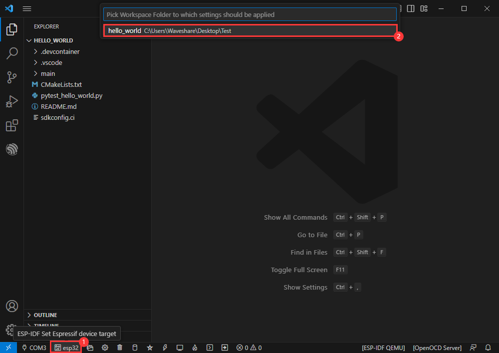
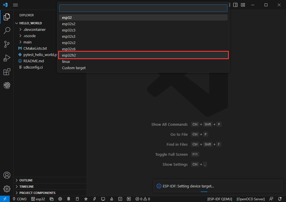
Modify Driver Object
- The driver object is displayed here, and you can modify it by clicking on it.
- Select the project or demo to use.

- Wait for a moment after clicking.
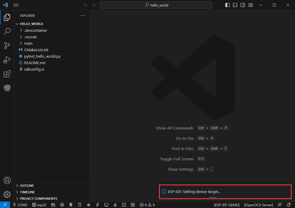
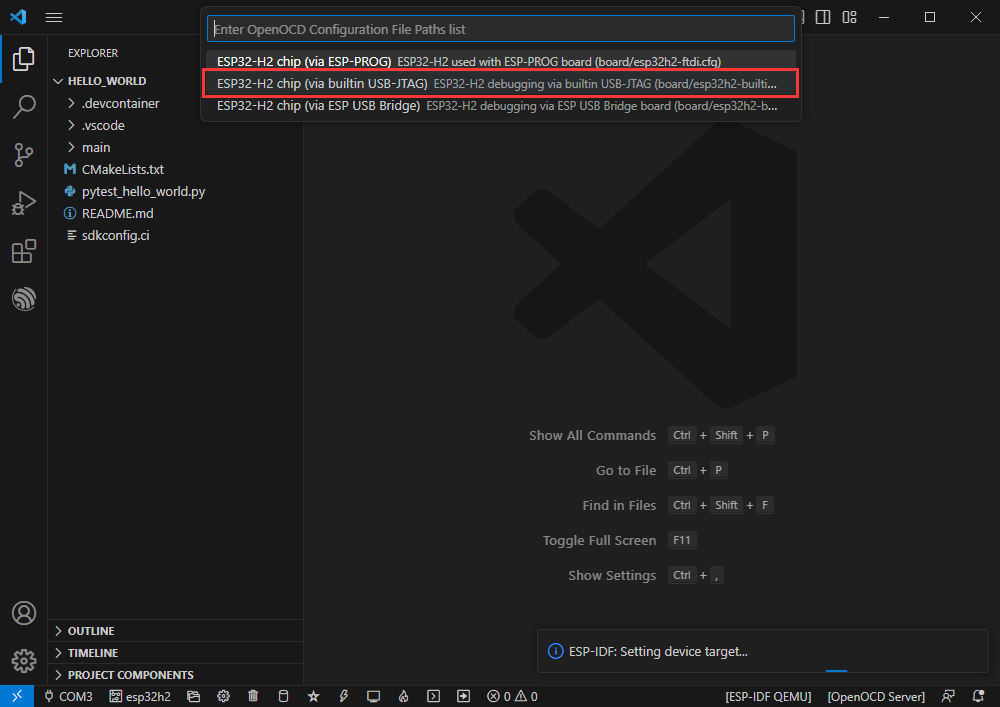
- Select the object we need to drive, which is our main chip ESP32H2

- Choose the openocd path, it doesn't affect us here, so let's just choose one.
Other Status Bar Functions
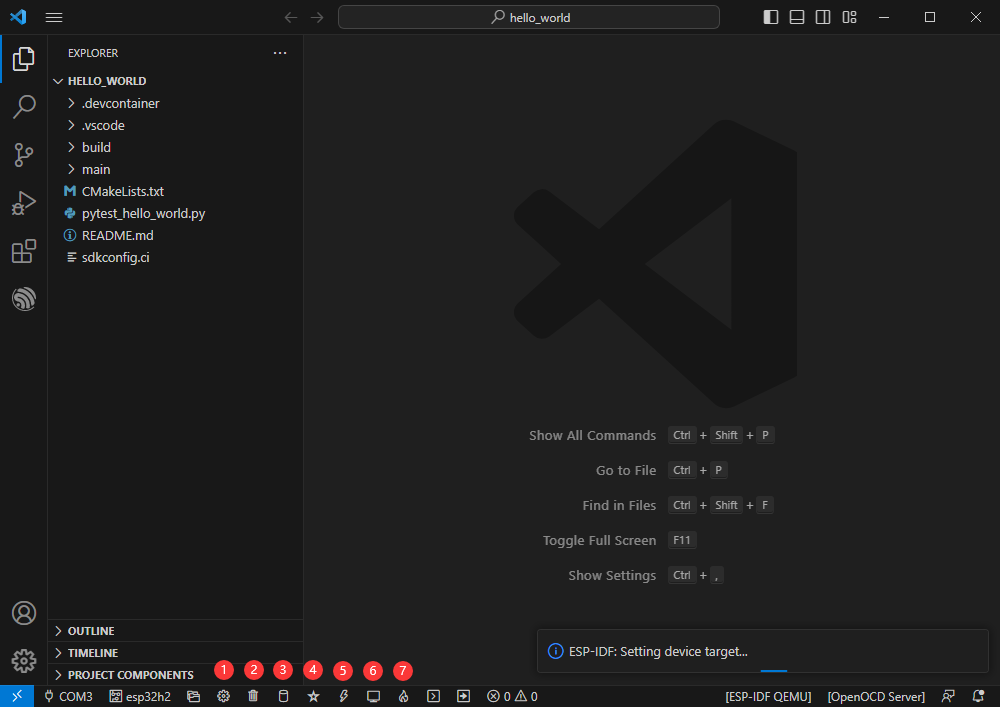
- ①SDK configuration editor, supports modifying many features and configurations of ESP-IDF
- ②All cleanup, and clear all compiled files
- ③Compile
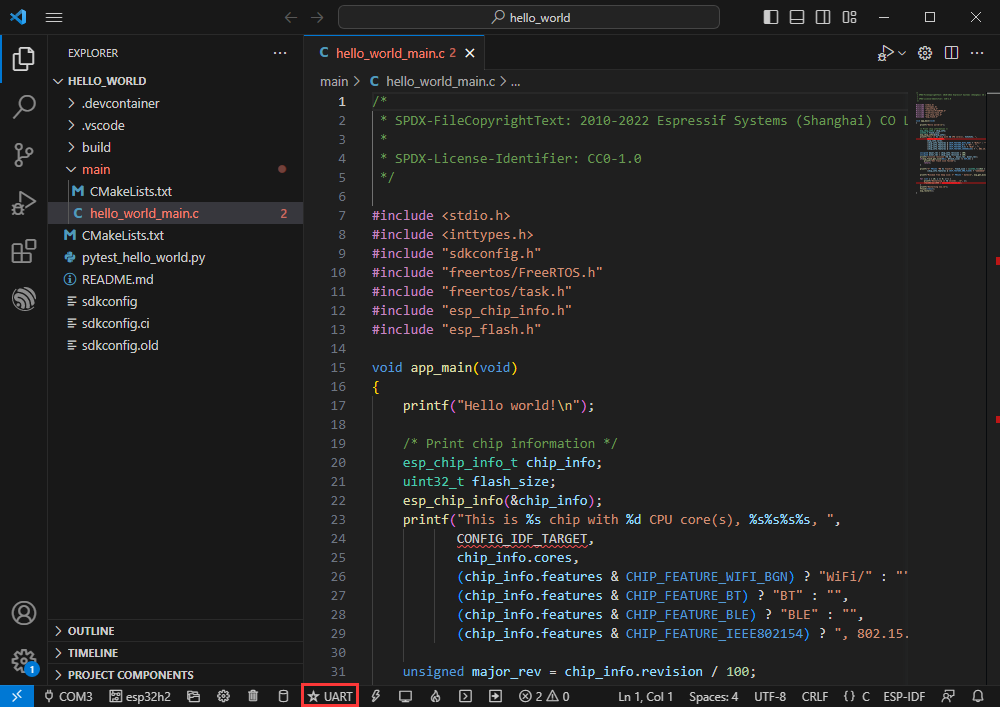
- ④Current download mode, the default is UART
- ⑤Flash the current firmware, please do it after compiling
- ⑥Open the serial port monitor, used to view the serial port information
- ⑦Compile, flash,open the serial monitor, all-in-one button (most commonly used for debugging)
Compile, Flash and Serial Monitor
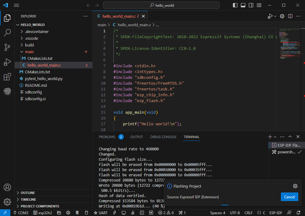
- Click on the all-in-one button we described before to compile, flash and open the serial monitor.
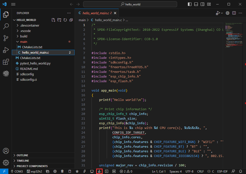
- It may take a long time to compile especially for the first time.
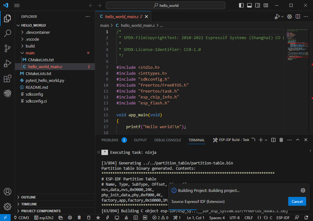
- During this process, the ESP-IDF may take up a lot of CPU resources, so it may cause the system to lag.
- If it is the first time to flash the program for a new project, you will need to select the download method, and select UART.
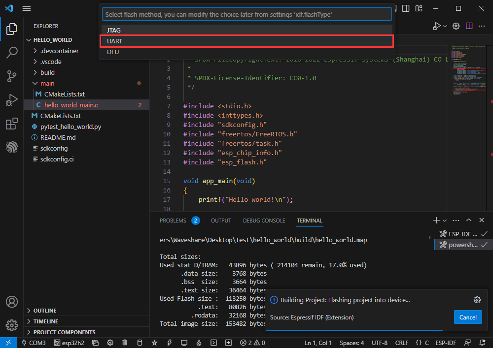
- This can also be changed later in the Download methods section (click on it to bring up the options).
- As it comes with the onboard automatic download circuit, it can be downloaded automatically without manual operation.
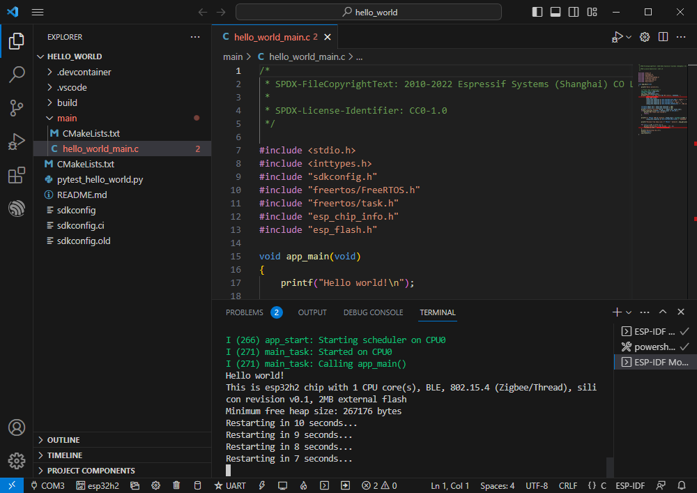
- After successful download, it will automatically enter the serial monitor, you can see the chip output the corresponding information and be prompted to restart after 10S
Demo Demonstration
Hello Word
- Official demo path: get-started -> hello_world
- Demo effect: Output Hello world! at 10-second intervals in the TERMINAL window
Software Operation
- Create the official demo hello_world according to the tutorial (Create Demo) above
- The demo is compatible with ESP32-H2 and can be used without modifying the demo
- Modify the COM port and driver object (it is recommended to use the COM port corresponding to USB, which can be viewed in Device Manager) and click compile and flash to run the program

GPIO
- Official demo path: peripherals -> gpio -> generic_gpio
- Demo effect: LED flashes at 1-second intervals
Hardware Connection
ESP32-H2 LED GPIO18 (or GPIO19) LED+ GND LED-
Software Operation
- Create the official demo generic_gpio according to the tutorial (Create Demo) above
- The demo is compatible with ESP32-H2 and can be used without modifying the demo
- Modify the COM port and driver object (it is recommended to use the COM port corresponding to USB, which can be viewed in Device Manager) and click compile and flash to run the program
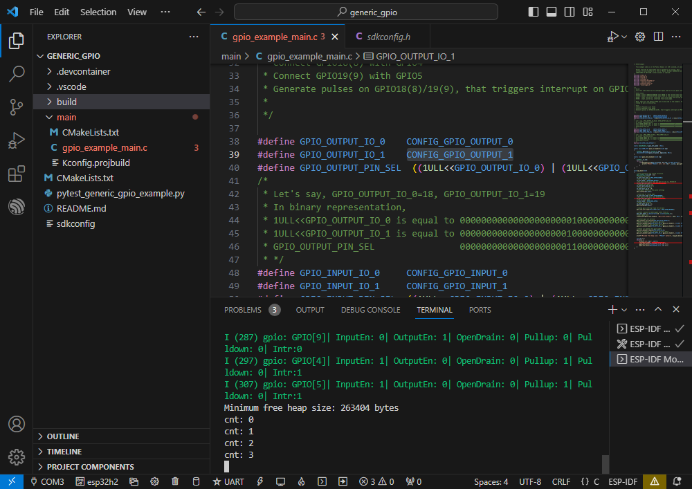
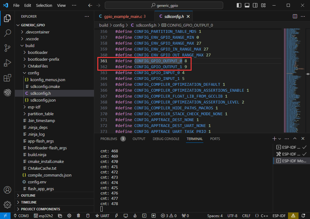
- Enter demo macro definition location to see the GPIO actually processed
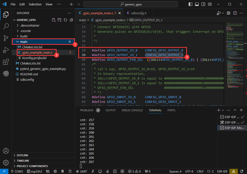
- Right-click to enter GPIO definition location
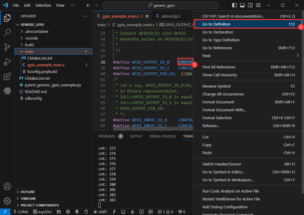
- The GPIOs actually processed are GPIO8 and GPIO9
RGB
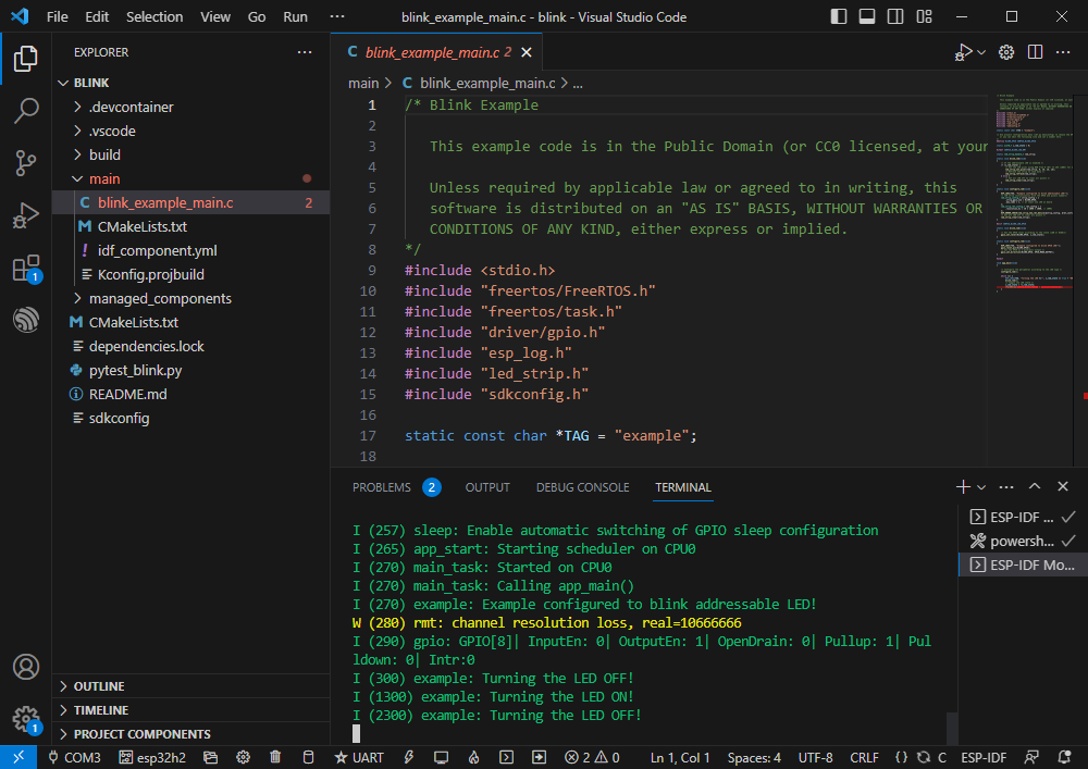
- Official demo path: get-started -> blink
- Demo effect: Onboard RGB light beads blink at 1-second intervals
Software Operation
- Create the official demo blink according to the tutorial (Create Demo) above
- The demo is compatible with ESP32-H2 and can be used without modifying the demo
- Modify the COM port and driver object (it is recommended to use the COM port corresponding to USB, which can be viewed in Device Manager) and click compile and flash to run the program
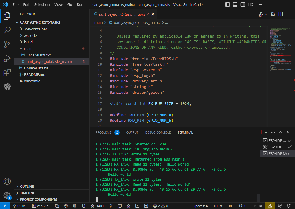
UART
- Official demo path: peripherals -> uart-> uart_async_rxtxtasks
- Demo effect: Perform UART data self-transmission/reception by shorting GPIO4 with GPIO5
Hardware Connection
ESP32-H2 ESP32-H2 (same chip) GPIO4 GPIO5
Software Operation
- Create the official demo uart_async_rxtxtasks according to the tutorial (Create Demo) above
- The demo is compatible with ESP32-H2 and can be used without modifying the demo
- Modify the COM port and driver object (it is recommended to use the COM port corresponding to USB, which can be viewed in Device Manager) and click compile and flash to run the program
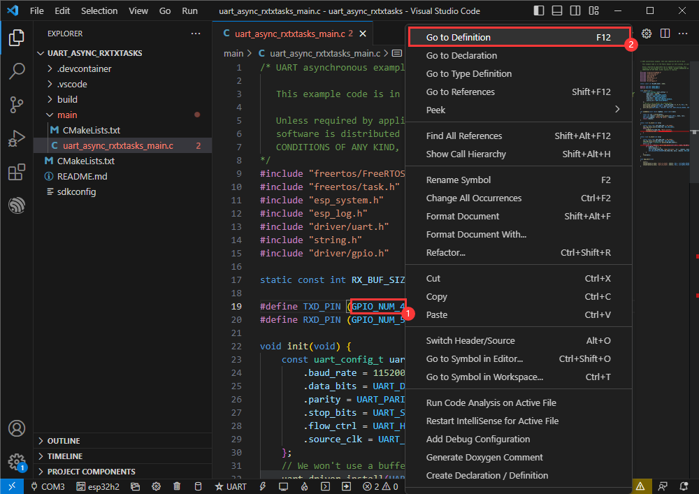
- Connect hardware based on the GPIO used
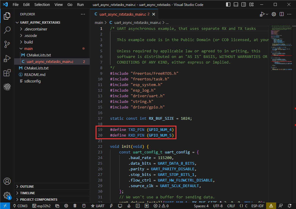
- Go to the definition file to see the GPIO actually used (check GPIO_NUM_4 -> right click -> Go to Definition)
I2C
- Official demo path: peripherals -> lcd-> i2c_oled
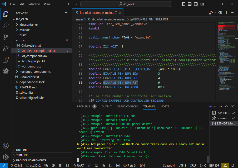
- Demo effect: Light up 0.96inch OLED (A) and display a string of characters
Hardware Connection
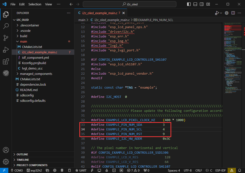
0.96inch OLED (A) ESP32-H2 VCC 3V3 GND GND DIN GPIO3 CLK GPIO4 CS GND D/C GND RES GPIO9
Software Operation
- Create the official demo i2c_oled according to the tutorial (Create Demo) above
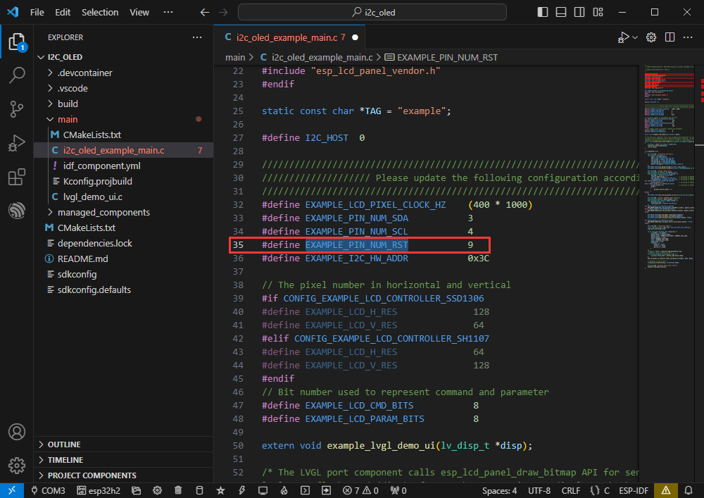
- Modify the demo to be compatible with 0.96inch OLED (A)
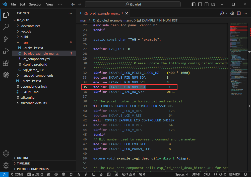
- Adapt to 0.96inch OLED (A), define the RES pin as GPIO9
- Modify the COM port and driver object (it is recommended to use the COM port corresponding to USB, which can be viewed in Device Manager) and click compile and flash to run the program
- View the GPIO actually used
SPI
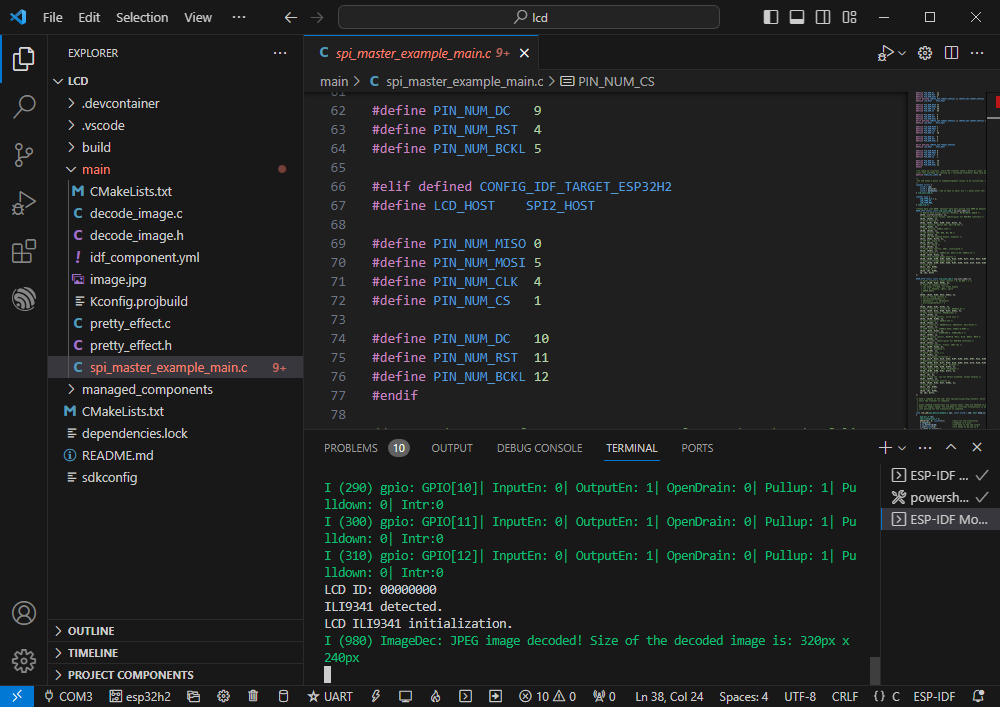
- Official demo path: peripherals -> spi_master-> lcd
- Demo effect: Display images dynamically on the 2.4inch LCD Module
Hardware Connection
2.4inch LCD Module ESP32-H2 VCC 3V3 GND GND DIN GPIO5 CLK GPIO4 CS GPIO1 D/C GPIO10 RES GPIO11 BL GPIO12
Software Operation
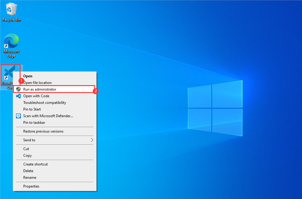
- Right-click on the VScode icon to run VScode as an administrator
- Create the official demo lcd according to the tutorial (Create Demo) above
- Modify the demo to be compatible with 2.4inch LCD Module
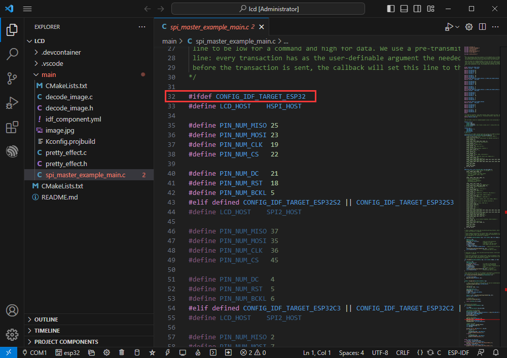
- Jump to the defined location
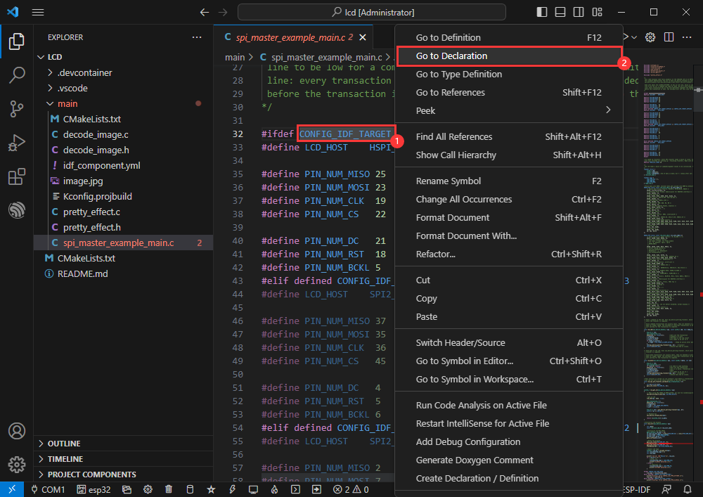
- The ESP32-H2 is currently in use, block other chip definitions
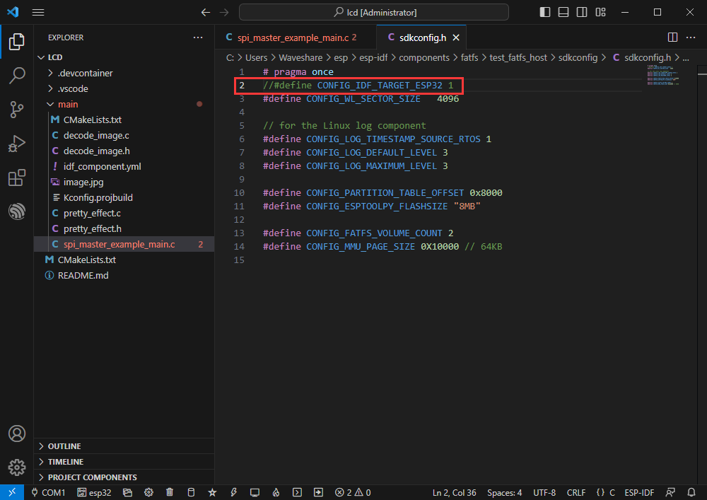
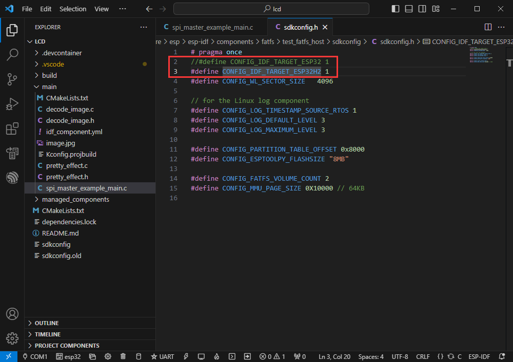
- Define the macro ESP32-H2, CONFIG_IDF_TARGET_ESP32H2
//#define CONFIG_IDF_TARGET_ESP32 1
#define CONFIG_IDF_TARGET_ESP32H2 1
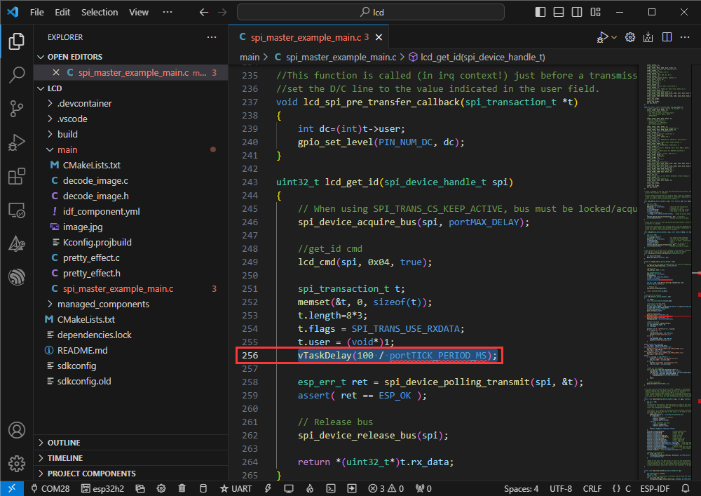
- Waiting to read ID
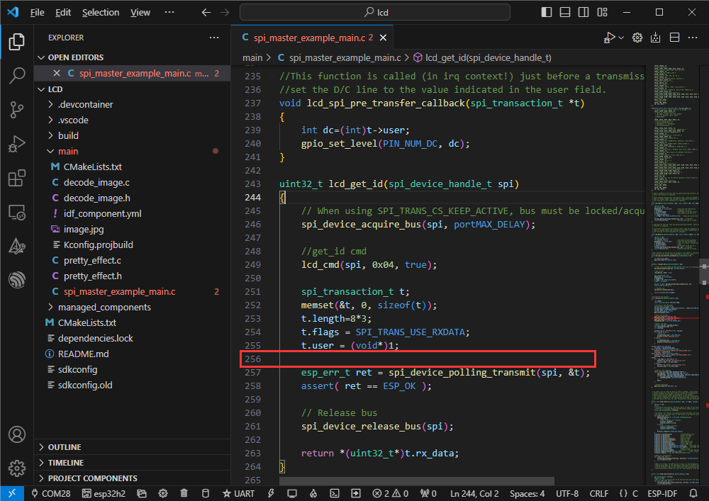
- Add read delay to prevent read failure
vTaskDelay(100 / portTICK_PERIOD_MS);
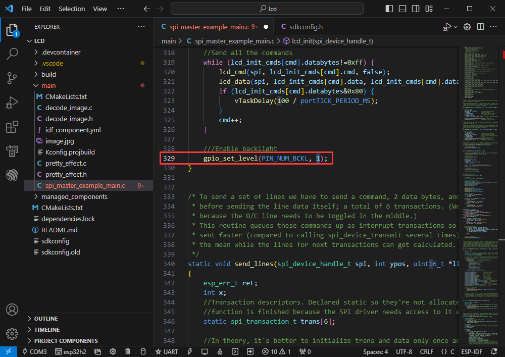
- Modify the backlight
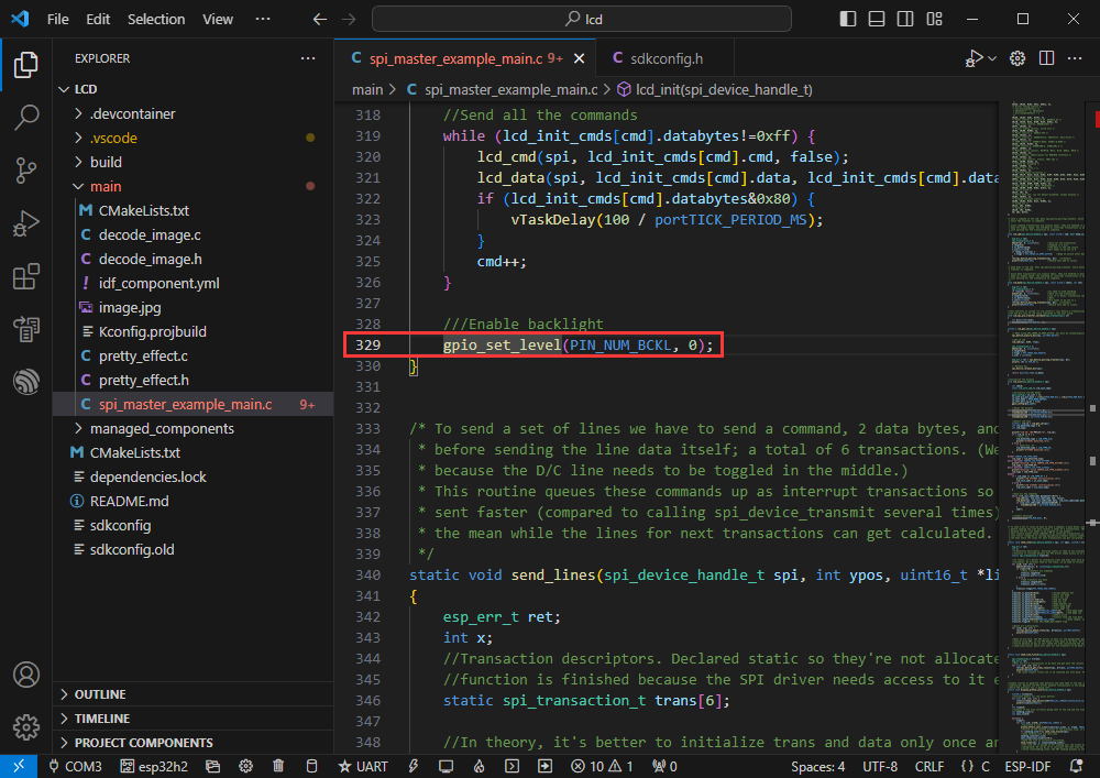
- Changed to gpio_set_level(PIN_NUM_BCKL, 1);
- Modify the COM port and driver object (it is recommended to use the COM port corresponding to USB, which can be viewed in Device Manager) and click compile and flash to run the program
Bluetooth
- Official demo path: bluetooth -> bluedroid -> ble -> gatt_server
- Demo effect: ESP32-H2 transmits data with the Bluetooth debugging assistant on the mobile phone
Software Operation
- Install Bluetooth debugging assistant on the mobile phone (other Bluetooth debugging software can also be used)
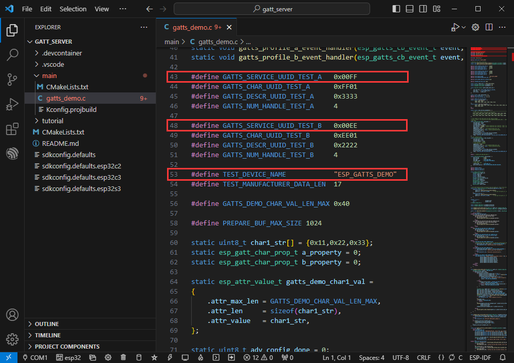
- Create the official demo gatt_server according to the tutorial (Create Demo) above
- The demo is compatible with ESP32-H2 and can be used without modifying the demo
- Bluetooth name and UUID, Bluetooth name is ESP_GATTS_DEMO
- Modify the COM port and driver object (it is recommended to use the COM port corresponding to USB, which can be viewed in Device Manager) and click compile and flash to run the program
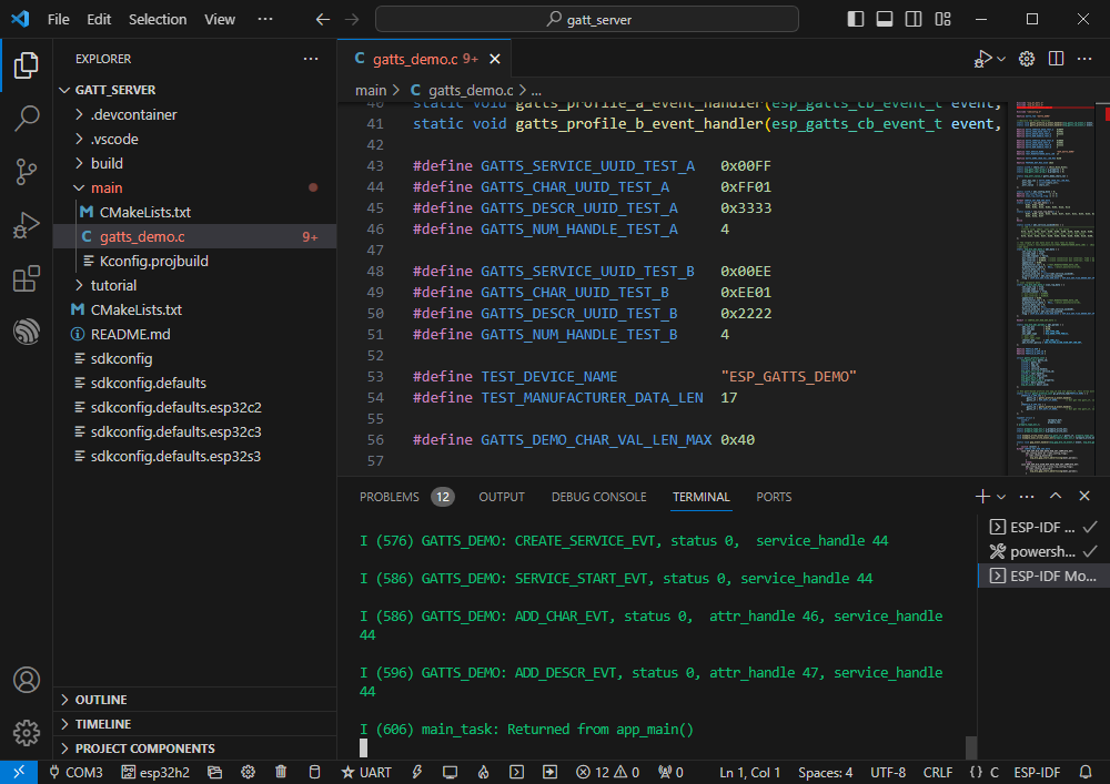
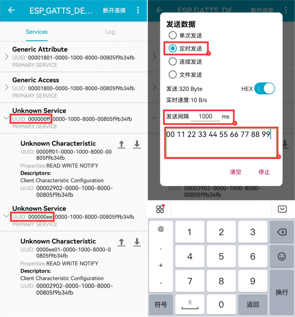
- Connect the Bluetooth device ESP_GATTS_DEMO on the mobile phone
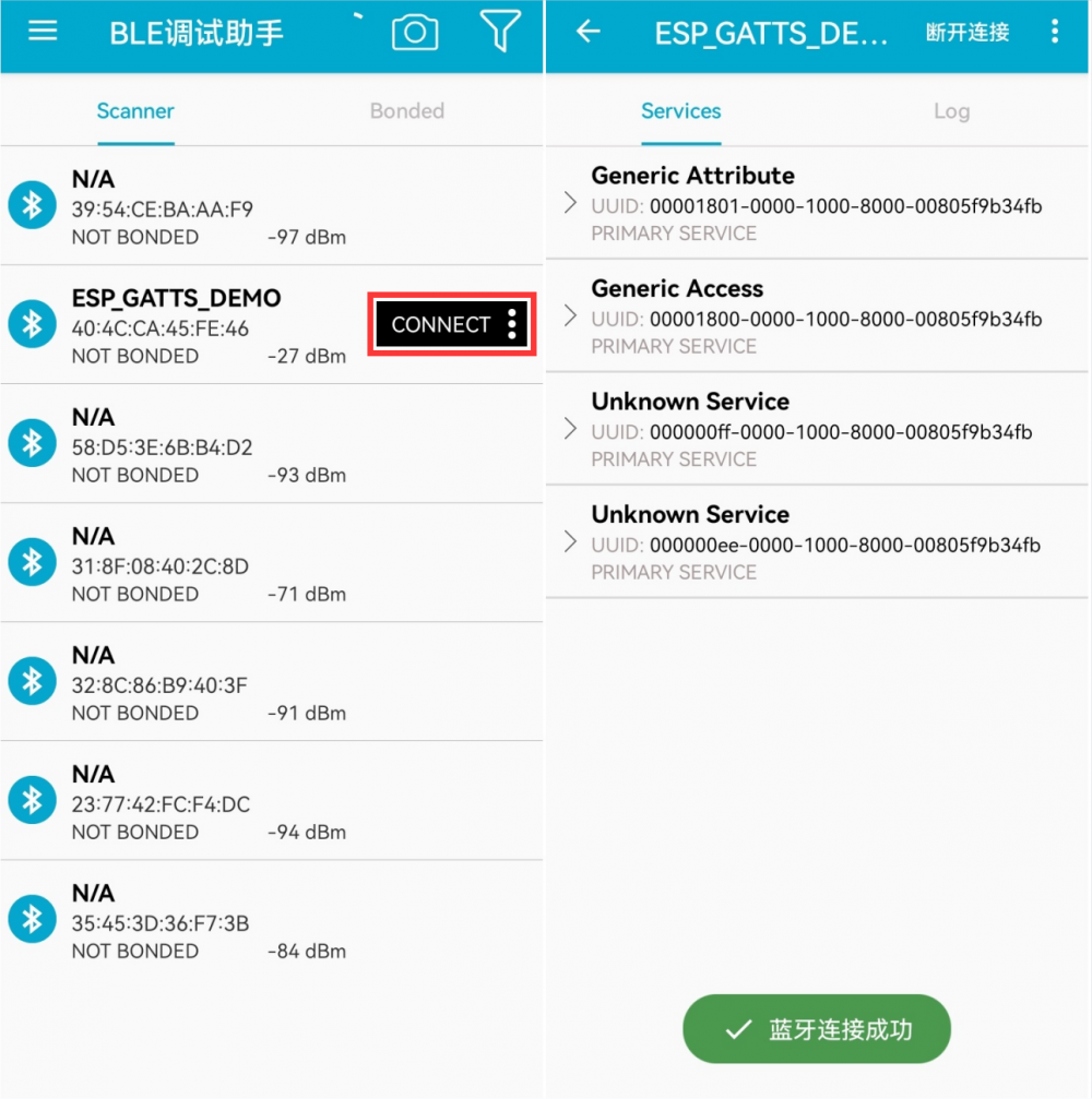
- The successful connection is shown below:
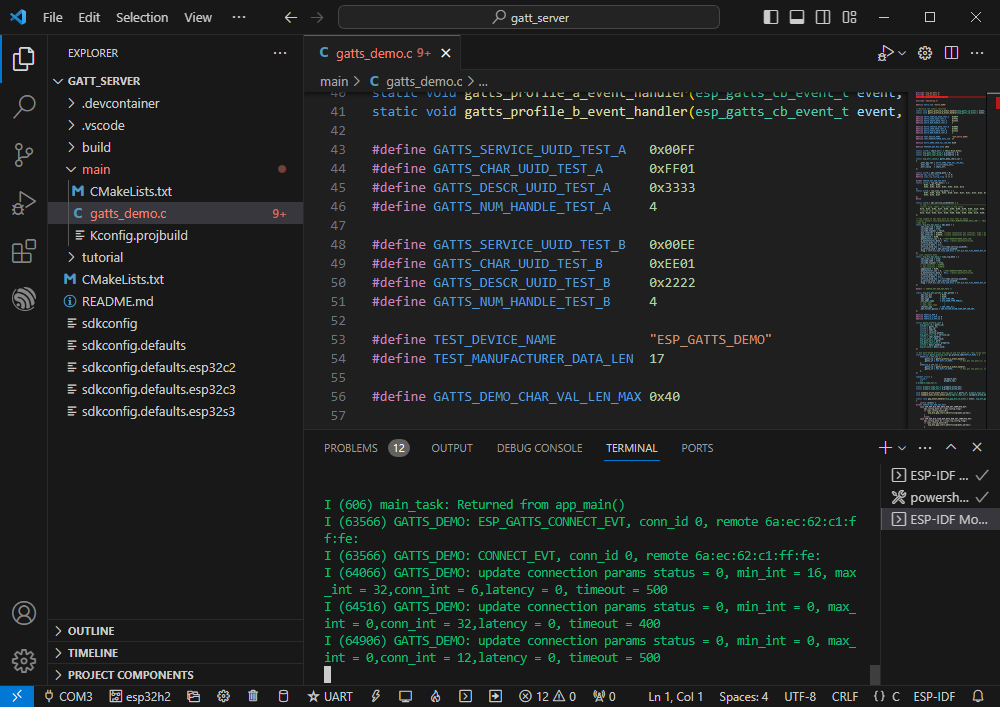
- Based on the value of the UUID in the program, it can be known that there are two servers below. Choose one for uplink transmission
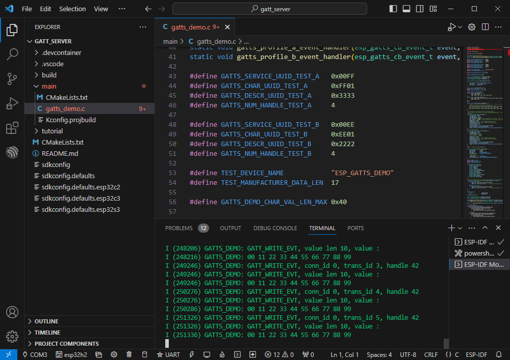
- ESP32-H2 receives data
Zigbee
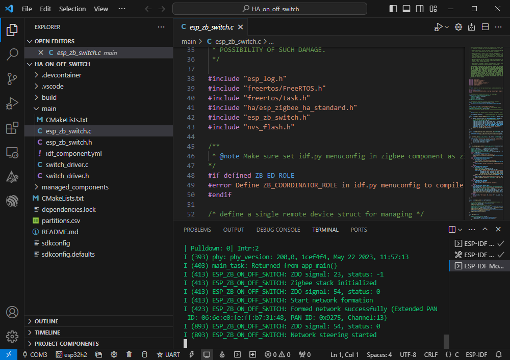
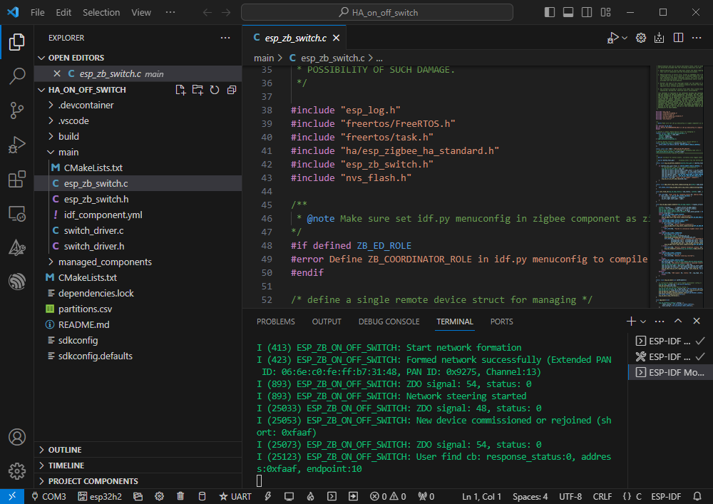
- Official demo 1 path: Zigbee-> light_sample-> HA_on_off_switch
- Official demo 2 path: Zigbee-> light_sample-> HA_on_off_light
- Demo effect: Two ESP32-H2 chips, use the BOOT button of one (to flash HA_on_off_switch demo) to control the on/off of the RGB LED on the other chip
- Note: Please flash the HA_on_off_switch demo to one chip first, and then flash HA_on_off_light demo to the other chip
Software Operation 1
- Create the official demo HA_on_off_switch according to the tutorial (Create Demo) above
- The demo is compatible with ESP32-H2 and can be used without modifying the demo
- Modify the COM port and driver object, click compile and flash to run the demo
Software Operation 2
- Create the official demo HA_on_off_light according to the tutorial (Create Demo) above
- The demo is compatible with ESP32-H2 and can be used without modifying the demo
- Modify the COM port and driver object, click compile and flash to run the demo (You need to wait for a while to allow the two chips to establish a connection)
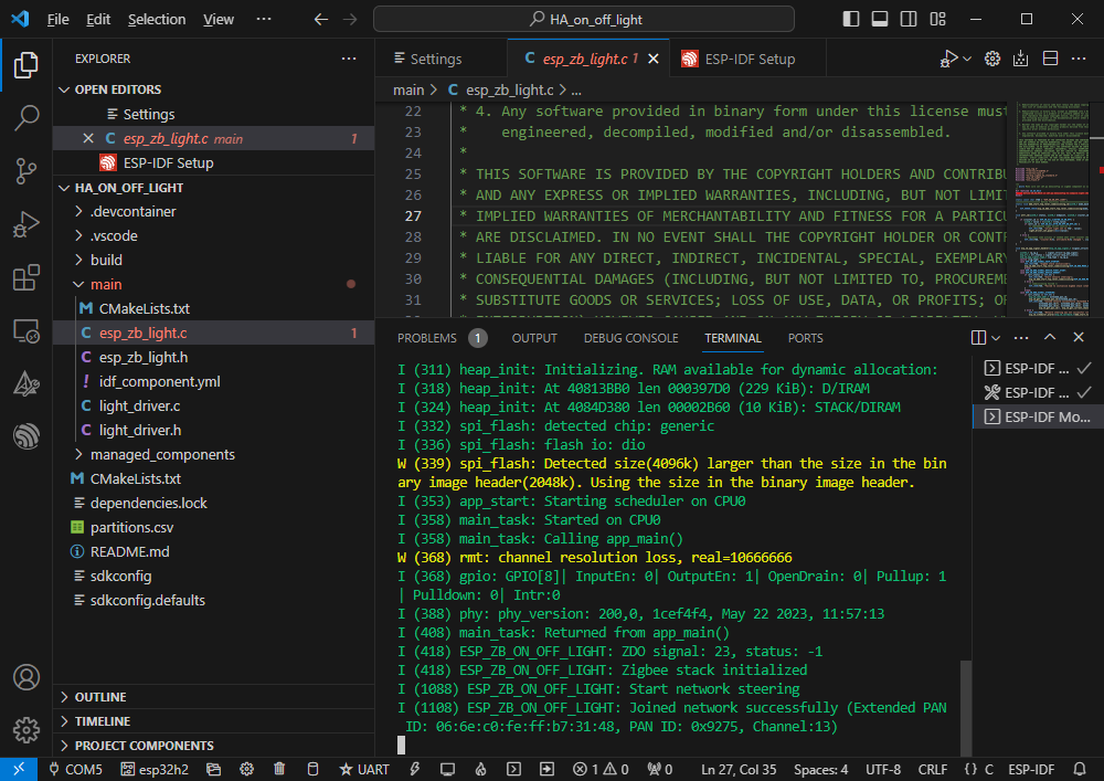
- If the connection is successful, the corresponding button demo and LED demo will print the relevant data
- If initialization fails, it may be due to the device having residual information from other networks. You can erase the device information (see Erasure Tutorial) and then re-network.
Flash Erasure Tutorial
- Unzip the software resource package (Flash debugging software)
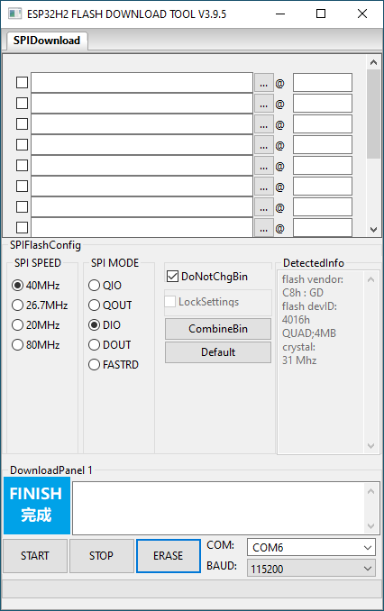
- Open flash_download_tool_3.9.5.exe software, select ESP32-H2 and UART
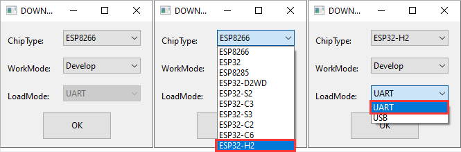
- Select the port number of the UART, click START (do not select any bin files)
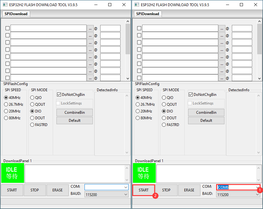
- Wait for the flashing to complete, then click Erase
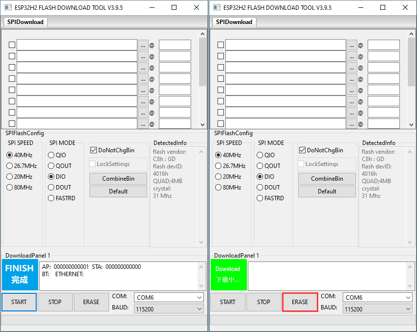
- Wait for the erasing to complete
Working with Arduino
Please note that Arduino 3.0.0-alpha is based on ESP-IDF v5.1 and differs significantly from versions based on ESP-IDF V4.X. After performing the following operations, your previous demo may require some adjustments to work properly
Please note that the computer username must be in English
Environment Setup
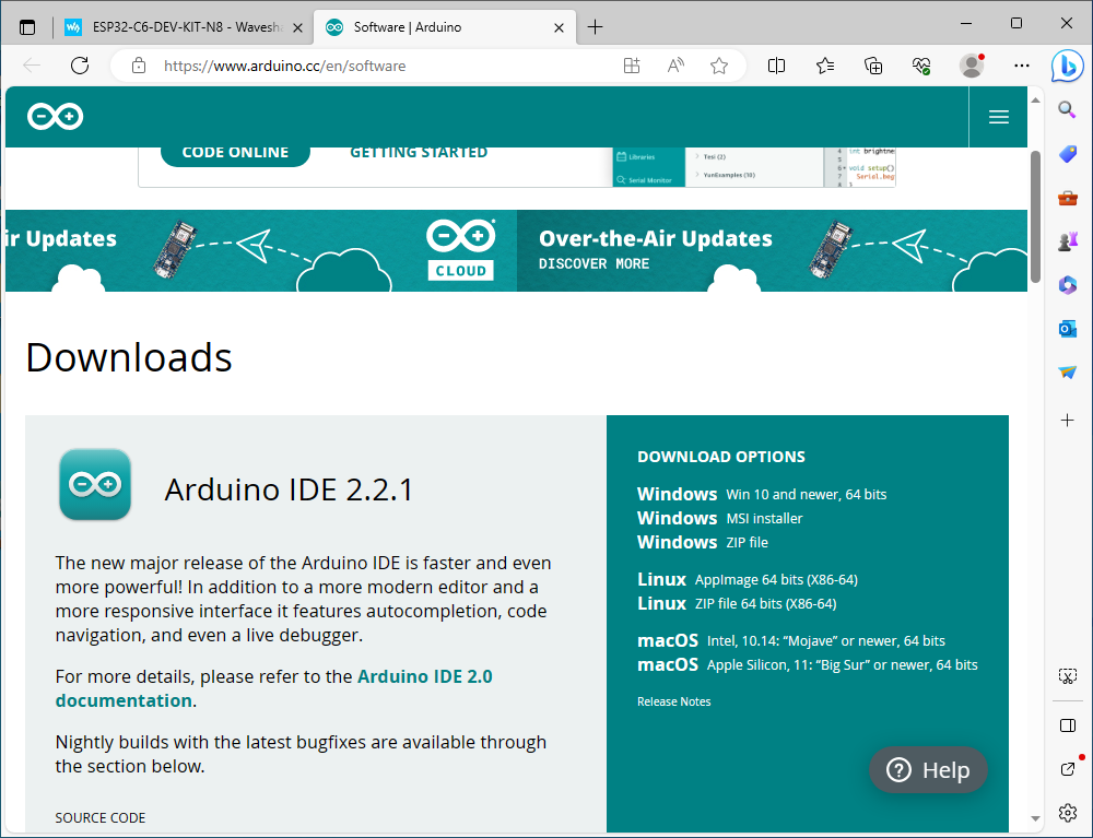
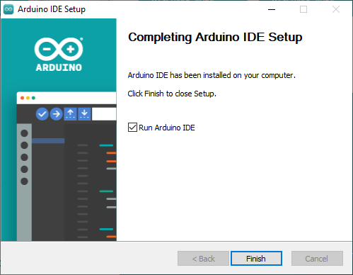
- Install Arduino IDE
- Open Arduino IDE after installation
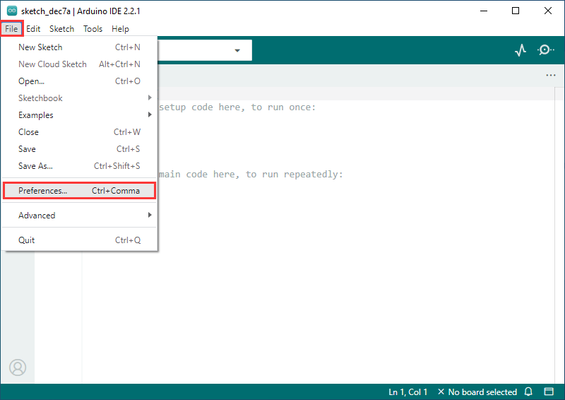
- Enter Preferences page
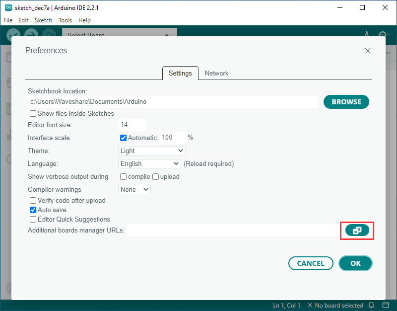
- Add a JSON link
https://espressif.github.io/arduino-esp32/package_esp32_dev_index.json
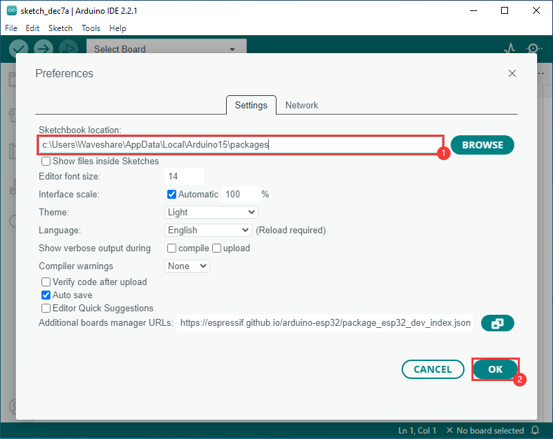
- Modify the project folder to C:\Users\Waveshare\AppData\Local\Arduino15\packages (where Waveshare is the computer username)
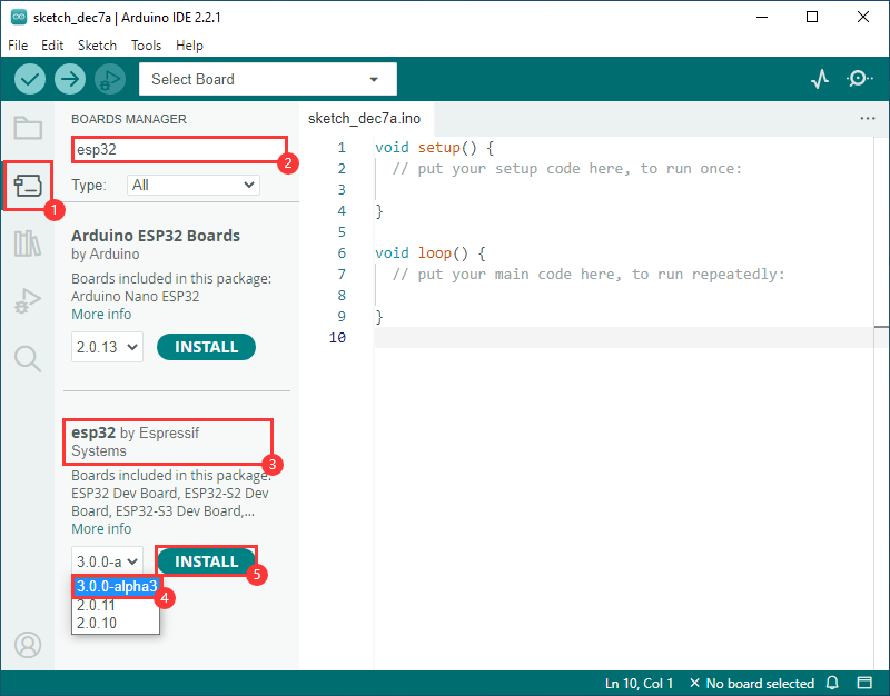
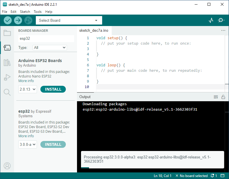
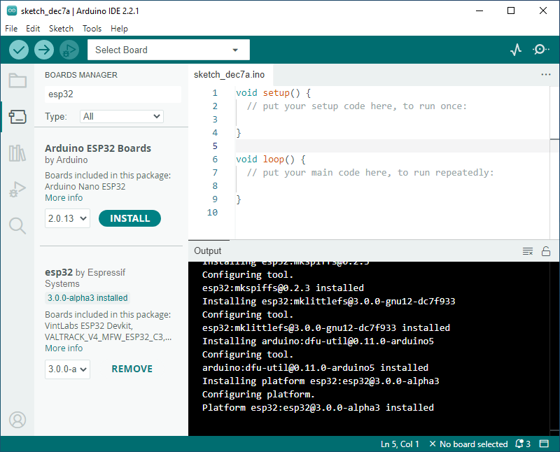
- Enter the development board manager, search for esp32, select 3.0.0-alpha3 version 3.0.0 in esp32 by Espressif Systems below, and click INSTALL (if it cannot be installed normally, you can try using a phone hotspot)
- Restart Arduino IDE after installation
Click to expand if installation fails
Create Demo
- Change the project folder above to c:\Users\Waveshare\AppData\Local\Arduino15\packages
- Create a demo based on the demos in the project folder under the file
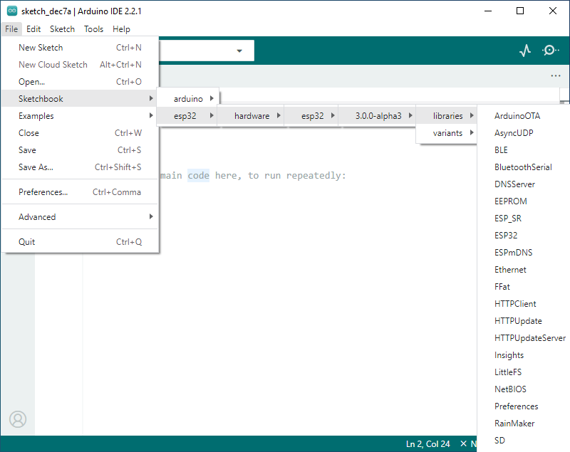
- The following demonstrates an example of creating an RGB blink (found under File -> Sketchbook -> esp32 -> hardware -> esp32 -> 3.0.0-alpha3 -> libraries -> ESP32 -> examples -> GPIO -> BlinkRGB )

- Select development board and port
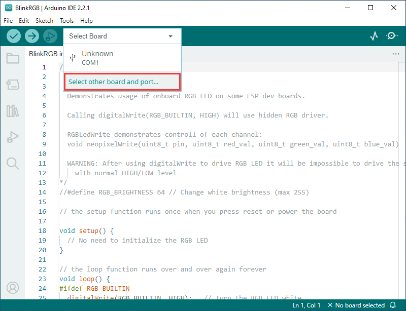
- Search for ESP32H2, select ESP32H2 Dev Module and download port
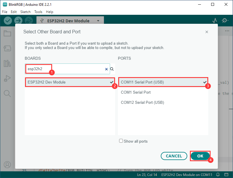
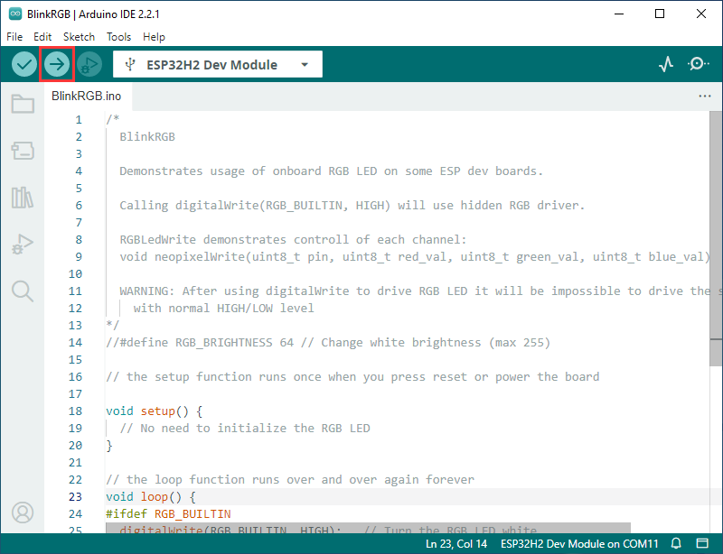
- Select OK, click upload, Arduino IDE will compile and flash the demo
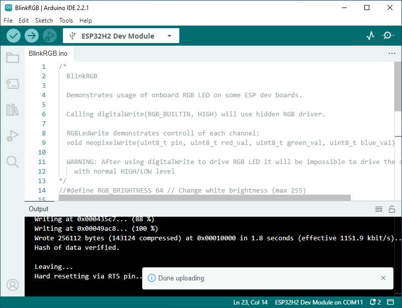
- Upload complete, and you can see the output on the development board
Resources
Software
Programming Software
Driver
Serial Port
Flashing
Bluetooth Debugging
Schematic Diagram
Datasheets
ESP32-H2
Official Document
Raspberry Pi Official Document
FAQ
Question: When compiling, it prompts that compilation failed and the specified file cannot be found. What should I do?
Please reselect the driver object and compile again.
Question: After the module downloads the demo and re-downloads it, why sometimes it can't connect to the serial port or the flashing fails?
Method 1: Click the Reset button for more than 1 second, wait for the PC to re-recognize the device and then download again.
Method 2: Long press the BOOT button, press RESET at the same time, then release RESET, then release the BOOT button, at this time the module can enter the download mode, which can solve most of the problems that can not be downloaded.
Question: When setting up the environment or project, there is no ESP option below. What should I do?
Click the shortcut key F1 in VSCode, search for Espressif IDF, and you will find the extension that is marked as untrusted. Set it to trusted.
Question: When switching to the same ESP, the flashing program appears. Is it a failure during program running?
Please re-select the COM port and the driver object after switching ESP, then recompile and flash.
Question: After powering on the module, the recognized serial port device keeps resetting and rebooting?
Check if the power voltage of the USB port is less than 5V. Generally, the power voltage of the USB port is above 4.9V, and both USB ports of the module can be used normally. If it is below 4.9V, there may be a power supply shortage and USB disconnection issue. In this case, a USB port with sufficient voltage should be used.
Question: When initializing the official Zigbee demo, an initialization failure occurs. How to deal with it?
It may be due to the device having residual information from other networks. You can erase the device information (see Erasure Tutorial) and then re-network.
Question: When debugging the Zigbee demo, the HA_on_off_light demo device keeps failing to connect. What should I do?
Please erase the two boards with firmware flashing software, and then perform the demo flashing.
Question: Why can't I enter the debugging page when performing JTAG debugging?
Close the OpenOCD below and reopen it.
Support
Monday-Friday (9:30-6:30) Saturday (9:30-5:30)
Email: services01@spotpear.com
[Tutorial Navigation]
- Overview
- Working with ESP-IDF
- Develop with VSCode Plug-in
- Working with Arduino
- Resources
- FAQ
- Question: When compiling, it prompts that compilation failed and the specified file cannot be found. What should I do?
- Question: After the module downloads the demo and re-downloads it, why sometimes it can't connect to the serial port or the flashing fails?
- Question: When setting up the environment or project, there is no ESP option below. What should I do?
- Question: When switching to the same ESP, the flashing program appears. Is it a failure during program running?
- Question: After powering on the module, the recognized serial port device keeps resetting and rebooting?
- Question: When initializing the official Zigbee demo, an initialization failure occurs. How to deal with it?
- Question: When debugging the Zigbee demo, the HA_on_off_light demo device keeps failing to connect. What should I do?
- Question: Why can't I enter the debugging page when performing JTAG debugging?
- Support