


- sales/support
Google Chat:---
- sales
+86-0755-88291180
- sales01
sales@spotpear.com
- sales02
dragon_manager@163.com
- support
tech-support@spotpear.com
- CEO-Complaints
zhoujie@spotpear.com
- Only Tech-Support
WhatsApp:13246739196
- Purchase/Shipping/Refund
WhatsApp:13424403025
- HOME
- >
- ARTICLES
- >
- Common Moudle
- >
- ESP
ESP32-C6-Touch-AMOLED-1.8 User Guide
ESP32-C6-Touch-AMOLED-1.8
The ESP32-C6-Touch-AMOLED-1.8 is a high-performance, highly integrated microcontroller development board designed by Waveshare. It is equipped with a 1.8inch capacitive high-definition AMOLED screen, a highly integrated Power Management Unit (PMU), a 6-axis IMU (3-axis accelerometer and 3-axis gyroscope), a RTC, a low-power audio codec chip and other peripherals in a smaller board size, which are convenient for development and embedding into the product.
Features
- Equipped with ESP32-C6 high-performance 32-bit RISC-V processor, up to 160MHz operating frequency
- Supports Wi-Fi 6, Bluetooth 5, and IEEE 802.15.4 (Zigbee 3.0 and Thread) wireless communication with excellent RF performance and onboard antenna
- Onboard 512KB HP Static RAM, 16KB LP Static RAM, 320KB ROM and external 16MB Flash memory
- Adopts Type-C interface to improve user convenience and device compatibility
- Onboard 1.8inch capacitive touch HD AMOLED display for clear color picture display, 368 × 448 resolution, 16.7M color
- Built-in SH8601 display driver and FT3168 / FT6146 capacitive touch chip, using QSPI and I2C communication respectively, effectively saving the IO resources
- Onboard QMI8658 6-axis IMU (3-axis accelerometer and 3-axis gyroscope)
- Onboard PCF85063 RTC chip, powered by Lithium Batt through AXP2101 chip for uninterrupted power supply, with reserved RTC Batt pads for connecting a backup Batt, ensuring RTC function during the replacement of the main battery
- Onboard PWR and BOOT programmable buttons for easy custom function development
- Onboard 3.7V MX1.25 lithium battery recharge/discharge header
- Adapting 1-ch I2C, 1-ch USB and 1-ch UART pads for external devices connection and debugging, enabling flexible peripheral configuration
- Onboard TF card slot for expanded storage, fast data transfer, and transfer flexibility, suitable for applications such as data recording and media playback, simplifying circuit design
- Adopts AXP2101 IC for efficient power management, supports multiple voltage outputs, battery charging, battery management, and battery life optimization, etc.
- Adopts AMOLED screen, featuring advantages of high contrast, wide viewing angle, rich colors, fast response, thinner design, and low power consumption, flexibility, etc.
Onboard Resources
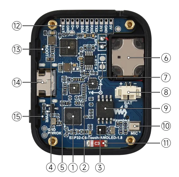
- ESP32-C6 Supports Wi-Fi and Bluetooth SoC, with a 160MHz operating frequency
- QMI8658 6-axis IMU includes a 3-axis gyroscope and a 3-axis accelerometer
- PCF85063 RTC chip
- AXP2101 Highly integrated power management IC
- ES8311 Low power audio codec IC
- Speaker Onboard speaker output
- Backup Batt pads Maintains RTC power supply during main battery replacement
- MX1.25 Lithium Batt header MX1.25 2PIN connector, for 3.7V Lithium Batt (optional), supports charging and discharging. (To fit inside the case, a Batt size of 3.85 × 24 × 28 mm is recommended)
- 16MB NOR-Flash For storing data
- Microphone For audio capture
- Onboard antenna Supports 2.4GHz Wi-Fi (802.11 b/g/n) and Bluetooth 5 (LE)
- Reserved GPIO pads (pitch 1.5mm) Adapting available I/O function pins for easy expansion
- BOOT button For device startup and function debugging
- USB Type-C port ESP32-C6 USB interface, for program flashing and log printing
- PWM button For system power supply ON/OFF, supports custom functions
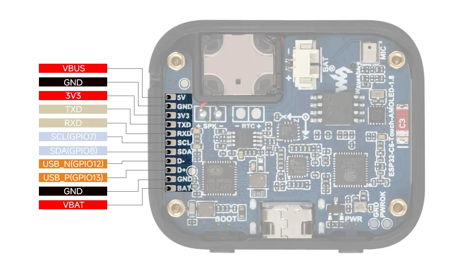
Pinout Definition
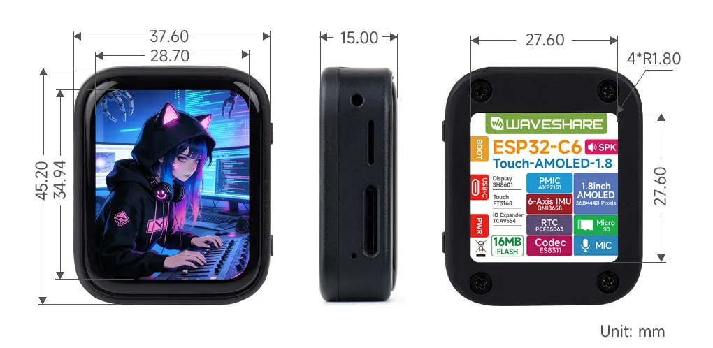
Dimensions
Development Methods
The ESP32-C6-Touch-AMOLED-1.8 supports two development frameworks: Arduino IDE and ESP-IDF, providing flexibility for developers to choose the tool that best fits their project requirements and personal preference.
Each method has its advantages, and developers can select based on their needs and skill level. Arduino is simple to learn and easy to get started with, suitable for beginners and non-professionals; ESP-IDF provides more advanced development tools and stronger control capabilities, suitable for developers with professional backgrounds or those with higher performance requirements, and is more suitable for complex project development.
Arduino IDE is a convenient, flexible, and easy-to-use open-source electronics prototyping platform. It requires minimal foundational knowledge, allowing for rapid development after a short learning period. Arduino has a vast global community that provides a wealth of open-source code, project examples, tutorials, and rich libraries that encapsulate complex functionalities, enabling developers to implement various features quickly. You can refer to the Working with Arduino to complete the initial setup, and the tutorial also provides related demos for reference.
ESP-IDF (Espressif IoT Development Framework) is a professional development framework released by Espressif for its ESP series chips. It is developed based on the C language, including a compiler, debugger, and flashing tool, etc. It supports development via command line or an Integrated Development Environment (such as Visual Studio Code with the Espressif IDF plugin), which provides features like code navigation, project management, and debugging, etc. We recommend using VS Code for development. For the specific configuration process, please refer to the Working with ESP-IDF. The tutorial also provides relevant demos for reference.
Working with Arduino
Note: This tutorial uses the ESP32-S3-Zero as a reference example, and all hardware code is based on its pinout. Before you start, we recommend checking the pinout of your development board to ensure the pin configuration is correct.
Setting Up Development Environment
1. Installing and Configuring Arduino IDE
Please refer to the tutorial Installing and Configuring Arduino IDE Tutorial to download and install the Arduino IDE and add ESP32 support.
2. Installing Libraries
- When installing Arduino libraries, there are typically two methods: Online Installation and Offline Installation. If the library installation requires offline installation, you must use the provided library file.
- For most libraries, users can easily search and install them through the online Library Manager in the Arduino software. However, some open-source libraries or custom libraries are not synchronized to the Arduino Library Manager, so they cannot be acquired through online searches. In this case, users can only manually install these libraries offline. You can click this link to download the demo package for the ESP32-C6-Touch-AMOLED-1.8 board from the
Arduinodirectory. TheArduino\librariesdirectory within the package already includes all the library files required for this tutorial.
Library/File Name Description Version Installation Method GFX Library for Arduino ST7789 display driver graphics library v1.6.4 Install via library manager or manually SensorLib PCF85063, QMI8658 sensor driver library v0.3.3 Install via library manager or manually XPowersLib AXP2101 driver library v0.2.6 Install via library manager or manually lvgl LVGL display framework v8.4.0 Install via library manager or manually Arduino_DriveBus I2C, touch driver library v1.0.1 Install manually Adafruit_BusIO Abstracted I2C/SPI communication v1.0.1 Install via library manager or manually Adafruit_XCA9554 I2C GPIO expander library v1.0.1 Install via library manager or manually Mylibrary Board pin macro definition —— Install manually ui_a Custom UI library —— Install manually ui_b Custom UI library —— Install manually ui_c Custom UI library —— Install manually lv_conf.h LVGL configuration file —— Install manually VERSION COMPATIBILITY DESCRIPTIONThere are strong dependencies between versions of LVGL and its driver libraries. For example, a driver written for LVGL v8 may not be compatible with LVGL v9. To ensure stable reproduction of the examples, it is recommended to use the specific versions listed in the table above. Mixing different library versions may cause compilation failures or runtime exceptions.
Installation Steps:
Download the demo package.
Copy all folders (Arduino_DriveBus, GFX_Library_for_Arduino, etc.) in the
Arduino\librariesdirectory to the Arduino library folder.INFOThe path to the Arduino libraries folder is typically:
c:\Users\<Username>\Documents\Arduino\libraries.You can also locate it within the Arduino IDE via File > Preferences, by checking the "Sketchbook location". The library folder is the
librariesfolder under this path.For other installation methods, please refer to: Arduino Library Management Tutorial.
Demo
The Arduino demos are located in the
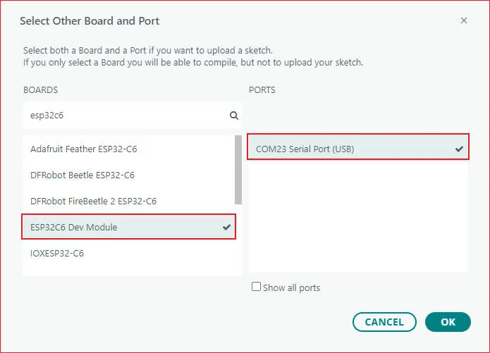
Arduino/examplesdirectory of the demo package.Demo Basic Program Description Dependency Library 01_HelloWorld Demonstrates the basic graphics library function and can also be used to test the basic performance of display screens and the display effect of random text GFX_Library_for_Arduino 02_Drawing_board Demonstrates the basic graphics library functions and can also be used to test the basic performance of display screens and the display effect of random text GFX_Library_for_Arduino, Arduino_DriveBus, Adafruit_XCA9554 03_GFX_AsciiTable Prints ASCII characters in rows and columns on the screen according to the screen size GFX_Library_for_Arduino 04_GFX_FT3168_Image Shows image display effects, switching displayed images via touch GFX_Library_for_Arduino, Arduino_DriveBus, Adafruit_XCA9554 05_GFX_PCF85063_simpleTime GFX library displays the current time SensorLib, GFX_Library_for_Arduino 06_GFX_ESPWiFiAnalyzer Draws WiFi band signal strength on the screen GFX_Library_for_Arduino 07_GFX_Clock Implements a clock using simple marker pointers and time management GFX_Library_for_Arduino 08_LVGL_Animation Custom UI to control backlight brightness LVGL, Arduino_DriveBus, ui_a 09_LVGL_change_background Custom UI to control background colorbrightness LVGL, Arduino_DriveBus, ui_b 10_LVGL_PCF85063_simpleTime LVGL library displays the current time LVGL, SensorLib 11_LVGL_QMI8658_ui LVGL draws an acceleration line chart LVGL, SensorLib 12_LVGL_Widgets LVGL demonstration LVGL, Arduino_DriveBus, Adafruit_XCA9554 13_ES8311 ES8311 driver example, plays simple audio —— 14_LVGL_Sqprj SquareLine UI combined with LVGL example LVGL - ESP32-C6-Touch-AMOLED-1.8 select model
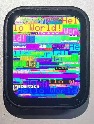
01_HelloWorld
Demo Description
- This demo demonstrates how to control the SH8601 display using the Arduino GFX library, demonstrating basic graphics library functions through dynamically changing text. This code can also be used to test the basic performance of the display and the random text display effects
Hardware Connection
- Connect the development board to the computer
Code Analysis
Display initialization:
if (!gfx->begin()) {
   USBSerial.println("gfx->begin() failed!");
}
Clear the screen and display text:
 gfx->fillScreen(BLACK);
 gfx->setCursor(10, 10);
 gfx->setTextColor(RED);
 gfx->println("Hello World!");
Animated display:
 gfx->setCursor(random(gfx->width()), random(gfx->height()));
 gfx->setTextColor(random(0xffff), random(0xffff));
 gfx->setTextSize(random(6), random(6), random(2));
 gfx->println("Hello World!");
Execution Result
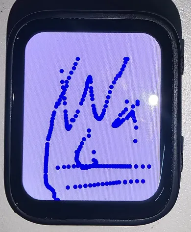
02_Drawing_board
Demo Description
- This example demonstrates how to use the ESP32 to control the FT3168 touch controller and TCA9554 GPIO expander via the I2C interface, while using the Arduino GFX and Arduino_DriveBus libraries to drive the SH8601 display
Hardware Connection
- Connect the development board to the computer
Code Analysis
Display initialization and brightness fade animation:
 gfx->begin();
 gfx->fillScreen(WHITE);
 for(int i = 0;i <= 255;i++){
    gfx->Display_Brightness(i);
    gfx->setCursor(30, 150);
    gfx->setTextColor(BLUE);
    gfx->setTextSize(4);
    gfx->println("Loading board");
    delay(3);
 }
Touch interrupt handling and coordinate reading:
 gfx->fillScreen(BLACK);
 gfx->setCursor(10, 10);
 gfx->setTextColor(RED);
 gfx->println("Hello World!");
Animated display:
 void Arduino_IIC_Touch_Interrupt(void) {
    FT3168->IIC_Interrupt_Flag = true;
 }

 int32_t touchX = FT3168->IIC_Read_Device_Value(FT3168->Arduino_IIC_Touch::Value_Information::TOUCH_COORDINATE_X);
 int32_t touchY = FT3168->IIC_Read_Device_Value(FT3168->Arduino_IIC_Touch::Value_Information::TOUCH_COORDINATE_Y);

 if (FT3168->IIC_Interrupt_Flag == true) {
    FT3168->IIC_Interrupt_Flag = false;
    USBSerial.printf("Touch X:%d Y:%d\n", touchX, touchY);
    if (touchX > 20 && touchY > 20) {
       gfx->fillCircle(touchX, touchY, 5, BLUE);
    }
 }
Execution Result
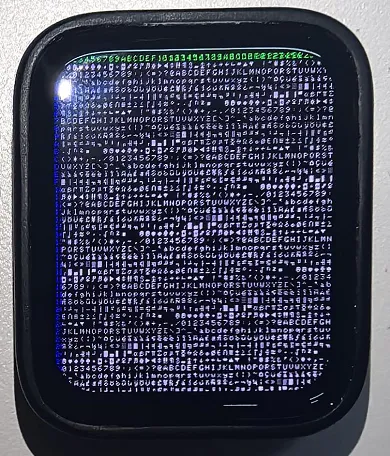
03_GFX_AsciiTable
Demo Description
- This demo shows how to display a basic ASCII character table on the SH8601 display by using the Arduino GFX library on an ESP32. The core function of the code is to initialize the display and print ASCII characters in rows and columns according to the screen size
Hardware Connection
- Connect the development board to the computer
Code Analysis
Create data bus and graphic display objects
- Here a data bus object
busis created for communicating with the display, initialized with specific pin configurations. Then a graphics display objectgfxis created, passing parameters such as the data bus, reset pin, rotation angle, whether it is an IPS panel, and the width and height of the display
 Arduino_DataBus *bus = new Arduino_ESP32QSPI(
    LCD_CS /* CS */, LCD_SCLK /* SCK */, LCD_SDIO0 /* SDIO0 */, LCD_SDIO1 /* SDIO1 */,
    LCD_SDIO2 /* SDIO2 */, LCD_SDIO3 /* SDIO3 */);

 Arduino_GFX *gfx = new Arduino_SH8601(bus, -1 /* RST */,
0 /* rotation */, false /* IPS */, LCD_WIDTH, LCD_HEIGHT);- Here a data bus object
Draw row and column numbers and character table
- First set the text color to green and print the row numbers one by one on the display. Then set the text color to blue and print the column numbers. Next, use a loop to draw each character individually, forming the character table, with each character using white foreground and black background
 gfx->setTextColor(GREEN);
 for (int x = 0; x < numRows; x++) {
    gfx->setCursor(10 + x * 8, 2);
    gfx->print(x, 16);
 }
 gfx->setTextColor(BLUE);
 for (int y = 0; y < numCols; y++) {
    gfx->setCursor(2, 12 + y * 10);
    gfx->print(y, 16);
 }

 char c = 0;
 for (int y = 0; y < numRows; y++) {
    for (int x = 0; x < numCols; x++) {
       gfx->drawChar(10 + x * 8, 12 + y * 10, c++, WHITE, BLACK);
    }
 }
Execution Result
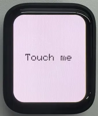
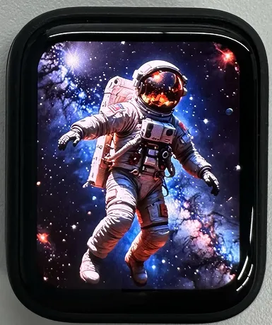
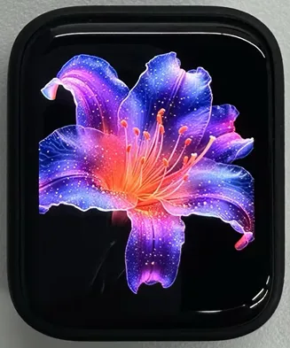
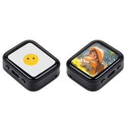
04_GFX_FT3168_Image
Demo Description
- This demo implements a touch screen display interface using the QSPI-driven SH8601 display on an ESP32-S3. It integrates an I2C touch controller (FT3168) for detecting touch input, as well as an I2C GPIO expander (TCA9554) for managing additional output pins. This code sets up the display screen, touch controller, and expander, and cycles through multiple images when the screen is touched
Hardware Connection
- Connect the development board to the computer
Code Analysis
- Image display:
 if (fingers_number > 0) {
    switch (Image_Flag) {
       case 0: gfx->draw16bitRGBBitmap(0, 0, (uint16_t *)gImage_1, LCD_WIDTH, LCD_HEIGHT); break;
       case 1: gfx->draw16bitRGBBitmap(0, 0, (uint16_t *)gImage_2, LCD_WIDTH, LCD_HEIGHT); break;
       case 2: gfx->draw16bitRGBBitmap(0, 0, (uint16_t *)gImage_3, LCD_WIDTH, LCD_HEIGHT); break;
       case 3: gfx->draw16bitRGBBitmap(0, 0, (uint16_t *)gImage_4, LCD_WIDTH, LCD_HEIGHT); break;
       case 4: gfx->draw16bitRGBBitmap(0, 0, (uint16_t *)gImage_5, LCD_WIDTH, LCD_HEIGHT); break;
    }
 Image_Flag++;
 if (Image_Flag > 4) {
       Image_Flag = 0;
    }
 }
Code Modification
- The image content resources are large. You need to set: Tools -> Partition Scheme -> 16M Flash (3MB APP/9.9MB FATFS)
Execution Result
05_GFX_PCF85063_simpleTime
Demo Description
- This demo demonstrates how to use the PCF85063 RTC module to display the current time on the SH8601 display. It retrieves the time every second and updates the display only when the time changes
Hardware Connection
- Connect the development board to the computer
Code Analysis
setup: Performs demo initialization settings
- Initializes the serial port to provide a channel for outputting error messages
- Initializes the real-time clock chip, including connection checks and setting the initial time to ensure time accuracy
- Initializes the graphics display device, sets the background color and brightness, providing a visual interface for time display
loop: Continuously checks for time changes and updates the time display on the screen during program execution
- Periodically checks if the time has changed by comparing the difference between the current time and the last updated time to determine if an update is needed
- Retrieves time information from the RTC and formats it for correct display on the screen
- If the time changes, clears the previous time display area, sets text color and size, calculates the centered position, and displays the new time on the screen. Finally saves the current time as the previous time for the next comparison
Execution Result

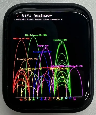
06_GFX_ESPWiFiAnalyzer
Demo Description
- This demo demonstrates drawing WiFi band signal strength on the SH8601 display, implementing the function of a WiFi analyzer
Hardware Connection
- Connect the development board to the computer
Code Analysis
setup: Prepares for the initialization of the entire program
- Initializes serial port communication, sets the baud rate to 115200 for outputting information and debugging
- Sets WiFi to station mode and disconnects, preparing for subsequent network scanning
- Performs some additional pre-initialization operations based on different hardware conditions (if GFX_EXTRA_PRE_INIT is defined)
- Initializes the graphic display device, calculates some display-related parameters such as text size, banner height, etc., and sets the display brightness. Finally draws the initial banner information
loop: Executes the main program logic, including performing WiFi network scanning, processing scan results, drawing charts and displaying statistical information, and performing power-saving operations as needed
- WiFi scanning and processing: Performs WiFi network scanning, obtains the number of networks and various network information; counts the number of access points per channel, calculates noise levels and determines signal peaks; draws WiFi signal strength charts based on scan results, including drawing ellipses representing signal strength and displaying related network information
- Displaying statistical information: Prints the number of networks found and information about channels with less noise on the display, draws chart baselines and channel markers, and displays the number of access points per channel
- Power-saving operations: Based on the configured number of scans, performs power-saving operations when conditions are met, such as turning off the display power pin and entering deep sleep mode
Execution Result
07_GFX_Clock
Demo Description
- This demo demonstrates a simple SH8601 clock, implementing a clock example using simple marker pointers and time management
Hardware Connection
- Connect the development board to the computer
Code Analysis
- Drawing hour, minute, and second hands:
 void redraw_hands_cached_draw_and_erase() {
    gfx->startWrite();
    draw_and_erase_cached_line(center, center, nsx, nsy, SECOND_COLOR, cached_points, sHandLen + 1, false, false);
    draw_and_erase_cached_line(center, center, nhx, nhy, HOUR_COLOR, cached_points + ((sHandLen + 1) * 2), hHandLen + 1, true, false);
    draw_and_erase_cached_line(center, center, nmx, nmy, MINUTE_COLOR, cached_points + ((sHandLen + 1 + hHandLen + 1) * 2), mHandLen + 1, true, true);
    gfx->endWrite();
 }
Execution Result

08_LVGL_Animation
Demo Description
- This demo demonstrates a simple LVGL slider example that can change the screen backlight brightness by adjusting the slider value
Hardware Connection
- Connect the development board to the computer
Code Analysis
- Modify the backlight brightness in real time
 int32_t slider_value = lv_slider_get_value(ui_Slider1);
 int32_t brightness = map(slider_value, 0, 100, 5, 255);
 gfx->Display_Brightness(brightness);
Execution Result

09_LVGL_change_background
Demo Description
- This demo demonstrates an LVGL background brightness/darkness scene change, implementing background color changes by defining simple button components
Hardware Connection
- Connect the development board to the computer
Code Analysis
- setup: Responsible for the initialization of the entire system
- First, initializes the serial port for possible debugging output
- Then initializes the I2C bus and expansion chip, setting the pin modes and initial states of the expansion chip
- Continuously attempts to initialize the touch controller, setting its power mode upon success
- Initializes the graphics display device and sets brightness, also prints LVGL and Arduino version information
- Initializes LVGL, including registering a debug print callback function, initializing display driver and input device driver
- Creates and starts an LVGL timer, initializes the user interface and prints the setup completion message
- loop
- In the main loop, continuously calls lv_timer_handler() to let the LVGL graphics library handle various tasks
- Adds a small delay to avoid excessive CPU resource consumption
- my_touchpad_read: Reads the coordinates of the touchpad, sets the state of LVGL's input device based on touch status, and updates touch coordinates
Execution Result


10_LVGL_PCF85063_simpleTime
Demo Description
- This demo demonstrates using the PCF85063 RTC module to display the current time on the SH8601 display under LVGL. It retrieves the time every second and updates the display only when the time changes, resulting in better time refresh effects
Hardware Connection
- Connect the development board to the computer
Code Analysis
- setup: Responsible for initializing various hardware devices and the LVGL graphics library environment
- Serial initialization: USBSerial.begin(115200) prepares for serial debugging
- Real-time clock initialization: Attempts to initialize the real-time clock rtc. If it fails, enters an infinite loop. Set the date and time
- Touch controller initialization: Continuously attempts to initialize the touch controller FT3168. If initialization fails, prints an error message and waits with a delay; prints a success message upon success
- Graphics display initialization: Initializes the graphics display device gfx, sets brightness, and prints LVGL and Arduino version information Then initializes the LVGL, including registering a print callback function for debugging, initializing the display driver and the input device driver. Creates and starts an LVGL timer. Finally creates a label and sets its initial text to "Initializing..."
- loop
- lv_timer_handler(): This is an important function in the LVGL graphics library, used to handle various timer events, animation updates, input processing, and other tasks for the graphical interface. Calling this function in each loop ensures the graphical interface runs smoothly and responds to interactions promptly
- Time update and display: Gets the real-time clock time every second and prints it via the serial port. Then formats the time into a string and updates the text of the label to display the current time. Simultaneously sets the font of the label to a specific font. Finally adds a small delay
Execution Result

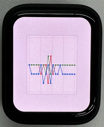
11_LVGL_QMI8658_ui
Demo Description
- This demo demonstrates using LVGL for graphical display, communicating with the QMI8658 IMU to obtain accelerometer and gyroscope data
Hardware Connection
- Connect the development board to the computer
Code Analysis
- setup: Responsible for initializing various hardware devices and the LVGL graphics library environment
- Serial initialization: USBSerial.begin(115200) prepares for serial debugging
- Touch controller initialization: Continuously attempts to initialize the touch controller FT3168. If initialization fails, prints an error message and waits with a delay; prints a success message upon success
- Graphics display initialization: Initializes the graphics display device gfx, sets brightness, and prints LVGL and Arduino version information Then initializes the LVGL, including registering a print callback function for debugging, initializing the display driver and the input device driver. Creates and starts an LVGL timer. Finally creates a label and sets its initial text to "Initializing..."
- Creating a chart: Creates a chart object chart, sets chart properties such as type, range, number of data points, etc., and adds data series for the three axes of acceleration
- Acceleration sensor initialization: Initializes the acceleration sensor qmi, configures accelerometer and gyroscope parameters, enables them, and prints the chip ID and control register information
- loop
- lv_timer_handler(): This is an important function in the LVGL graphics library, used to handle various timer events, animation updates, input processing, and other tasks for the graphical interface. Calling this function in each loop ensures the graphical interface runs smoothly and responds to interactions promptly
- Reading acceleration sensor data: If acceleration sensor data is ready, reads acceleration data and prints it via the serial port, while updating the chart to display acceleration data. If the gyroscope data is ready, reads the gyroscope data and prints it via the serial port. Finally adds a small delay to increase data polling frequency
Execution Result
12_LVGL_Widgets
Demo Description
- This example demonstrates LVGL Widgets. The frame rate can reach 50~60 fps in dynamic states. Optimizing the SH8601 display library can achieve smoother frame rates. This can be compared with scenarios where double buffering and dual acceleration are enabled in the ESP-IDF environment
Hardware Connection
- Connect the development board to the computer
Code Analysis
- setup: Responsible for initializing various hardware devices and the LVGL graphics library environment
- Serial initialization: USBSerial.begin(115200) prepares for serial debugging
- I2C bus Initialization: Wire.begin(IIC_SDA, IIC_SCL); initializes I2C bus for communicating with other I2C devices
- Expansion chip initialization: Creates and initializes the expansion chip expander, sets pin modes to output, and performs some initial pin state settings
- Touch controller initialization: Continuously attempts to initialize the touch controller FT3168. If initialization fails, prints an error message and waits with a delay; prints a success message upon success
- Graphics display initialization: Initializes the graphics display device gfx, sets brightness, and obtains the width and height of the screen. Then initializes LVGL, including registering a print callback function for debugging, setting the touch controller's power mode to monitoring mode, initializing display driver and input device driver. Creates and starts an LVGL timer. Creates a label and sets its text. Finally calls lv_demo_widgets() to showcase LVGL example widgets
- loop
- lv_timer_handler(): This is an important function in the LVGL graphics library, used to handle various timer events, animation updates, input processing, and other tasks for the graphical interface. Calling this function in each loop ensures the graphical interface runs smoothly and responds to interactions promptly
- delay(5);: Adds a small delay to avoid excessive CPU resource consumption
Execution Result
13_ES8311
Demo Description
- This demo demonstrates using I2S to drive the ES8311 chip, playing the converted binary audio file
Hardware Connection
- Connect the development board to the computer
Code Analysis
- es8311_codec_init: Initializes the ES8311 audio codec.
- Creates an ES8311 codec handle es_handle
- Configures ES8311 clock parameters, including master clock and sampling clock frequencies, clock polarity, etc.
- Initializes the codec, sets audio resolution to 16-bit
- Configures sampling frequency
- Configures microphone-related parameters, such as turning off the microphone, setting volume and microphone gain
- setup: Performs overall initialization settings, including serial port, pins, I2S, and the ES8311 codec
- Initializesserial port for debugging output
- Sets a specific pin as output and pulls it high
- Configures the I2S bus, setting pins, operating mode, sample rate, data bit width, channel mode, etc.
- Initializes the I2C bus
- Calls the es8311_codec_init function to initialize the ES8311 codec
- Plays a pre-defined audio data (canon_pcm) via the I2S bus
Execution Result
- The device will play auido directly without showing content on the screen
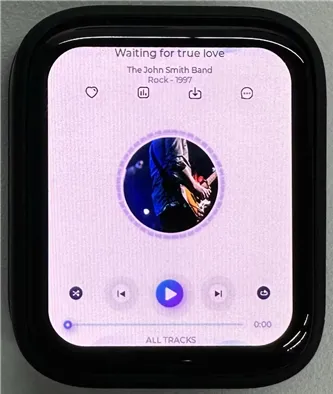
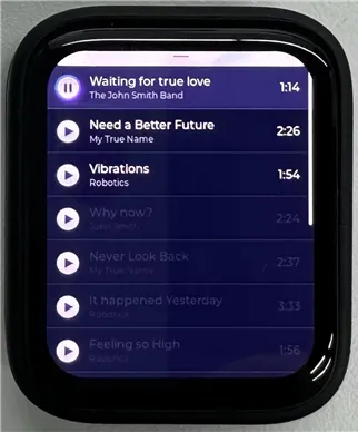
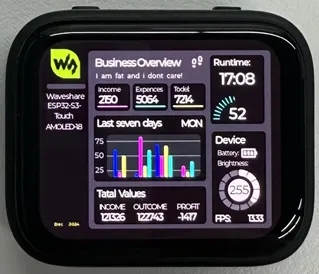
14_LVGL_Sqprj
Demo Description
- This demo demonstrates SquareLine UI combined with LVGL. It uses the QMI8658 sensor to achieve adaptive screen display orientation, displays real-time time via WiFi, and changes backlight brightness by detecting touch input in specific areas
Hardware Connection
- Connect the development board to the computer
Code Analysis
- setup
- Serial initialization
- Wi-Fi initialization: Wi-Fi connection and network time configuration
- I2C communication and expander initialization: Initializes I2C communication bus, specifies SDA and SCL pins, configures multiple pins (pins 0, 1, 2, 6) of the expander
- Sensor initialization: Initializes the QMI8658 sensor, initializes the touch controller (FT3168 object)
- Display initialization and related configuration
- loop()
- Interface rotation processing based on sensor data
- LVGL graphical interface update
- Display brightness adjustment processing
- Interface element value updates
Execution Result
- The image content resources are large. You need to set: Tools -> Partition Scheme -> 16M Flash (3MB APP/9.9MB FATFS)
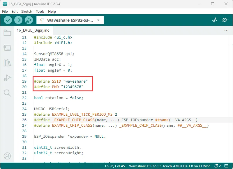
- Modify to your available WiFi
Execution Result
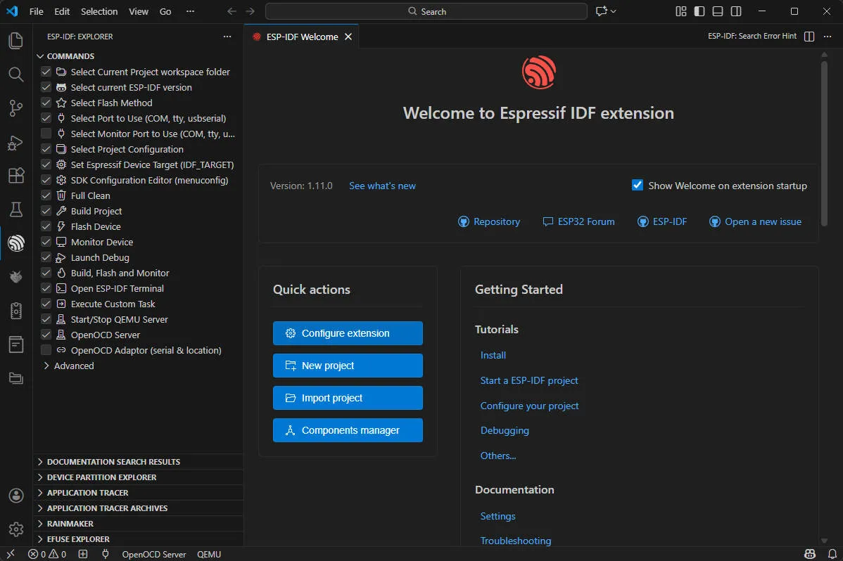
Working with ESP-IDF
This chapter includes the following sections, please read as needed:
Setting Up Development Environment
NOTEThe following environment settings are applicable to Windows 10/11 systems. For Mac/Linux users, please refer to the official instructions
Download and install Visual Studio Code.
In VS Code, open the Extensions view by clicking the
 in the VS Code sidebar or using the shortcut (Ctrl+Shift+X). Then, search for the ESP-IDF extension and install it.
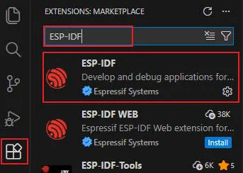
After the extension is installed, the
 will appear in the activity bar on the left side of VS Code. Clicking this icon will view the basic command list for the ESP-IDF extension. Select Configure ESP-IDF extension under Advanced.
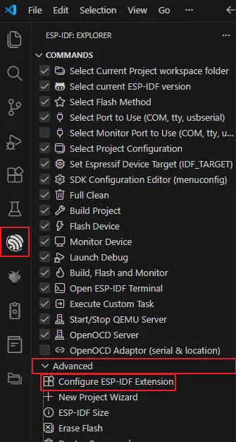
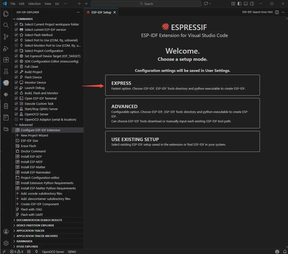
Choose Express to enter quick configuration mode:
Modify the following options as needed:
- Select download server:
- Espressif: For users in China, use Espressif's China server for faster downloads.
- Github: Use the official GitHub release link.
- ESP-IDF Version: Typically, select the version required by the development board. If no specific requirement, it's recommended to use the latest stable version. For ESP32-C6-Touch-AMOLED-1.8, it is recommended to use the Espressif IDF version ≥ v5.5.0.
- ESP-IDF Container directory: It is recommended to use the default path, or use a path that contains only English characters and no spaces.
- ESP-IDF Required Tools directory: It is recommended to use the default path, or use a path that contains only English characters and no spaces.
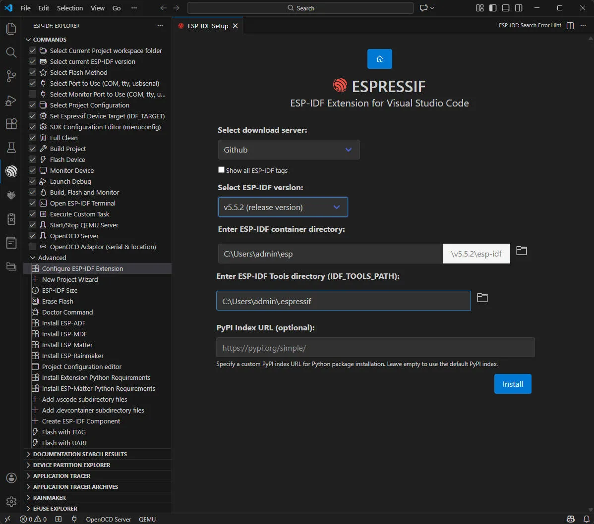
- Select download server:
Click Install to start the installation. You will see a page displaying the installation progress, including the progress status of ESP-IDF download, ESP-IDF tool download and installation, as well as the creation of the Python virtual environment.

If everything is installed correctly, you'll get a prompt confirming all the setup is done, and you're ready to start using the extension.
WARNINGNote: If ESP-IDF installation fails or needs to be reinstalled, you can try deleting the
C:\Users\%Username%\espandC:\Users\%Username%\.espressiffolders and then retry.Demo
The ESP-IDF demos are located in the
ESP-IDFdirectory of the demo package.Demo Basic Description 01_AXP2101 Drives the AXP2101 PMU using the ported XPowersLib to get power-related data 02_PCF85063 Drives the PCF85063 RTC for time storage and reading 03_esp_brookesia Show a complete mobile-style UI system, including components such as the status bar, navigation bar, app launcher, and gesture interactions 04_QMI8658 Drives the QMI8658 IMU using the ported SensorLib to get gyroscope-related data 05_LVGL_WITH_RAM Run the LVGL demo by enabling double buffering and DMA acceleration to prevent tearing 01_AXP2101
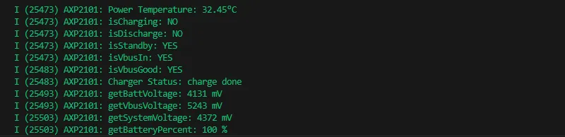
Demo Description
- This demo demonstrates porting XPowersLib in ESP-IDF, and driving AXP2101 to obtain power-related data through the ported XPowersLib
Hardware Connection
- Connect the development board to the computer
Code Analysis
- i2c_init: Initializes the I2C master to prepare for communication with other devices (like the PMU)
- Configures I2C parameters, including setting the master device mode, specifying the SDA and SCL pins, enabling the pull-up resistor, and determining the clock frequency
- Installs the I2C driver and apply the configuration to the actual hardware
- pmu_register_read: Reads a series of bytes of data from a specific register on the PMU
- Performs parameter checks to ensure the incoming parameters are valid and avoid invalid read operations
- Performs I2C operations in two steps, first sends the register address to read, then reads the data. During the reading process, different processing is carried out according to the length of bytes to be read to ensure accurate reading of the data. At the same time, handles error cases in the I2C communication process and returns the corresponding status code so that the upper-layer code can determine if the read operation is successful
Expected Result
- This demo will not light up the screen
- The serial port monitor displays the parameters: chip temperature, charging state, discharging state, standby state, Vbus connection, Vbus condition, charger status, battery voltage, Vbus voltage, system voltage, battery percentage
02_PCF85063
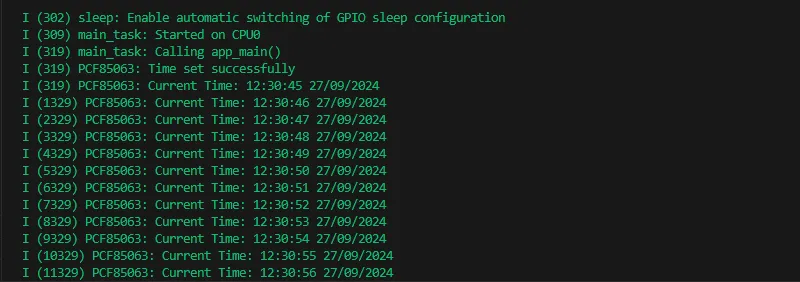
Demo Description
- This demo uses a simple way to drive the PCF85063 for time storage and reading functionality
Hardware Connection
- Connect the development board to the computer
Code Analysis
- i2c_master_init
- Defines the I2C configuration structure conf, set the master device mode, SDA and SCL pins, pull-up resistor, and clock frequency
- Uses the i2c_param_config function to configure I2C parameters. If the configuration fails, an error log is recorded and an error code is returned
- Uses the i2c_driver_install function to install the I2C driver, apply the configuration to the actual hardware, and return the result
- rtc_get_time
- Defines a 7-byte array to store the read time data
- Calls the rtc_read_reg function to read 7 bytes of time data starting from the specific register address (0x04) of the RTC chip. If the reading fails, an error log is recorded and an error code is returned
- Processes the time data read, separately extract the seconds, minutes, hours, days, weeks, months, and years, and convert BCD to decimal
- Uses ESP_LOGI to output the formatted current time
Expected Result
- This demo will not light up the screen
- The serial port monitor prints time information
03_esp_brookesia
Demo Description
- This example showcases a complete mobile-style UI system. It includes components like a status bar, navigation bar, app launcher, and gesture interactions.
Hardware Connection
- Connect the development board to the computer
Expected Result


04_QMI8658
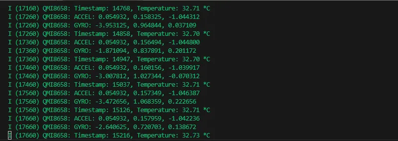
Demo Description
- This demo demonstrates porting SensorLib in ESP-IDF, then using the ported SensorLib to drive qmi8658 to obtain gyroscope-related data
Hardware Connection
- Connect the development board to the computer
Code Analysis
- setup_sensor: Sets up and initializes the environment and parameters required to communicate with the QMI8658 sensor
- Initializes I2C communication to ensure that the connection channel to the sensor is established
- Initializes the sensor, check if the sensor is properly connected
- Configures the sensor's accelerometer and gyroscope parameters to meet specific application needs
- Enables the sensor to start collecting data
- read_sensor_data: Reads and processes data from the QMI8658 sensor in a continuous loop and outputs the results
- In the loop, continuously checks if the sensor data is ready
- When the data is ready, the accelerometer, gyroscope, timestamp, and temperature data are read and logged out
- Handles the failure of data reading by recording an error log for troubleshooting
- Controls the execution speed of the loop through delay to avoid excessive consumption of system resources
Expected Result
- This demo will not light up the screen
- The serial port monitor prints sensor data
05_LVGL_WITH_RAM
Demo Description
- This example shows LVGL demo, which can run LVGL demo by enabling dual caching, enabling DMA acceleration and anti-tearing, etc. to run dynamic graphics and texts smoothly, achieving a frame rate of 200-300 FPS
Hardware Connection
- Connect the development board to the computer
Code Analysis
- app_main: The initialization and startup process of the entire application
- Hardware initialization: Configures and initializes hardware devices related to LCD display and touch input (if available), such as GPIO pins, SPI bus, I2C bus, LCD panel driver, and touch controller driver, etc.
- LVGL initialization: Initializes the LVGL library, allocates drawing buffers, registers display driver and touch input device driver (if available), installs timers, and creates smutexes and starts LVGL tasks
- Example display: Finally shows LVGL examples, such as widget examples, etc.
- example_lvgl_port_task: LVGL task function, responsible for handling LVGL regular updates and task delay control, ensuring the smooth operation of the LVGL interface
- Timed update: In its loop, it grabs a mutex lock and calls the lv_timer_handler to handle the LVGL timer event, which updates the UI state
- Delay control: Determine the task's delay time based on the results of timer processing to avoid excessive CPU resource usage and ensure timely response to LVGL events
Expected Result


Resources
1. Hardware Resources
Development Board Design File
- Schematic: ESP32-C6-Touch-AMOLED-1.8-Schematic
2. Technical Manuals
Official ESP32-C6 Chip Manuals
- Datasheets:
- Technical Manuals:
Onboard Component Datasheets
3. Demo
- GitHub Example Program Repository: ESP32-C6-Touch-AMOLED-1.8_Demo
Support
Monday-Friday (9:30-6:30) Saturday (9:30-5:30)
Email: services01@spotpear.com
[Tutorial Navigation]
- ESP32-C6-Touch-AMOLED-1.8
- Working with Arduino
- Setting Up Development Environment
- Demo
- Working with ESP-IDF
- Setting Up Development Environment
- Demo
- Resources
- Support