- sales/support
Google Chat:---
- sales
+86-0755-88291180
- sales01
sales@spotpear.com
- sales02
dragon_manager@163.com
- support
tech-support@spotpear.com
- CEO-Complaints
zhoujie@spotpear.com
- Only Tech-Support
WhatsApp:13246739196
- Purchase/Shipping/Refund
WhatsApp:13424403025
- HOME
- >
- ARTICLES
- >
- Common Moudle
- >
- ESP
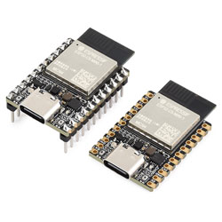
ESP32-C5-MINI-KIT User Guide
Features
- Utilizes the ESP32-C5-MINI-1 series module, equipped with a RISC-V 32-bit processor running at up to 240MHz.
- Integrated with 384KB SRAM, 320KB ROM, and 4MB Flash
- Integrates dual-band 2.4GHz & 5GHz Wi-Fi, Bluetooth 5 (LE), and IEEE 802.15.4 (supporting Zigbee 3.0 and Thread) wireless communication, delivering excellent RF performance.
- Features a reversible USB Type-C connector.
- Exposes rich peripheral interfaces with a castellated module design, facilitating soldering and integration onto user-designed carrier boards.
- Supports various low-power operating states, allowing flexible adjustment between communication range, data rate, and power consumption to meet the power requirements of various application scenarios.
Resource Interface
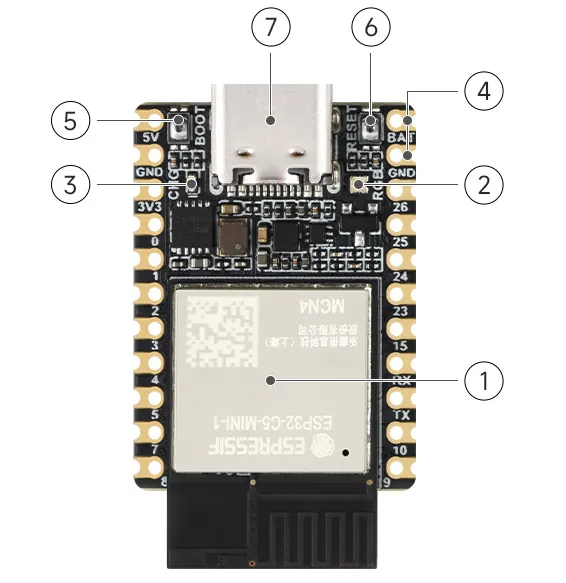
- ESP32-C5-MINI-1 module
- RGB indicator
- Charging indicator
- BAT pins for connecting battery positive, GND for battery negative
- BOOT button Press while resetting to enter download mode
- RESET button Reset button
- USB Type-C port For program downloading and serial debugging
Dimensions
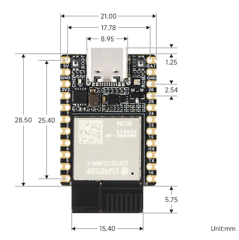
Pinout Definition
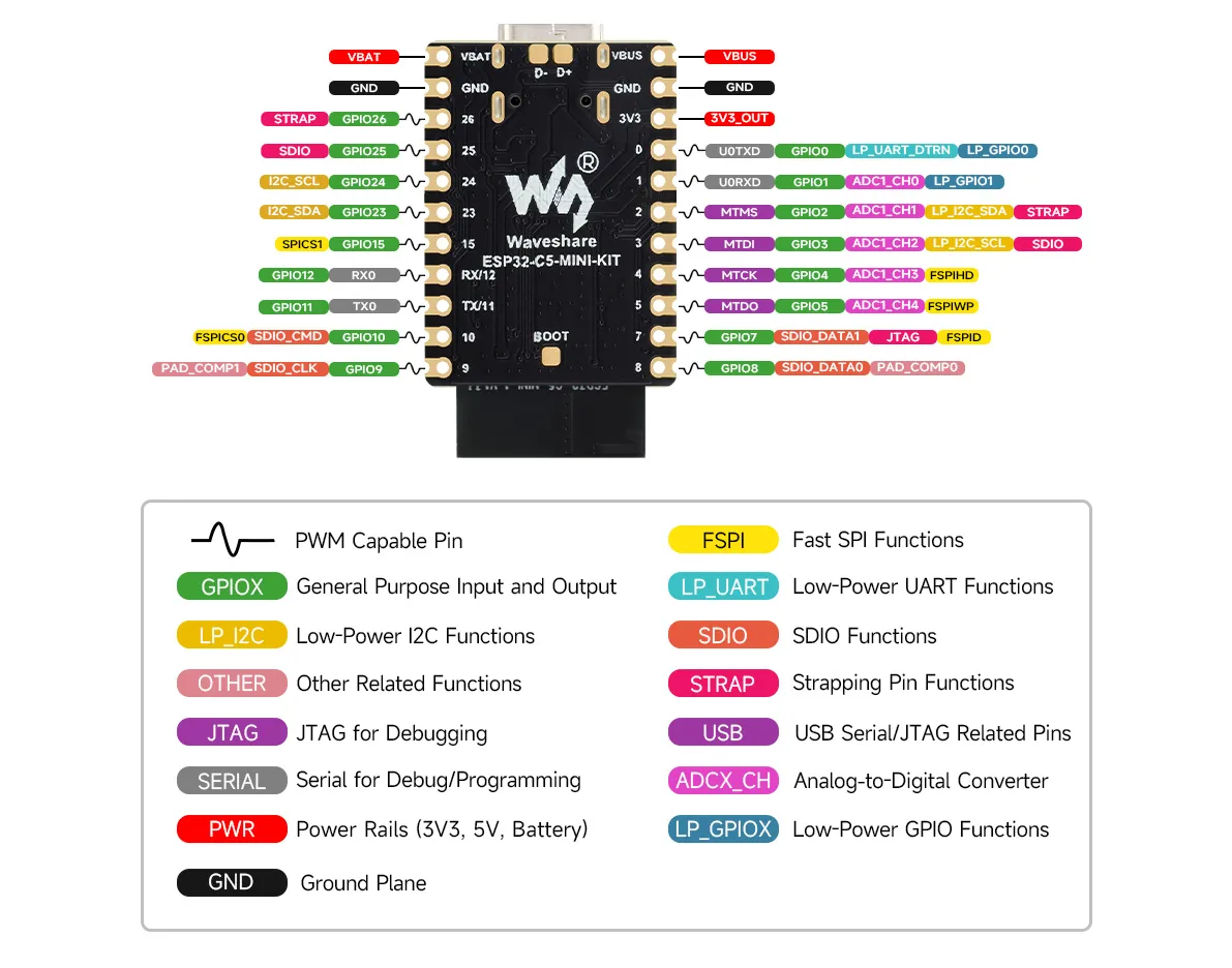
Working with Arduino
This chapter introduces the Arduino development environment for the ESP32-C5-MINI-KIT and the example programs provided in examples/Arduino/examples.
Setting Up the Development Environment
1. Install Arduino IDE and ESP32 Board Support Package
Please refer to the tutorial Install and Configure Arduino IDE to download and install the Arduino IDE and add ESP32 support.
After installing Arduino IDE, add the Espressif Arduino-ESP32 board index in "Preferences -> Additional Boards Manager URLs", and install the Arduino-ESP32 version that supports ESP32-C5 via the "Boards Manager". After installation, select ESP32C5 Dev Module in "Tools -> Board".
Connect the board via USB and select the corresponding serial port in "Tools -> Port". Unless otherwise noted, all examples in this directory use the serial monitor with baud rate set to 115200.
Arduino support for ESP32-C5 depends on the board package version. If the ESP32-C5 board option is not available in the IDE, please upgrade the Espressif Arduino-ESP32 board package first before compiling the examples.
2. Open an Example
Each example directory contains a .ino main file with the same name as the directory. Open that .ino file with the Arduino IDE to compile and upload.
Installing the Libraries
00_Board_Info, 01_WS2812_RGB, 02_WiFi_DualBand, and 03_UART_Loopback only depend on the components provided by the Arduino-ESP32 board package.
04_1.83inch_Touch_LCD_LVGL_GFX requires the following graphics libraries. This project already provides matching versions in examples/Arduino/libraries; it is recommended to use the libraries from this directory to avoid API version mismatches.
| Library | Version | Purpose | Installation Method |
|---|---|---|---|
lvgl | 8.4.0 | Graphics UI and touch input | Copy libraries/lvgl to the Arduino libraries folder |
GFX Library for Arduino | 1.6.5 | ST7789 display driver | Copy libraries/GFX_Library_for_Arduino to the Arduino libraries folder |
You can install the library packages via "Sketch -> Include Library -> Add .ZIP Library" in the Arduino IDE, or copy the two directories above to the libraries folder under your Arduino Sketchbook and restart the IDE.
The touchscreen example is written based on LVGL 8.4.0 display and input device APIs and cannot be directly switched to LVGL 9. Please use LVGL 8.4.0 and Arduino_GFX 1.6.5 from the project simultaneously.
Example
The example programs are located in this directory. Examples with external interfaces require connecting the corresponding devices or buses before running.
| Example | Description |
|---|---|
| 00_Board_Info | Prints ESP32-C5 chip, Flash, program, and memory information via serial. |
| 01_WS2812_RGB | Controls the onboard WS2812 RGB LED to cycle through red, green, blue, white, and off. |
| 02_WiFi_DualBand | Scans Wi-Fi networks, displays channel and band, and can connect to a specified network. |
| 03_UART_Loopback | Uses UART1 to send and receive data for a serial loopback test. |
| 04_1.83inch_Touch_LCD_LVGL_GFX | Drives the onboard 1.83inch touchscreen, performs color self-test, and touch drawing. |
00_Board_Info
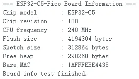
The program prints chip model, chip revision, CPU frequency, Flash size, compiled program size, remaining heap memory, and base MAC address after startup, then stays running. This example requires no extra hardware and is the preferred first test for verifying board connection, upload, and serial configuration.
01_WS2812_RGB
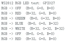
The onboard WS2812 RGB LED data pin is GPIO27. The program uses the Arduino-ESP32 rgbLedWriteOrdered() interface, sets brightness to 32, and toggles between red, green, blue, white, and off every second; the serial port simultaneously outputs the current RGB value.
This example does not rely on third-party libraries. If the LED color does not match expectations, check whether COLOR_ORDER needs to match the actual color order of the LED.
02_WiFi_DualBand
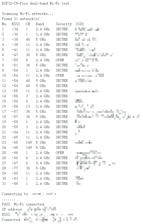
This example configures the chip in STA mode, scans available networks, and lists RSSI, channel, security status, and band via serial: channels 1 to 14 are marked as 2.4 GHz, others as 5 GHz.
To test network connectivity, first modify the configuration at the top of the source code:
static const char *WIFI_SSID = "MySSID";
static const char *WIFI_PASSWORD = "MyPassWord";
After uploading, the program waits up to 20 seconds to connect to the specified Wi-Fi and prints the IP address, RSSI, channel, and band; if the connection drops, it rescans networks.
03_UART_Loopback
This example uses UART1 for a self-loopback test with the following initialization:
| Signal | GPIO | Parameters |
|---|---|---|
| UART1 TX | GPIO0 | 115200, 8N1 |
| UART1 RX | GPIO1 | 115200, 8N1 |
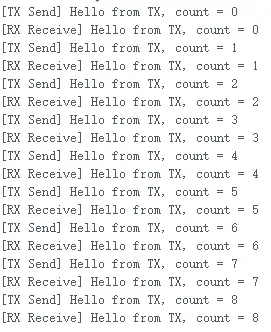
Connect GPIO0 to GPIO1 with a wire and upload the program. The program sends an incrementing count message via TX every two seconds, and prints [RX Receive] when it receives the same message on RX.
04_1.83inch_Touch_LCD_LVGL_GFX
This example uses Arduino_GFX to drive a 240 x 284 1.83inch Touch LCD and uses LVGL 8.4.0 to set up the display and touch input device. The touch controller is CST816 and the display controller is ST7789.
| Function | Signal | GPIO / Address |
|---|---|---|
| LCD software SPI | SCLK / MOSI / CS / DC / RST / BL | 7 / 8 / 9 / 10 / 15 / 25 |
| Touch I2C | SDA / SCL | GPIO23 / GPIO24 |
| Touch control | RST / INT | GPIO26 / GPIO5 |
| CST816 address | I2C | 0x15 |
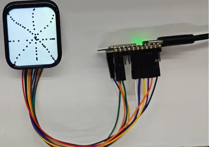
On startup, the program blinks the backlight, scans the I2C bus, displays five solid colors (red, yellow, blue, green, white) in sequence, and then initializes LVGL. After entering the main screen, you can draw black dots on a white canvas via touch. Before compiling, install LVGL and Arduino_GFX according to the versions listed in Installing the Libraries.
Working with ESP-IDF
This chapter includes the following sections, please read as needed:
ESP-IDF Getting Started
New to ESP32 ESP-IDF development and looking to get started quickly? We have prepared a general Getting Started Tutorial for you.
- Section 1: Environment Setup
- Section 2: Running Examples
- Section 3: Creating a Project
- Section 4: Using Components
- Section 5: Debugging
- Section 6: FreeRTOS
- Section 7: Peripherals
- Section 8: Wi-Fi Programming
- Section 9: BLE Programming
Please Note: This tutorial uses the ESP32-S3-Zero as a teaching example, and all hardware code is based on its pinout. Before you start, it is recommended that you check the pinout of your development board to ensure the pin configuration is correct.
Setting Up the Development Environment
The following guide uses Windows as an example, demonstrating development using VS Code + the ESP-IDF extension. macOS and Linux users should refer to the official documentation.
The screenshots in this section use ESP-IDF V5.5.2 as an example. When installing, please select the ESP-IDF version that matches your board's example.
Install the ESP-IDF Development Environment
Download the installation manager from the ESP-IDF Installation Manager page. This is Espressif's latest cross-platform installer. The following steps demonstrate how to use its offline installation feature.
Click the Offline Installer tab on the page, then select Windows as the operating system and the ESP-IDF version you need (the version shown in the screenshot is for reference only — choose the version that fits your actual needs).
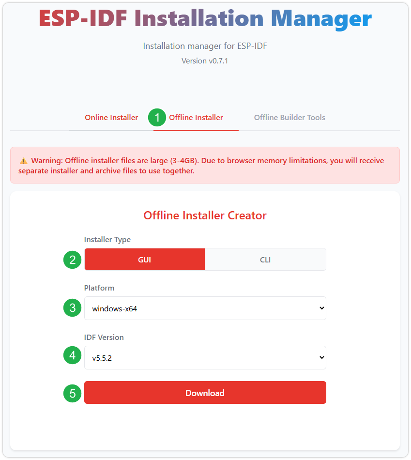
After confirming your selection, click the download button. The browser will automatically download two files: the ESP-IDF Offline Package (.zst) and the ESP-IDF Installer (.exe).
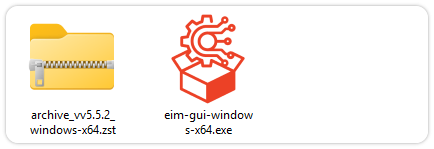
Please wait for both files to finish downloading.
Once the download is complete, double-click to run the ESP-IDF Installer (eim-gui-windows-x64.exe).
The installer will automatically detect if the offline package exists in the same directory. Click Install from archive.
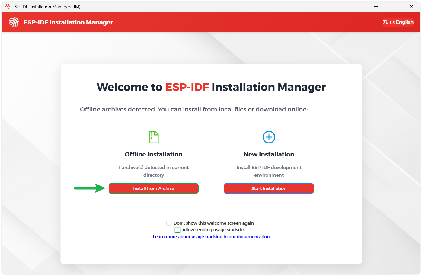
Next, select the installation path. We recommend using the default path. If you need to customize it, ensure the path does not contain Chinese characters or spaces. Click Start installation to proceed.
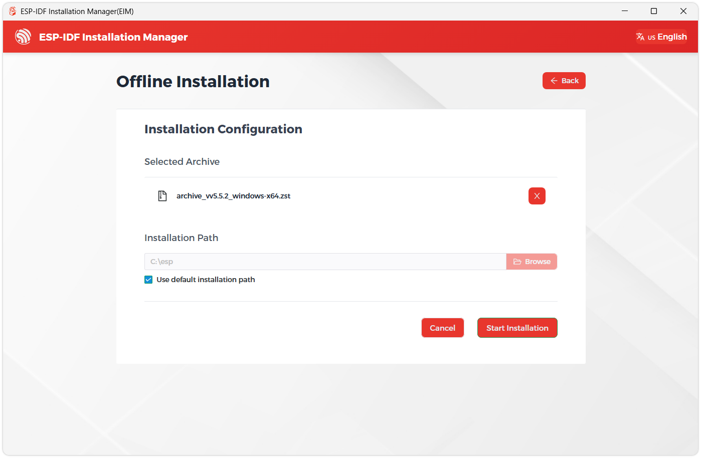
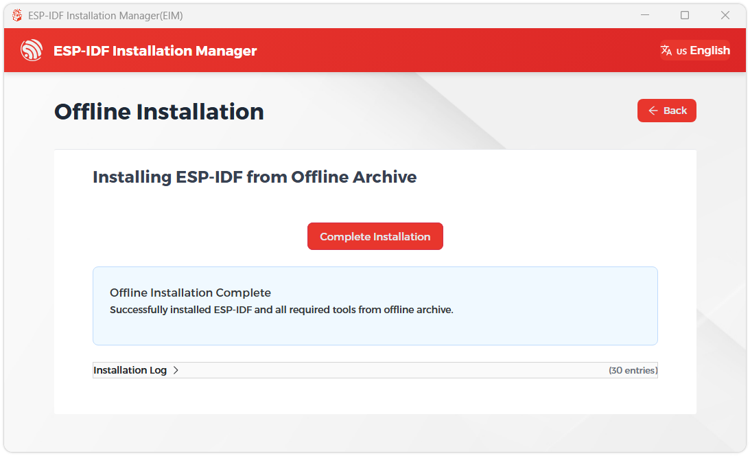
When you see the following screen, the ESP-IDF installation is successful.
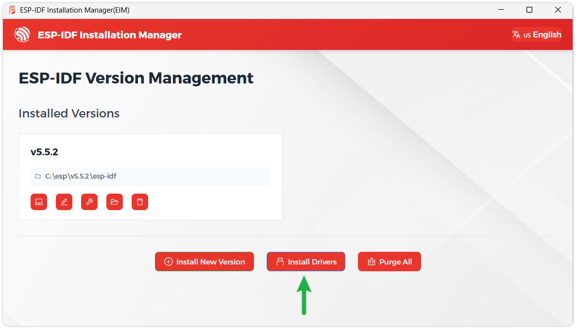
We recommend installing the drivers as well. Click Finish installation, then select Install driver.
Install Visual Studio Code and the ESP-IDF Extension
Download and install Visual Studio Code.
During installation, it is recommended to check Add "Open with Code" action to Windows Explorer file context menu to facilitate opening project folders quickly.
In VS Code, click the Extensions icon
 in the Activity Bar on the side (or use the shortcut Ctrl + Shift + X) to open the Extensions view.
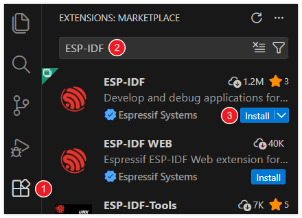
Enter ESP-IDF in the search box, locate the ESP-IDF extension, and click Install.
For ESP-IDF extension versions ≥ 2.0, the extension will automatically detect and recognize the ESP-IDF environment installed in the previous steps, requiring no manual configuration.
Example
This directory contains ESP-IDF example projects for the ESP32-C5-MINI-KIT. The projects are currently configured for the target chip esp32c5 with 4 MB of Flash.
Preparation Before Use
- Install and initialize ESP-IDF with ESP32-C5 support. ESP-IDF 6.0.2 is recommended.
- Open any example directory in a terminal where ESP-IDF has been initialized.
- Connect the board to your computer via USB, and identify its serial port name (e.g.,
COM5under Windows).
Each example is an independent project. After navigating to the corresponding directory, run:
idf.py set-target esp32c5
idf.py build
idf.py -p COM5 flash monitor
Replace COM5 with the actual serial port name. To exit the serial monitor, press Ctrl-]. On the first build, the component manager will automatically download the dependencies declared by the project, so a network connection is required.
ESP-IDF Examples
01_HelloWorld
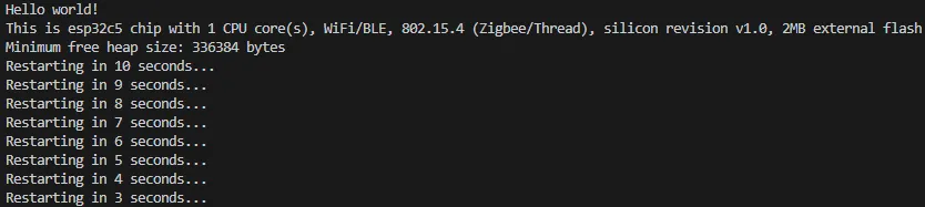
This example prints Hello world!, chip features, Flash size, and minimum free heap size to the serial port; then it outputs a restart countdown every second and reboots automatically when the countdown ends. It can be used to verify that the ESP-IDF environment, flashing path, and serial monitor are working properly.
02_RGB
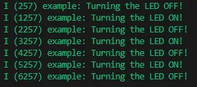
This example drives the onboard addressable RGB LED. The current sdkconfig selects the RMT driver, the data pin is GPIO27, and the blinking period is 1000 ms. The RGB value when the LED is on is (16, 16, 16).
03_UART
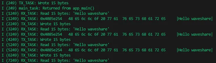
This example uses UART1 for asynchronous transmission and reception. The transmit task sends the string Hello waveshare every 2 seconds; the receive task continuously reads and outputs any received data to the serial monitor.
Hardware Connection
Short GPIO4 and GPIO5 to create a loopback (self-transmit and self-receive):
| ESP32-C5-MINI-KIT | ESP32-C5-MINI-KIT (Same Board) |
|---|---|
| GPIO4 (UART1 TX) | GPIO5 (UART1 RX) |
The current communication parameters are 115200 bps, 8 data bits, no parity, 1 stop bit, and no hardware flow control. The baud rate and task stack size can be adjusted in main/Kconfig.projbuild or via idf.py menuconfig; GPIO4 and GPIO5 are defined directly in the source code.
04_WIFI
This example connects to Wi-Fi, then sends an HTTP request to the OpenWeather API to obtain real-time weather data for Beijing and outputs the server response to the serial port. After one request completes, it waits for 30 minutes before sending the next request.
Before flashing, run idf.py menuconfig and enter the Wi-Fi SSID and password in Example Connection Configuration. When connecting to a 2.4 GHz network, make sure the router has the corresponding band enabled.
Note: The weather API URL, location, and access key are fixed in
main/main.cand use plain HTTP. Before using this in a product or on a public network, you should replace these with your own key and use HTTPS, certificate validation, and secure key management.

05_Bluetooth
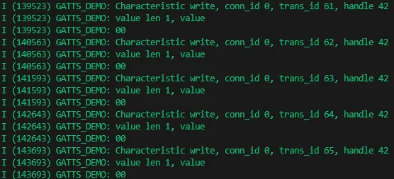
This example starts a BLE GATT Server with the advertisement name ESP_GATTS_DEMO, waiting for a phone or other BLE GATT Client to connect. The service contains two 16-bit UUIDs:
| Service UUID | Characteristic UUID | Features |
|---|---|---|
0x00FF | 0xFF01 | Read, Write, Notify, Indicate |
0x00EE | 0xEE01 | Read, Write, Notify |
Use a phone BLE debugging tool to scan and connect to ESP_GATTS_DEMO, then read or write data.
06_1.83inch_Touch_LCD_LVGL
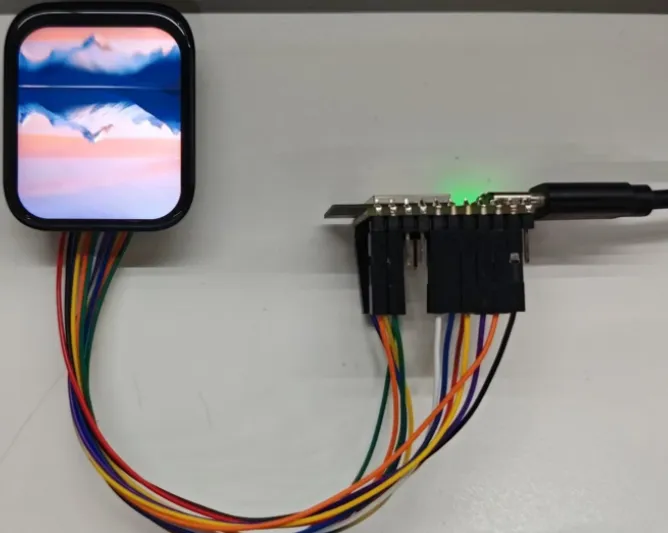
This example drives the 1.83inch Touch LCD, using the ST7789 display controller and CST816 touch controller, and displays three images based on LVGL 9. Swipe left or right on the screen to cycle through the images.
The display resolution is 240 × 284, the display interface is SPI2 with a pixel clock of 40 MHz; the touch interface is I2C0 at 400 kHz. The project depends on esp_lvgl_port, esp_lcd_touch_cst816s, and lvgl, which will be fetched by the component manager on the first build.
LCD Connections
| Function | ESP32-C5-MINI-KIT GPIO |
|---|---|
| LCD SCLK | GPIO7 |
| LCD MOSI | GPIO8 |
| LCD CS | GPIO9 |
| LCD DC | GPIO10 |
| LCD RST | GPIO15 |
| LCD Backlight | GPIO25 |
| Touch I2C SCL | GPIO24 |
| Touch I2C SDA | GPIO23 |
| Touch INT | GPIO5 |
| Touch RST | GPIO26 |
The display and touch pins for this project are defined in main/lcd_driver/lcd_driver.h and main/touch_driver/touch_driver.h. If you use a different screen or wiring, modify these definitions before rebuilding and flashing.
Resources
1. Hardware Resources
Development Board Design Files
2. Technical Manuals
ESP32-C5 Chip Official Manuals
Datasheets
3. Software Development Resources
4. Debugging Tools
Support
Monday-Friday (9:30-6:30) Saturday (9:30-5:30)
Email: services01@spotpear.com