


- sales/support
Google Chat:---
- sales
+86-0755-88291180
- sales01
sales@spotpear.com
- sales02
dragon_manager@163.com
- support
tech-support@spotpear.com
- CEO-Complaints
zhoujie@spotpear.com
- Only Tech-Support
WhatsApp:13246739196
- Purchase/Shipping/Refund
WhatsApp:13424403025
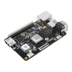
RDK-X3 User Guide
Introduction
The RDK X3 series encompasses the RDK X3 and RDK X3 Module, delivering exceptional 5Tops edge inference capabilities. Their standardized dimensions and interfaces seamlessly integrate with generic products, empowering developers to rapidly deploy intelligent products and robotic solutions.
Product parameters
| CPU | Quad-core ARM® Cortex® A53@1.5G |
| BPU | Dual-core Bernoulli Arch, 5Tops |
| Memory | 2GB/4GB LPDDR4 RAM |
| Storage | External TF card |
| Canera | MIPI CSI 2lane × 2 |
| Display interface | HDMI × 1 (up to 1920 × 1080); MIPI-DSI × 1 (up to 1920 × 1080) |
| USB Host | USB Type-A 3.0 × 1; USB Type-A 2.0 × 2 |
| USB Device | Micro USB 2.0 × 1 |
| Wired Network | RJ45 Gigabit Ethernet × 1 |
| Wireless Network | 2.4G Wi-Fi × 1, supports 802.11 b/g/n |
| Bluetooth | Bluetooth 4.1 × 1 |
| Other Interfaces | 40PIN × 1; Debug serial port × 1 |
| Power Supply | USB Type-C, 5V-2A |
| Dimensions | 85 × 56 × 20 mm |
| Operating Temperature | -25°C ~ 95°C (X3M chip temperature) |
System Installation
Software Resources
The RDK X3 development board currently supports the two system versions of Ubuntu 20.04 Server and Desktop,download the image
Please download the 2.1.1 or above version of the image.
balenaEtcher flash image
Note: When using this software to flash, try to connect directly to the USB interface of the computer, do not use external extensions, which may cause unsuccessful flashing.
1. Insert the TF card into the Card reader, connect the Card reader to the computer, and open the balenaEtcher software after the TF card is recognized.
2. Click on Flash from file and select the image file 'system_sdcard.img' you just extracted.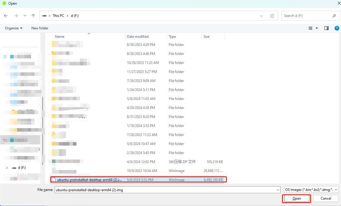
3. Click the 'Select target' button to select the disk corresponding to the TF card as the target storage device.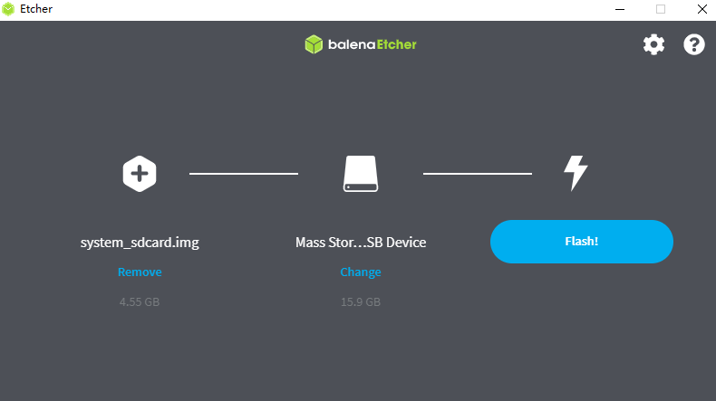
4.Click the Flash button to start flashing. When the tool prompts Flash Comple, it means that the TF card image is completed, close balenaEtcher, remove the card reader from the computer, and remove the TF card.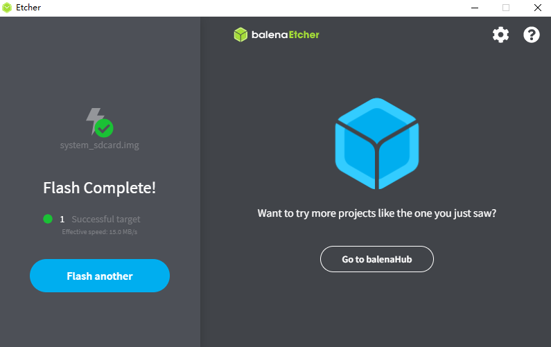
Power On
Power off RDK X3, insert the TF card into the card slot, connect the display to the HDMI interface, and power up the development board.
- Red indicator: On indicates that the hardware is powered on normally
- Green indicator: On means the system is starting, off means the system has finished starting
When the system is started for the first time, the preset toolkit in the image will be installed. The whole process takes about 1 to 2 minutes. During the installation, HDMI has no display output. After the installation is completed, the system will automatically restart and open the HDMI display output, and the boot screen will be displayed (the server system displays the horizon logo, and the desktop version displays the system desktop).
After the startup screen is displayed normally, it indicates that the system startup is complete. At this time, you can log in to the development board through serial port login and SSH login, log in with user name: sunrise and password: sunrise
If the HDMI output is not displayed for a long time (more than 2 minutes) after the development board is powered on, the development board starts abnormally. At this time, user can log in to the development board through serial port login, check the printing of the serial port during the startup process, and confirm the startup status of the development board. When the TF storage card image is abnormal, the log is as follows: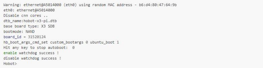
At this time, user can remake the TF storage card for system recovery.
Remote Login
The IP of device is used when using VNC and SSH to log in remotely. Therefore, users need to obtain the IP address of the development board in advance. At this time, it is recommended that users log in to the development board using a serial port and confirm the network parameters. Log in with the user name: sunrise and Password: sunrise.
Serial Port Login
Hardware Preparation
- 1. PC
- 2. RDK X3
- 3. Charging cable
- 4. 4pin cable
- 5. Serial port module
Hardware Connections
| RDK X3 | Serial Port Module |
|---|---|
Then connect the serial port module to the computer.
Note: The power cord is not connected.
Software Download
- Method 1: MobaXterm
Serial Login Operation
- Method 1: Putty serial port login
After the hardware is connected and the driver is installed, open the device manager and you will see the following ports: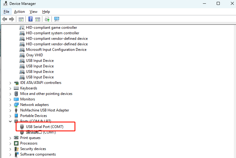
Open the putty software and configure it as shown below (based on the actually identified ports).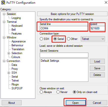
As soon as RDK X3 is Power-up, you will see a message printed in the putty window, and then you can log in.
Enter Command
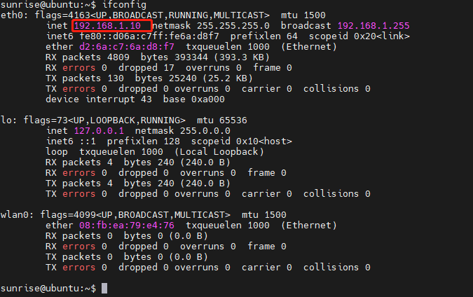
ifconfig
Get the IP address of RDK X3
ifconfig eth0 represents the Ethernet network (refers to the Ethernet cable), and the system just flashed defaults to 192.168.1.10
ifconfig wlan0 stands for WiFi network
- Method 2: MobaXterm Serial Port Login
After the hardware is connected, power on the RDK X3, open the MobaXterm software, and configure it as shown in the figure below.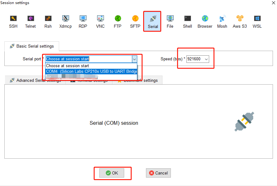
As soon as the Rising Sun X3 is powered on, you can see there is a message printed in MobaXterm , and then you can log in.
SSH Login
We need to configure the IP of the computer before SSH login
We have obtained the IP address(192.168.1.10) of RDK X3 from the serial port login
To enable communication between the computer and the RDK X3, the following steps need to be taken:
- 1. The first three sections of the IP address of the development board and the PC are the same, for example,
the development board: 192.168.1.10; the PC: 192.168.1.100 - 2. The subnet mask and gateway of the development board and PC should be consistent.
- 3. The network firewall on the PC is turned off.
Configuring the IP of computer is mainly carried out in the following steps:
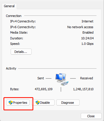
- 1. Locate the corresponding Ethernet device in the network connection and right-click to select Properties
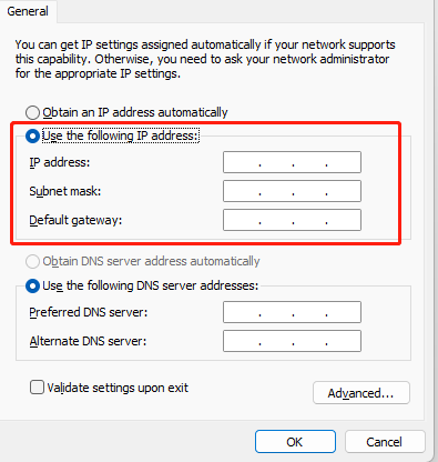
- 2. Locate the Internet Protocol version 4 option and double-click to open
- 3. Fill in the corresponding network parameters at the red box in the figure below, and click OK
MobaXterm Login
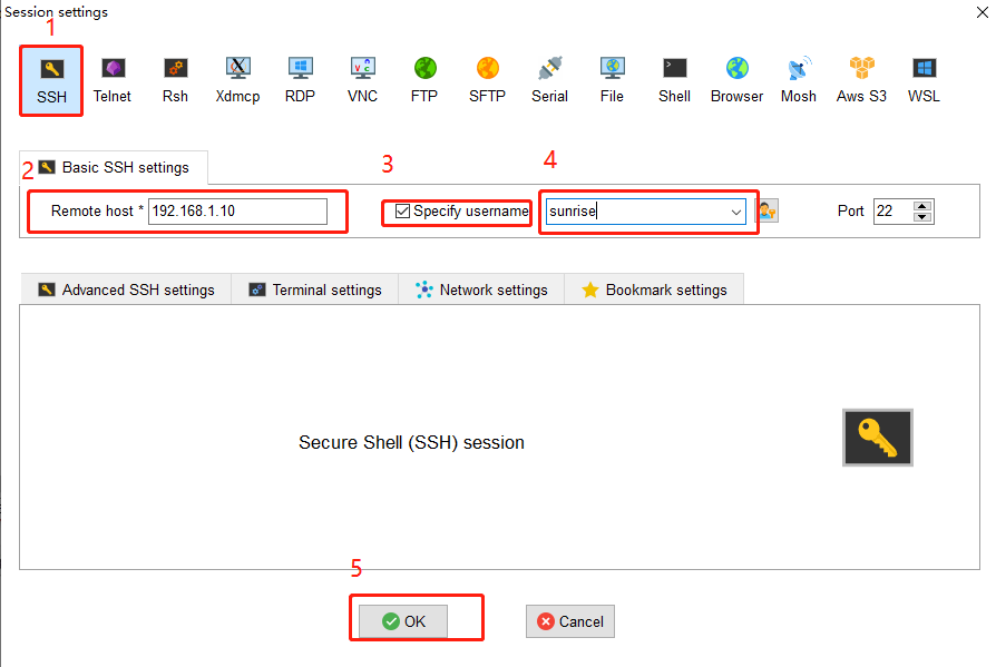
Note: Power on, enter the user name and password must be completed within 60s. If it is not completed, just enter it again within 60S.
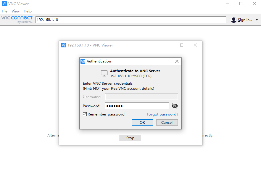
VNC Login
Open the VNC software, enter the IP address of RDK X3 in the address bar, press Enter, and configure as shown in the following image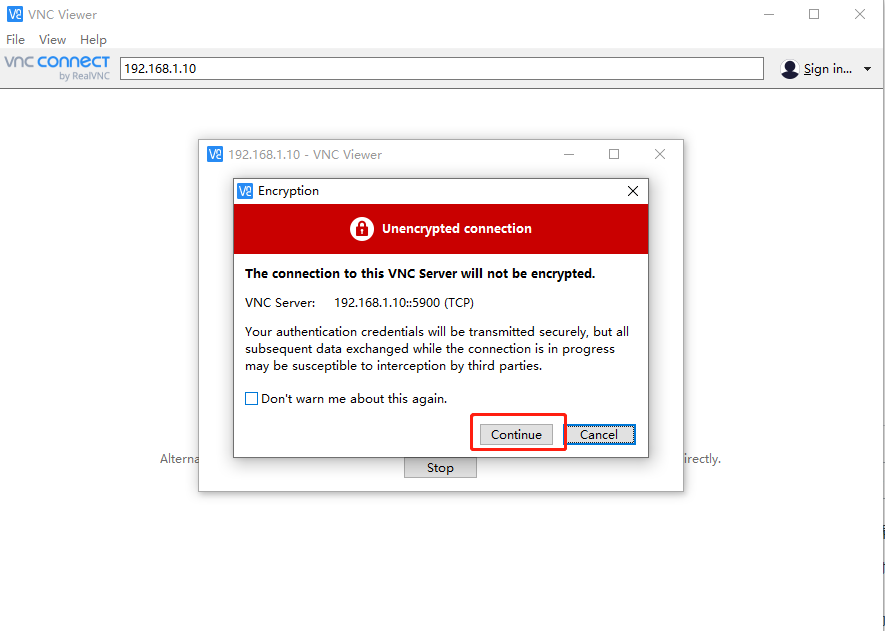
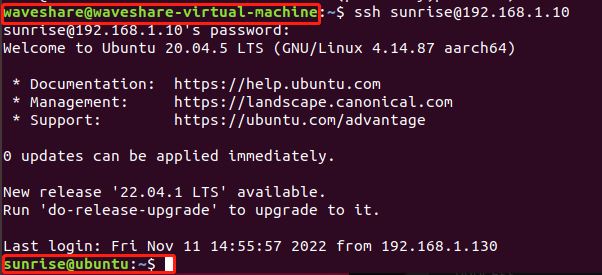
Command-line Login
ubuntu virtual machine opens the terminal to enter:
ssh sunrise@192.168.1.10
System Configuration
system update
For the safety and stability of the system, it is recommended that users update the system through the APT command after installing the system.
In the/etc/apt/source.list file, the software source list of the APT command is saved. Before installing the software, you need to update the package list with the apt command.
First, open the terminal command line and enter the following command:
sudo apt update
Secondly, upgrade all installed packages to the latest version with the following command:
sudo apt full-upgrade
Note: It is recommended to use full-upgrade command instead of the simple upgrade command, so that when the dependencies change, the dependency packages are also updated synchronously.
When the sudo apt full-upgrade command is run, the system will prompt for data download and disk usage size, but apt will not check whether there is enough disk space, it is recommended that users use command:
df-h
to check manually. In addition, the deb file downloaded during the upgrade process is stored in /var/cache/apt/archives directory, users can use command:
sudo apt clean
to delete the cache file to free up disk space.
After performing full-upgrade, it may be possible to reinstall the driver and upgrade the core of RDK X3, so it is recommended to restart the device, and the command is as follows:
sudo reboot
Wired Network Configuration
The development board network configuration is saved in the/etc/network/interfaces file, Please press the Esc key when saving when using the vim editor, and then enter
:wq!
It is recommended to use the nano editor, the installation command is as follows:
sudo apt update
sudo apt-get install nano
Static IP modification
Modify fields such as address, netmask, and gateway, you can complete the modification of the static IP configuration.
For example:
sudo vim/etc/network/interfaces
# interfaces(5) file used by ifup(8) and ifdown(8)
# Include files from/etc/network/interfaces.d:
source-directory /etc/network/interfaces.d
auto eth0
iface eth0 inet static
address 192.168.1.10
netmask 255.255.255.0
gateway 192.168.1.1
metric 700
After completing the modification, in Command-line enter
sudo systemctl restart NetworkManager
to let the configuration take effect.
Restart to update network band:
sudo reboot
Modify DHCP configuration
DHCP (Dynamic Host Configuration Protocol) is usually used in large-scale local area network environments. Its main role is to centrally manage and assign IP addresses, so that hosts in the network environment can dynamically obtain IP addresses, Gateway addresses, DNS server addresses and other information, and can improve the utilization of addresses. The DHCP network configuration of the development board is saved in the/etc/network/interfaces file. Modification of the DHCP mode can be completed by modifying the configuration related to eth0, for example the terminal enters:
sudo vim/etc/network/interfaces
Modify the following:
source-directory /etc/network/interfaces.d
auto lo
iface lo inet loopback
auto eth0
iface eth0 inet dhcp
 metric 700
When the modification is complete, in Command-line enter command
sudo systemctl restart NetworkManager
to make the configuration effective.
Restart to update network bands:
sudo reboot
Modify MAC Address Configuration
If you want to modify the default MAC address of the development board, you can add the pre-up configuration information in the/etc/network/interfaces file to specify the MAC address required by user, for example:
sudo vim /etc/network/interfaces
Modify the following:
# interfaces(5) file used by ifup(8) and ifdown(8)# Include files from /etc/network/interfaces.d:
source-directory /etc/network/interfaces.d
auto eth0
iface eth0 inet static
   address 192.168.1.10
   netmask 255.255.255.0
   gateway 192.168.1.1
   pre-up ifconfig eth0 hw ether 00:11:22:9f:51:27
When the modification is complete, in Command-line enter
sudo systemctl restart NetworkManager
to make the configuration effective.
Restart to update the network frequency band.
sudo reboot
Wireless network configuration
Ubuntu Desktop Version System
After connecting to WiFi, the indicated location in the image below will change to the WiFi style.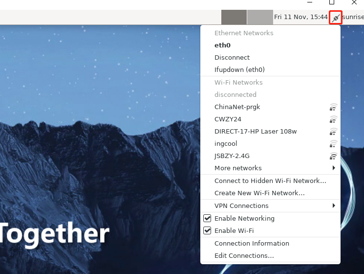
Ubuntu Server Version System
Enter the WiFi scan command:
sudo nmcli device wifi rescan
If there is an error; Scanning not allowed immediately following previous scan, it means scanning is too frequent. Please wait for a moment before scanning again. Show the scanned WIFI:
sudo nmcli device wifi list
Connect to WiFi using commands:
sudo wifi_connect "SSID" "PASSWD"
sudo wifi_connect "JSBPI" "waveshare0755"
Return the following command to indicate success, if there are other problems, follow the error prompts to modify it
If an error: No network with SSID 'WiFi-Test' found.occurs, indicating that the hotspot has not been refreshed and you can execute the following command to rescan:
sudo nmcli device wifi rescan
Wireless Networ Soft AP
Wireless networ Soft AP can be understood as WiFi hotspot on your phone.
The wifi of the AP6212 supports both soft AP and Station modes. By default, it runs in Station mode. If you want to use the soft AP function, follow the steps below to configure it.
1. Install hostapd and isc-dhcp-server
sudo apt update
sudo apt install hostapd
sudo apt install isc-dhcp-server
Configure hostapd and open:
sudo vim /etc/hostapd.conf
For hotspot configuration without a password, please add the following:
interface=wlan0
driver=nl80211
ctrl_interface=/var/run/hostapd
ssid=Sunrise
channel=6
ieee80211n=1
hw_mode=g
ignore_broadcast_ssid=0
For hotspot configuration with a password, please add the following:
interface=wlan0
driver=nl80211
ctrl_interface=/var/run/hostapd
ssid=Sunrise
channel=6
ieee80211n=1
hw_mode=gignore_broadcast_ssid=0
wpa=2
wpa_key_mgmt=WPA-PSK
rsn_pairwise=CCMP
wpa_passphrase=12345678
2. To configure isc-dhcp-server terminal, enter
sudo vim /etc/default/isc-dhcp-server
Save and exit, if the network interface is defined and used as below: INTERFACESv4 = "wlan0"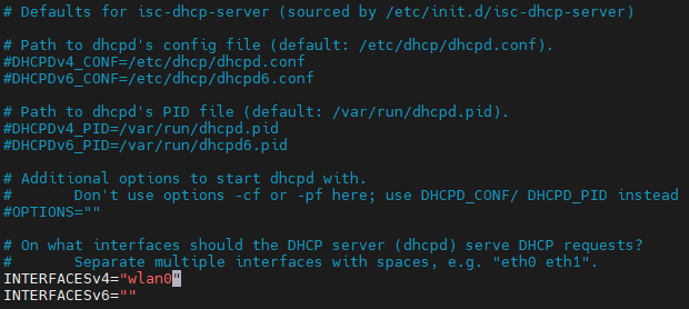
Enter the following content in the terminal:
sudo vim /etc/dhcp/dhcpd.conf
Uncomment the following fields annotation:
authoritative;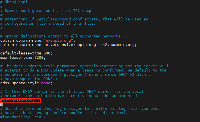
Then Enter:
sudo vim /etc/dhcp/dhcpd.conf
Add the following configuration at the end of the file:
subnet 10.5.5.0 netmask 255.255.255.0 {
 range 10.5.5.100 10.5.5.254;
 option subnet-mask 255.255.255.0;
 option routers 10.5.5.1;
 option broadcast-address 10.5.5.31;
 default-lease-time 600;
 max-lease-time 7200;}
3. Stop the wpa_supplicant service and restart wlan0
Note: Starting from this step, it is best to enter the superuser mode
For the first time to enter the Power User, follow the steps below
Set the password for entering the root user:
sudo passwd root
Then enter the password 3 times, set the password, confirm the password and confirm the second time
Enter the root user:
su root / sudo su
Then enter your password
Log out of root user:
su sunrise
Enter the following command to stop the wpa_supplicant service and restart wlan0
systemctl stop wpa_supplicant
4. Start the hostapd service
sudo hostapd -B /etc/hostapd.conf
The following information will be printed:
root@ubuntu:~# sudo hostapd -B /etc/hostapd.conf
Configuration file: /etc/hostapd.conf
Using interface wlan0 with hwaddr 08:e9:f6:af:18:26 and ssid "sunrise"
wlan0: interface state UNINITIALIZED->ENABLED
wlan0: AP-ENABLED
5. Configure the IP and subnet for the wireless interface wlan0, ensure consistency with the configuration above.
sudo ifconfig wlan0 10.5.5.1 netmask 255.255.255.0
6. Start the DHCP server, after connectting to the hotspot, an IP address between 10.5.5.100 and 10.5.5.255 will be assign to the client.
sudo systemctl start isc-dhcp-server
sudo systemctl enable isc-dhcp-server
Open your phone and connect to the hotspot named 'Sunrise'
7. Switch back to the Station mode
# stop hostapd
killall5 -9 hostapd
# Clear the address of wlan0
ip addr flush dev wlan0
sleep 0.5
ifconfig wlan0 down
sleep 1
ifconfig wlan0 up
# restart wpa_supplicant
systemctl restart wpa_supplicant
# Connect to the hotspot. For detailed instructions, please refer to the previous section'Wireless Network'
wifi_connect "JSBPI" "waveshare0755"
DNS Service
DNS (Domain Name Server) is a server that performs domain name and corresponding IP address translation. The development board DNS has been configured with the/etc/systemd/resolved.conf file management, and users can complete the DNS-related configuration by modifying the file, in which users can remove the '#' symbol in the front of the '#DNS':
1. Modify the/etc/systemd/resolved.conf file:
sudo vim /etc/systemd/resolved.conf
Add the DNS server address:
DNS=8.8.8.8 114.114.114.114
2. Enable the new DNS configuration:
sudo systemctl restart systemd-resolved
sudo systemctl enable systemd-resolved
sudo mv /etc/resolv.conf /etc/resolv.conf.bak
sudo ln -s /run/systemd/resolve/resolv.conf /etc/
CPU frequency scaling Strategy
The development board uses the CPUFreq driver in the Linux kernel to manage the CPU working state. The default state is ondemand mode. At this time, the CPU will dynamically adjust the frequency according to the load to achieve the purpose of reducing power consumption. The user can force the CPU to work at the highest frequency of 1.2GHz by the following command:
sudo bash -c 'echo performance > /sys/devices/system/cpu/cpufreq/policy0/scaling_governor'
The development board provides overclocking in the system to increase the maximum frequency of CPU from 1.2GHz to 1.5GHz. The configuration command is as follows:
sudo bash -c 'echo 1 > /sys/devices/system/cpu/cpufreq/boost'
Note that CPU’s overclocking may cause system stability problems. If you encounter stability problems, you need to turn off the overclocking function and the command is as follows:
sudo bash -c 'echo 0 > /sys/devices/system/cpu/cpufreq/boost'
Special Statement: CPU overclocking is limited to developers Geek for experimental use only. Before overclocking, it is necessary to ensure that the chip has fan thermal measures to ensure that the junction temperature of the chip can be kept below 95 degrees Celsius under long CPU operation, so as to avoid chip failure caused by the chip running for a long time under high temperature conditions. CPU overclocking will also cause some unpredictable chip reliability problems, so developers should proceed with caution. The commands for viewing the chip's current junction temperature, the running frequency of CPU, the running frequency and usage rate of BPU are as follows:
sudo hrut_somstat
Self-starting configuration
By adding a command at the end of the sudo vim/etc/rc.local file, you can achieve the function of booting and running the command automatically.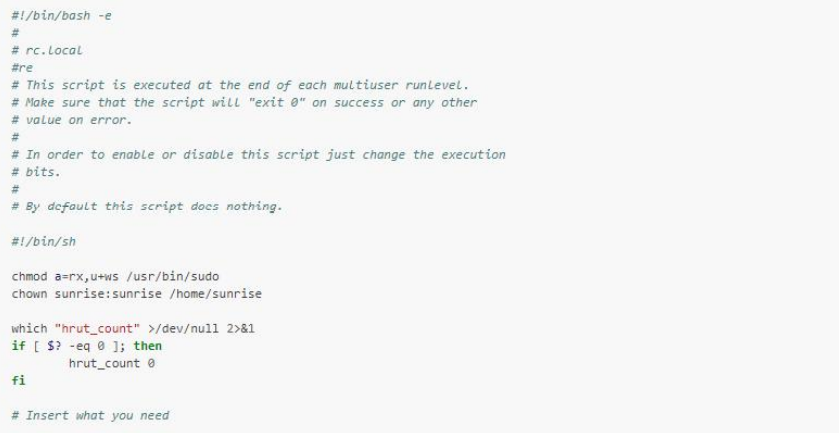
Bluetooth
Call the script to complete initialization;
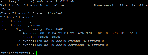
sudo startbt6212.sh
The script being called for initialization has completed the following tasks:
- Reset Bluetooth
- Create messagebus users and user groups that the dbus-daemon program needs to use when it runs
- Run brcm_patchram_plus to complete driver loading and firmware loading for Bluetooth
- Periodically check if the /sys/class/bluetooth/hci0 directory exists to verify that the Bluetooth driver is working properly
- Done setting line discpline appears indicating that Bluetooth is enabled successfully
- Execute hciconfig hci0 up to complete Bluetooth Link Up
- Execute hciconfig hci0 piscan for Bluetooth scanning, this step can be removed according to the situation
- As shown below:
- After successful execution, confirm that the following processes are running normally:
cd /usr/bin
*ls #Check if there are dbus-daemon and brcm_patchram_plus files
*cd ..#Back to previous
*cd lib/bluetooth #Go to directory
*ls #Check if there is bluetooth files
Command Line Operation
Enter the Bluetooth configuration interface in interactive mode
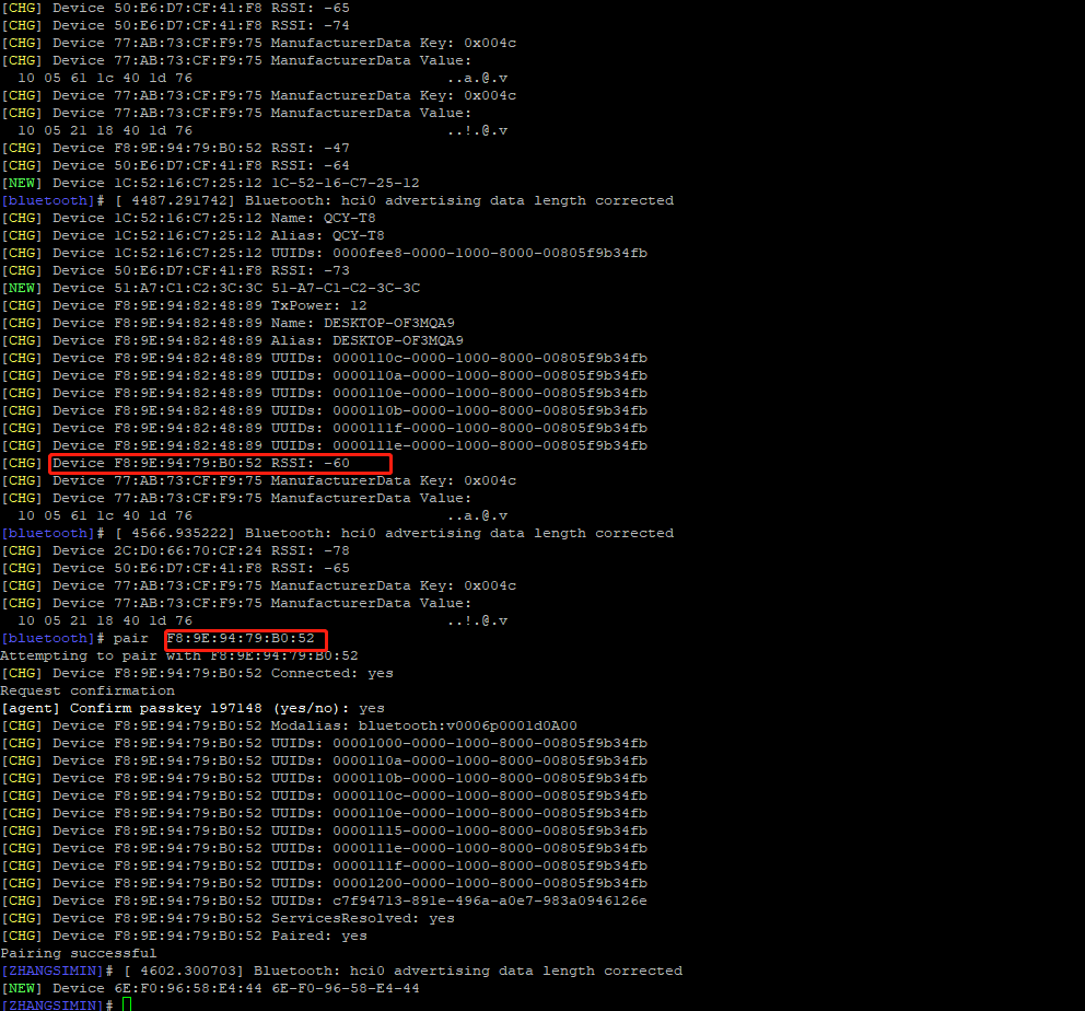
sudo bluetoothctl

Indicates Bluetooth has been recognized
Enter 'show' to view Bluetooth details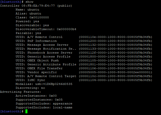
Pay attention to the status of Bluetooth Powered, Discovera (searchable)
power on          Enables Bluetooth
power off         Disables Bluetooth
discoverable on   Makes the device detectable
discoverable off  Makes the device undetectable
scan on           Start scanning nearby Bluetooth devices
scan off          Stop scanning
Pair the corresponding Bluetooth device, note that enter yes according to the prompts
pair [targetMAC]
Example: pair 9C:5A:81:3E:97:4C
After successful pairing, use the command to auto-connect the next time
trust [targetMAC]
Example: trust 9C:5A:81:3E:97:4C
Bluetoothctl Command Extension
- exit: Exit the bluetoothctl interactive interface
- help: Get a list of commands supported by bluetoothctl
- Connect: Connect the BLE device, enter connect BLE Mac to connect the specified BLE device. If the connection is successful, it will prompt connect successfully. After the first successful connection, all the properties supported by the BLE device will be displayed; if the specified device cannot be searched, it will prompt not available
- disconnect: Disconnect the device
For more information, please visit the BlueZ website:
http://www.bluez.org/
Desktop Software Opreation
Select the icon in the upper right corner or the menu bar to operate on Bluetooth
Or click Application.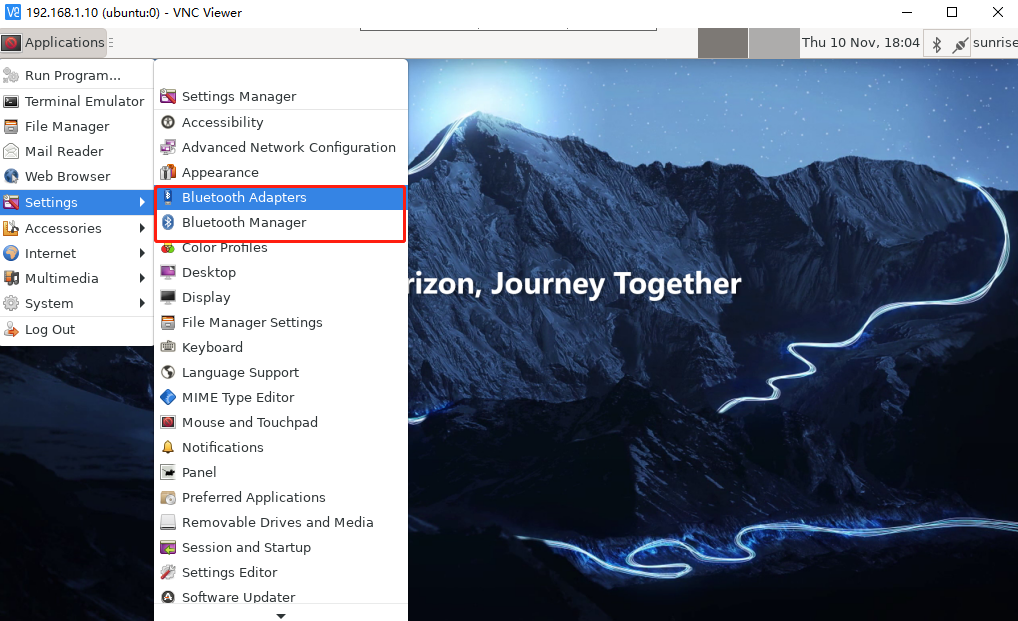
Bluetooth Adapters: used to configure native Bluetooth setting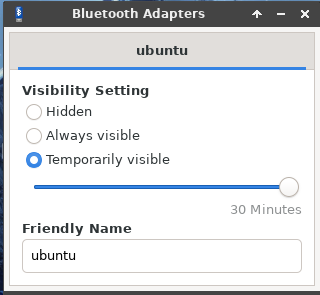
tooth Manager: used to scan Bluetooth devices and connect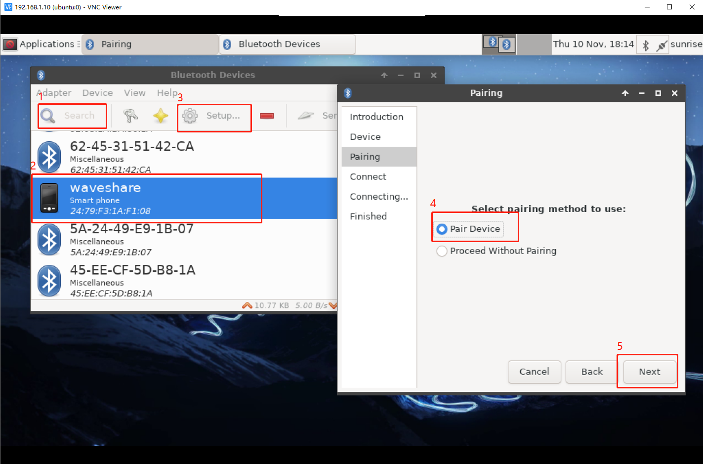
Expansion
see if the Bluetooth module is recognized:
Hciconfig-a
See the address of the Bluetooth module:
hcitool dev
Activate Bluetooth:
sudo hciconfig hci0 up
In this test, the Bluetooth module is set as the server and does not need a pairing code:
hciconfig hci0 noauth
Edit the file and turn on the Bluetooth device:
sudo vi/etc/systemd/system/dbus-org.bluez.service
Find ExecStart =/usr/lib/bluetooth/bluetoothd, change and add as:
ExecStart =/usr/lib/bluetooth/bluetoothd-c;
ExecStartPost =/usr/bin/sdptool add SP;
CSI Camera Use
Hardware Connection
To test the camera, you need to connect the X3 to an HDMI screen
Put the metal side of the cable down and connect it to the camera interface.
Camera Test
The camera interface of the RDK X3 is turned on by default, and it can be used when it is powered on. The AI demo that comes with the system can be used to test the camera, please ensure that the HDMI screen is connected and the preview screen can be displayed.
When Raspberry Pi or Jetson series cameras connectting to RDK X3, Adapter plate needs to be purchased separately.
Open the terminal and enter the following instructions:
- If you are logging in via SSH, you need to specify the output as a screen now
export DISPLAY =:0
- Test with AI demos
cd/app/ai_inference/03_mipi_camera_sample
Sudo python3 mipi_camera.py
Under normal circumstances, the camera will turn on the preview and display the image and corresponding object recognition results.
Basic Use of GPIO
Turn on the peripherals on the 40Pin pin (SPI2, I2C0, I2S0, I2S1, UART3)
Enter
sudo srpi-config
Disabled means that this feature is turned off (configured to normal GPIO)
okay means to turn on this function (use special functions)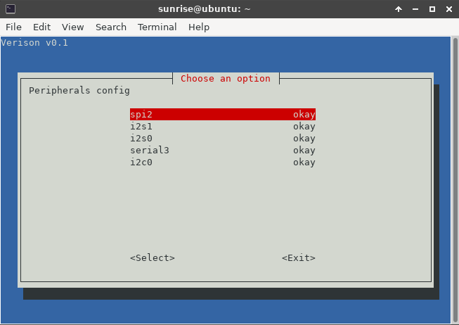
The on-board green LED light has pins of GPIO26
Using Shell Commands to Control GPIO (File IO)
The functions of the various directories and files under this directory
cd sys/class/gpio
- gpio_operation manipulates the mapping of IO port GPIO to file system through the/sys/file interface
- The directory that controls gpio is located in/sys/class/gpio
- /sys/class/GPIO/export file is used to inform the system of the GPIO pin number required for export control
- /sys/class/gpio/unexport is used to notify the system to cancel the export
- /sys/class/GPIO/gpiochipX directory stores the information of GPIO registers in the system, including the starting number base of each register control pin, the register name, and the total number of pins
- The operation steps of deriving one pin: write this number to/sys/class/gpio/export, such as pin 12, echo 12 >/sys/class/gpio/export, after the command is successful, the/sys/class/gpio/gpio 12 directory is generated, if there is no corresponding directory, it means that this pin cannot be exported
- direction file defines the direction of input and output, which can be defined as the output by the following command, and the parameters accepted by direction: in, out, high, low. high/low meanwhile set orientation to output
- value file is the numeric value of the port, which is 1 or 0
Practical Operation
1. Export GPIO105 (BCM26 pin) from kernel space into user space
sudo echo 105 >/sys/class/gpio/export
2. View GPIO18 pins
cd/sys/class/gpio/gpio105
3. Set the mode of GPIO18
sudo echo out > direction # set to output mode
sudo echo in > direction # set to input mode
4. Set the status of pins
sudo echo 1 > value # set to high
sudo echo 0 > value # set to low
5. Read the status of pins
sudo cat value # return value 0 for low state and 1 for high state
6. Read the pattern of pins
sudo cat direction # returns in as input and out as output
7. Cancel export
cd
sudo echo 105 > /sys/class/gpio/unexport
Python Example
RDK X3 has installed Python and Hobot.GPIO by default, you can import the module and view its version information.
Disable Warning Messages
The GPIO you are trying to use may already be used outside the current application. In this case, the GPIO library will warn you. It will also warn you if you try to clean before setting the mode and channel. To disable warnings, please call:
GPIO.setwarnings (False)
Set Pin Numbering
GPIO.setmode (GPIO.BOARD)
BOARD (the pin number of the 40 pin GPIO header): The serial number of physical pin, the serial number that can be seen directly on the silk screen on the hardware, is physically exactly one-to-one correspondence.
BCM (the Broadcom SoC GPIO numbers): BCM is named according to the GPIO rules of Broadcom SoC.
CVM uses a string instead of a number, corresponding to the signal name of the CVM/CVB connector.
The number corresponding to the SOC is the GPIO pin serial number of Horizon Sunrise X3M chip, which corresponds one-to-one with the chip data manual.
Setting Pins
The GPIO channel must be set up before it can be used as an input or output. To configure a channel as an input, call:
# (where the channel is based on the pin numbering pattern discussed above)
GPIO.setup (channel, GPIO.IN)
Setting the output:
GPIO.setup (channel, GPIO.OUT)
You can also specify an initial value for the output channel:
GPIO.setup (channel, GPIO.OUT, initial = GPIO.HIGH);
When a channel is set to output, multiple channels can be set at the same time:
# Add as many channels as needed. You can also use tuples:(18, 12, 13)
channels = [18, 12, 13]
GPIO.setup (channels, GPIO)
Configure Output Pin Status
GPIO.output (channel, state)
state can be GPIO.LOW or GPIO.HIGH.
Get the Status Of the Input Pin
GPIO.input (channel)
It returns either 0 or 1. 0 stands for GPIO.LOW and 1 stands for GPIO.HIGH.
Clean Pin Occupancy
Release all pins
GPIO.cleanup ()
Only clear specific channels
# Clear a single channel
GPIO.cleanup (channel)
# Clear a set of channels
GPIO.cleanup ((channel1, channel2))
GPIO.cleanup ([channel1, channel2])
View the Status of the Pin
GPIO.gpio _ function (channel)
The function returns either IN or OUT.
Edge Detection and Interruption
Edge detection function
This function blocks the calling thread until a supplied edge is detected.
GPIO.wait_for_edge (channel, GPIO.RISING)
After this function is called, skim directly, and need to be used with other functions
GPIO.add_event_detect(channel, GPIO.RISING)
GPIO.RISING: rising edge;
GPIO.FALLING: falling edge;
GPIO.BOTH: Edge (up + down);
Set the time of wait timeout
# Timeout is in milliseconds
GPIO.wait_for_edge(channel, GPIO.RISING, timeout=500)
The function returns the channel on which an edge was detected, or None if a timeout occurred.
event_detected() function
This function can be used to periodically check whether an event has occurred since the last call.
GPIO.add_event_detect (channel, GPIO.RISING)
If GPIO.event_detected (channel):
print ("Rising edge event detected")
Call the callback function when edge function is detected
This functionality can be used to run a second thread for the callback function. Therefore, callback functions can run concurrently with your main program in response to edge events.
# Define callback function
Def callback_fn (channel):
print ("Callback called from channel s" channel)
# Add rising edge detection
GPIO.add_event_detect (channel, GPIO.RISING, callback=callback_fn)
You can also add multiple callbacks if you want, noting that the two callback functions run sequentially
Def callback_one (channel):
print ("First Callback")
Def callback_two (channel):
print ("Second Callback")
GPIO.add_event_detect (channel, GPIO.RISING)
GPIO.add_event_callback (channel, callback_one)
GPIO.add_event_callback (channel, callback_two)
De-shaking time to prevent misoperation
# De-shaking time set in milliseconds
GPIO.add_event_detect (channel, GPIO.RISING, callback=callback_fn, bouncetime = 200)
Close interrupt
Edge detection can be removed if it is no longer required
GPIO.remove_event_detect (channel)
PWM
The RDK X3's 40 Pin has two PWM output pins:
PWM0: 33 (BOARD), 13 (BCM), 4 (x3 pin number);
PWM1: 32 (BOARD), 12 (BCM), 25 (x3 pin number)
shell command control
PWM0
Export PWM0 to User Space
echo 0 >/sys/class/pwm/pwmchip0/export
Time (ns) to set PWM for one cycle
Note: This time range for PWM waves is recommended from 50 to 21000
echo 20000 >/sys/class/pwm/pwmchip0/pwm0/period
Duty cycle setting, which is the time when the PWM is on (default is high)
echo 10000 >/sys/class/pwm/pwmchip0/pwm0/duty _ cycle
# In the pwm signal, whether the low level is turned on or the high level is turned on, here it is set to the normal polarity, that is, high is on.
# echo "normal" >/sys/class/pwm/pwmchip0/pwm0/polarity
Enable PWM Wave to output
echo 1 >/sys/class/pwm/pwmchip0/pwm0/enable
Disabling PWM Wave to output
echo 0 >/sys/class/pwm/pwmchip0/pwm0/enable
Cancel Export
echo 0 >/sys/class/pwm/pwmchip0/unexpor
PWM4
Similar to PWM0
pwmchip3 + PWM1 = PWM4;
echo 1 >/sys/class/pwm/pwmchip3/export
echo 20000 >/sys/class/pwm/pwmchip3/pwm1/period
echo 10000 >/sys/class/pwm/pwmchip3/pwm1/duty _ cycle
echo 1 >/sys/class/pwm/pwmchip3/pwm1/enable
echo 0 >/sys/class/pwm/pwmchip3/pwm1/enable
echo 1 >/sys/class/pwm/pwmchip3/unexport
Expansion
Properties under pwmchip0/3 directory
device
export: export the pwm channel, which must be exported before use
npwm: There are several PWM outputs under the PWM controller
power
subsystem
uevent
unexport: Cancels exporting PWM channels
Properties under pwm* directory
Period      period
Duty cycle  duty _ cycle
polarity    polarity
Period: in nanoseconds, 10000000000 ns = 1s
Duty cycle: The ratio of high and low levels
Polarity: whether the low level is the on state or the high level is the on state, generally normal, that is, the high level is the on state
(inverted, normal)
python example
The Hobot.GPIO library only supports PWM on pins with additional hardware PWM controllers. Unlike the RPi.GPIO library, the Hobot.GPIO library does not implement software simulation PWM, and the RDK X3 supports 2 PWM channels.
Import Hotbot.GPIO
sunrise@ubuntu:~$ sudo python3
Python 3.8.10 (default, Mar 15 2022, 12:22:08)
Type "help", "copyright", "credits" or "license" for more information.
>>> import Hobot.GPIO as GPIO
>>> GPIO.VERSION
'0.0.2'
>>> GPIO.model
'X3PI'
Config:
Configure the method of pin numbering:
GPIO.setmode(GPIO.BOARD)
Configure the output pin and the frequency of the output PWM (48KHz ~ 192MHz)
p = GPIO.PWM(output_pin, 48000)
Configure initial duty cycle (0-100)
p.start(val)
Dynamicly adjust duty cycle (0-100)
p.ChangeDutyCycle(val)
Stop outputting PWM waves
p.stop()
Clean pin occupancy
GPIO.cleanup()
Example Presentation
Run Command:
sudo python3 test_PWM.py
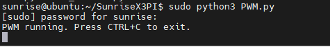
Description of the test: Open the PWM channel specified by output_pin, the initial duty cycle is 25%, first increase the duty cycle by 5% every 0.25 seconds, and then reduce the duty cycle by 5% every 0.25 seconds after reaching 100%. When the waveform is normally output, you can use an oscilloscope or the logic analyzer to measure the output signal and observe the waveform.
Serial Port
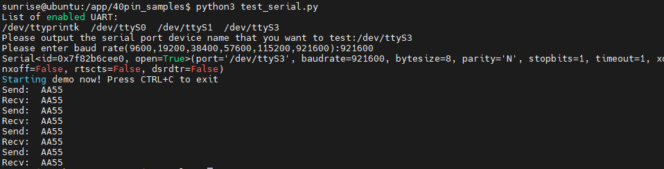
RDK X3 enables UART3 by default on 40PIN, physical pin numbers 8 and 10, IO voltage 3.3 V.
Note: Only serial port 3 (/dev/ttyS3) exists on the 40Pin interface; serial port 1 (/dev/ttyS0) is the system debug port, and it is not recommended to test it until its role is understood.
Shell Command Control
Basic instruction
View the properties of serial port :
sudo stty -F /dev/ttyS3
View all parameters
sudo stty -F /dev/ttyS3 -a
Set the baud rate of the serial port(default is 9600):
Sudo stty-F/dev/ttyS3 speed 115200
115200 baud rate, 8 data bits, 1 stop bit and no check bit
Sudo stty-F/dev/ttyS3 speed 115200 cs8-parenb-cstopb
Using serial port to send data:
sudo echo "afafsadf" >/dev/ttyS3
Using serial port to receive data (will add two characters to the received data and send it back):
sudo cat/dev/ttyS3
Extension: Read the data and save to a txt text file:
sudo cat /dev/ttyS3 > ttyS3_output.txt
Send data, then start receiving data
sudo echo "asdasdasdas" >/dev/ttyS3 cat/dev/ttyS3
Remove the serial port echo:
Stty-F/dev/ttyS3-ech0
After executing this command, the serial port will only print out when it detects a newline.
When reading serial port data, the number of lines to read is specified. For example, specify the first five columns of data.
cat/dev/ttyS3 head-n 5
Python sample program
Loopback test:
Connect TXD and RXD on the hardware, that is, connect pins 8 and 10, and then run the test program to perform write and read operations. The expected result is that the read data is exactly the same as the written data.
Run the sample program:
Sudo python3 test_serial.py
SPI
The RDK X3 leads out the SPI2 bus of the Horizon Sunrise X3 chip on the physical pins 19, 21, 23, and 24 on the 40Pin, supports one chip selection, and the IO voltage is 3.3 V.
Python
Download library:
sudo apt-get update
sudo apt-get install python-pip
pip install spidev
# Import spidev module
import spidev
# Create an object of the spidev class to access spidev-based Python functions
spi = spidev.SpiDev ();
# Open spi bus handle
spi.open (int (spi _ bus), int (spi _ device))
# int (spi _ bus): Sets the bus number of spi (0, 1, 2)
# int (spi _ device): Set selection (0, 1)
# Set the frequency of spi to 12MHz
Spi.max _ speed _ hz = 120000000

# Send a few data and read back is also a few data
resp = spi.xfer2 ([0x55, 0xAA])

# Release corresponding SPI
spi.close ()
spi.readbytes (n) # reads n bytes from a spi device
spi.writebytes (list of values) # writes a list of data to a spi device
Spi.writebytes 2 (list of values) # accepts large lists and supports numpy byte arrays
spi.xfer (send_list) # transfer data
spi.xfer2 (send_list) # transfer data, list data cannot exceed 4096 bytes
spi.xfer3 (send_list) # accepts large lists and supports numpy byte arrays
Configuration
Max_speed_hz    # the maximum frequency of communication clock
mode            # spi mode 0b00~0b11;
No_CS           # sets whether the SPI_NO_CS flag uses CS
threewire       # shared SI/SO signal
lsbfirst        # guess low is priority
loop
cshigh          # guesses that in CS high is effective;
bits_per_word
I2C
Detect I2C Devices
Sudo i2cdetect-y-r 1
Sudo i2cdetect-y-r 0
This command will start the I2C detection circuit, and the devices that are actually connected to the circuit will be displayed, but the devices that are not linked to the circuit will not be displayed, and the 7-bit I2C address will be detected.
sudo ls/dev/i2c-*
List all open I2C. RDK X3 has only two I2C hardware
/dev/i2c-0/dev/i2c-1
Baud rate of I2C
View the transfer rate for I2C
sudo cat /sys/module/i2c_bcm2708/parameters/baudrate
Modify the baud rate
sudo nano/boot/config.txt
Add a line with dtparam=i2c1_baudrate=50000 (assuming we set it to 50khz).
sudo reboot
To get the current baud rate:
sudo cat/sys/module/i2c _ bcm2708/parameters/baudrate
Set baud rate:
sudo emacs/etc/modprobe.d/custom.conf
Adding a row of settings:
Options i2c_bcm2708 baudrate = 100000
After setting, a restart is required to take effect.
Raspberry Pi Library
import smbus
Used to confirm which bus to use: Use IIC bus 1
self.i2c = smbus.SMBus (1)
Python Example
pip install smbus2
Call: import smbus

Call the IIC1 of Raspberry Pi
self.i2c = smbus.SMBus (1)

Set the address of Raspberry Pi
self.address = address;

Read a single byte from the device.
read_byte(i2c_addr,force=None)

Read a single byte from the specified register.
read_byte_data(i2c_addr,register,force=None)

Read a block of up to 32 bytes from the specified register.
read_block_data(i2c_addr,register,force=None)

Read a block of byte data from a specified register
read_i2c_block_data(i2c_addr,register,length,force=None)

Read a single word (2 bytes) from the specified register
read_word_data(i2c_addr,register,force=None)

Write a single byte to the device.
write_byte(i2c_addr,value,force=None)

Write a byte to the specified register.
write_byte_data(i2c_addr,register,value,force=None)

Write a block of byte data to the specified register.
write_block_data(i2c_addr,register,data,force=None)
The data sent is in the following format:

Address, the number of register, the quantity of data , data

Write a block of byte data to the specified register.
write_i2c_block_data(i2c_addr,register,data,force=None)

Write a byte to the specified register.
write_word_data(i2c_addr,register,value,force=None)

Perform fast transactions. If unsuccessful, throw IOError.
write_quick(i2c_addr,force=None)

Cancel the use/occupation of IIC
close ()
Access I2C devices using the SMBus Library
The I2C bus can be accessed in a Python script using the SMBus library on RDK X3. SMBus is a subset of I2C interfaces. The Python library of SMBus can be used to communicate with I2C-based devices.
Run the following command to install the SMBus library on RDK X3:
sudo apt-get install python-smbus
In a Python script, you can import the SMBus library with the following statement:
import smbus
After importing the SMBus library, you must create an object of the SMBus class using the SMBus()method. The SMBus()method takes the port number of I2C as a parameter and must be used in an assignment statement to create an SMBus object. It has the following syntax:
<Object_name> = smbus.SMBus(I2C_Port_Number)
Here is a working example of creating an SMBus object:
i2c-bus = smbus.SMBus (1)
Note: To use the latest SMBus2 library, install it using pip by running the following command:
pip install smbus2
In a Python script, you can import the SMBus2 library with the following statement:
from smbus2 import SMBus, i2c_msg
You can create an object of the SMBus class using the smbus2.SMBus() method, as follows:
i2c-bus = smbus2.SMBus (1)
The smBus2 library has two classes--SMBus and i2c_msg. The class of SMBus supports the following methods:
SMBus.SMBus ()/smbus2. SMBus ()   -Creates an SMBus object in a Python script.
open (bus)  -Opens the given i2c bus.
close ()  -closes the I2C connection.
Serial data from an I2C slave can be read in bytes, words, or blocks of bytes. In some I2C slave devices, the master device needs to access serial data from a specific register. The following methods for reading serial I2C data from a slave device are available in the SMBus2 library:
read_byte(i2c_addr,force=None)  -reads a single byte from the device.
read_byte_data(i2c_addr,register,force=None)  -reads a single byte from the specified register.
read_block_data(i2c_addr,register,force=None  -reads a block of up to 32 bytes from a given register.
read_i2c_block_data(i2c_addr,register,length,force=None)  -reads a block of byte data from a given register.
read_word_data(i2c_addr,register,force=None)  -reads a single word (2 bytes) from a given register.
Similarly, data can be written to the I2C slave in bytes, words, or blocks of bytes. In some I2C slave devices, data must be written to specific registers. The following methods for writing serial I2C data from a slave device are available in the SMBus2 library:
write_byte(i2c_addr,value,force=None)  -Writes a single byte to the device.
write_byte_data(i2c_addr,register,value,force=None)  -Writes a byte to a given register.
write_block_data(i2c_addr,register,data,force=None)  -Writes a block of byte data to a given register.
write_i2c_block_data(i2c_addr,register,data,force=None)  -Writes a block of byte data to a given register.
write_word_data(i2c_addr,register,value,force=None)  -Writes a byte to the given register.
write_quick(i2c_addr,force=None)  -Performs a fast transaction. If unsuccessful, throw IOError.
The following methods can be used to manage the processes of SMBus and combine read/write operations of I2C bus:
process_call(i2c_addr,register,value,force=None)  -Executes an SMBus process call, sends a 16-bit value and receives a 16-bit response
block_process_call(i2c_addr,register,data,force=None)  -Sends a variable-size data block and receives another variable-size response.
i2c_rdwr(*i2c_msgs)  -Combines a series of i2c reads and writes in a single transaction.
USB Usage
USB Interface Description
RDK X3 provides a USB interface. Through USB HUB and hardware switching circuit, it expands one USB3.0 Type A (interface 6), two USB3.0 Type A (interface 5), and one Micro USB 2.0 (interface 4).
| Type of interface | Sequence number of interface | Number of Interfaces | Interface description |
|---|---|---|---|
| Micro USB2.0 | Interface 4 | 1 | USB Device mode, which is used to connect the host computer to realize ADB, Fastboot, UVC and other functions |
| USB 2.0 Type A | Interface 4 | 2 | USB Host mode for accessing USB 2.0 peripherals |
| USB 3.0 Type A | Interface 6 | 1 | USB Host mode for accessing USB 3.0 peripherals |
The development board realizes the automatic switching of USB master-slave mode through the hardware circuit, and the user does not need to care about the USB master-slave mode, but only needs to connect the device according to the logic in the above table.
It should be noted that the development board is prohibited from using USB Host and Device interfaces at the same time, otherwise it will cause abnormal functions.
U disk mount
The directory of USB disk mount is /media
sda1: First USB disk mount path
sdb1: Second USB disk mount path
sdcard1: RDK X3 itself system disk path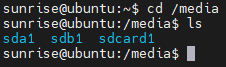
USB serial port adapter board
The USB 2.0/3.0 Type A interface of the development board supports the function of the USB serial port adapter board, which can automatically detect the access of the USB serial port adapter board and create a device node /dev/ttyUSB* or /dev/ttyACM* (the asterisk represents the number starting from 0). User can refer to Serial Portchapter to use the serial port.
USB camera
Enter in terminal, check the changes before and after insertion, and detect whether the camera is recognized
ls/dev/video *
Enter in terminal, check if the camera is working properly
Sudo v4l2-ctl-d/dev/video8 --all
Ubuntu Server Mirroring Operations
Desktop VNC Installation First
Install the xfce4 desktop with the following command:
sudo apt update
sudo apt install xfce4 xfce4-goodies xorg dbus-x11 x11-xserver-utils
Install the VNC server with the following command
sudo apt install tightvncserver
After the installation is complete, check if the vnc service has started using the following command:
ps -ef | grep vnc
If it starts normally, you can see that port 5900 is being monitored
Universal Operation
Log on to the VNC host and install ffmpeg
sudo apt install ffmpeg
Before and after connecting the USB camera, use the following command to view the current video device and determine the device number of the camera:
ls/dev/video*
Enter command to start camera
sudo ffplay/dev/video8
Information
Official Information
Applicable peripheral module
USB expansion module
SIM/GPS module
Display screen
- 7HP-CAPQLED
- 10.1inch HDMI LCD (E)
- 10.1HP-CAPQLED
- 11.6inch HDMI LCD (H)
- 13.3inch HDMI LCD (H)
- 15.6inch HDMI LCD
- 15.6inch HDMI LCD (H)
- 15.6HP-CAPQLED
Camera Module
USB Interface
CSI Interface
5-megapixel OV5647 Module Camera
- RPi Camera (B)
- RPi Camera (D)
- RPi Camera (F)
- RPi Camera (G)
- RPi Camera (H)
- RPi Camera (I)
- RPi Camera (M)
- RPi FPC Camera
- RPi FPC Camera (B)
- RPi IR-CUT Camera
- RPi IR-CUT Camera (B)
- OV5647-70 5MP OIS Camera
8-megapixel IMX219 Module Camera
- IMX219-77 Camera
- IMX219-77IR Camera
- IMX219-120 Camera
- IMX219-160 Camera
- IMX219-160IR Camera
- IMX219-160 IR-CUT Camera
- IMX219-170 Camera
- IMX219-200 Camera
12.3-megapixel IMX477 Module Camera
Usage
Supported Modules
Audio Module
Software
FAQ
Question:What is the working temperature range of the board?
Question:What is the root password?
Question:Does RDK X3 support target tracking (yolov5 plus deepsort)?
Question:Does this board support pytorch? Can I run a deep learning model trained by myself?
Question:Is there any module with lithium battery that can be used?
Question:Can this board support multiple people for human posture detection? How much FPS?
Question:If RDK X3 uses a usb camera, which system is better, server or desktop?
Question:Can RDK X3 can support solid state?
Question:Is there any POE module that can be used in RDK X3?
Question:The method for RDK X3 to deploy YOLOv5.
Support
Monday-Friday (9:30-6:30) Saturday (9:30-5:30)
Email: services01@spotpear.com
[Tutorial Navigation]
- Introduction
- Product parameters
- System Installation
- Remote Login
- System Configuration
- system update
- Wired Network Configuration
- Wireless network configuration
- DNS Service
- CPU frequency scaling Strategy
- Self-starting configuration
- Bluetooth
- CSI Camera Use
- Basic Use of GPIO
- Using Shell Commands to Control GPIO (File IO)
- Python Example
- Disable Warning Messages
- Set Pin Numbering
- Setting Pins
- Configure Output Pin Status
- Get the Status Of the Input Pin
- Clean Pin Occupancy
- View the Status of the Pin
- Edge Detection and Interruption
- PWM
- Serial Port
- SPI
- I2C
- USB Usage
- Information
- Official Information
- Applicable peripheral module
- Display screen
- Camera Module
- Software
- FAQ
- Question:What is the working temperature range of the board?
- Question:What is the root password?
- Question:Does RDK X3 support target tracking (yolov5 plus deepsort)?
- Question:Does this board support pytorch? Can I run a deep learning model trained by myself?
- Question:Is there any module with lithium battery that can be used?
- Question:Can this board support multiple people for human posture detection? How much FPS?
- Question:If RDK X3 uses a usb camera, which system is better, server or desktop?
- Question:Can RDK X3 can support solid state?
- Question:Is there any POE module that can be used in RDK X3?
- Question:The method for RDK X3 to deploy YOLOv5.
- Support