- sales/support
Google Chat:---
- sales
+86-0755-88291180
- sales01
sales@spotpear.com
- sales02
dragon_manager@163.com
- support
tech-support@spotpear.com
- CEO-Complaints
zhoujie@spotpear.com
- Only Tech-Support
WhatsApp:13246739196
- Purchase/Shipping/Refund
WhatsApp:13424403025
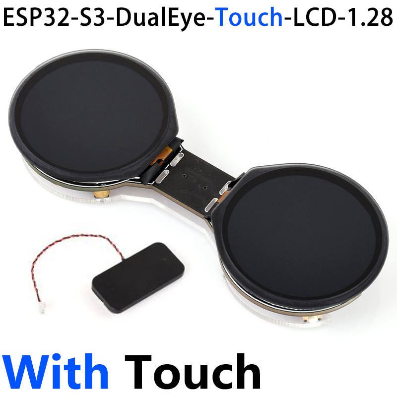
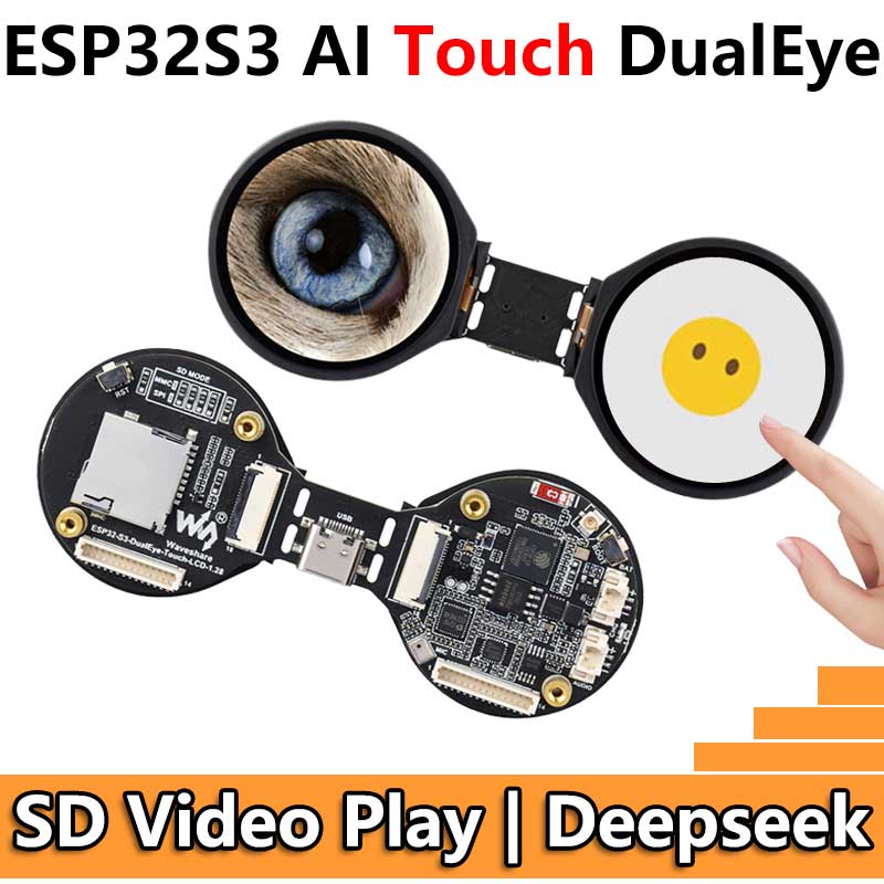
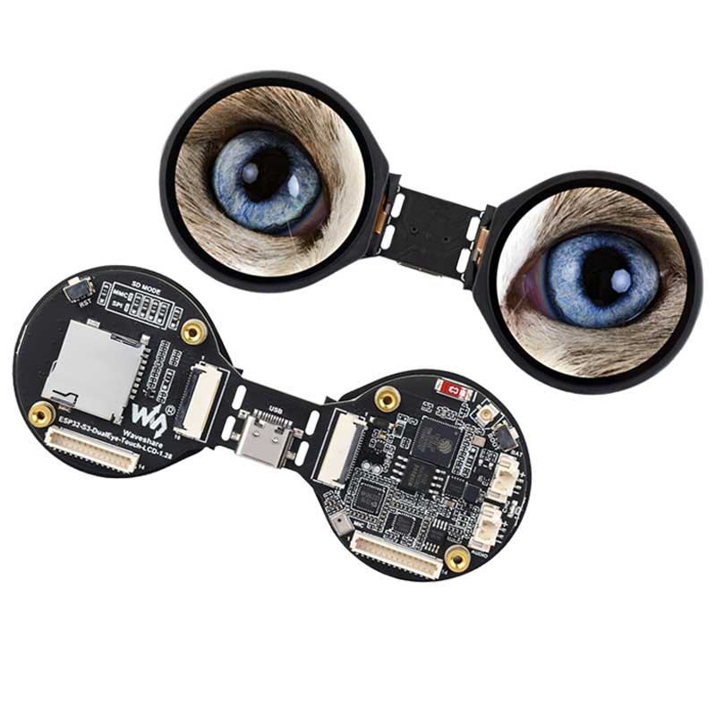
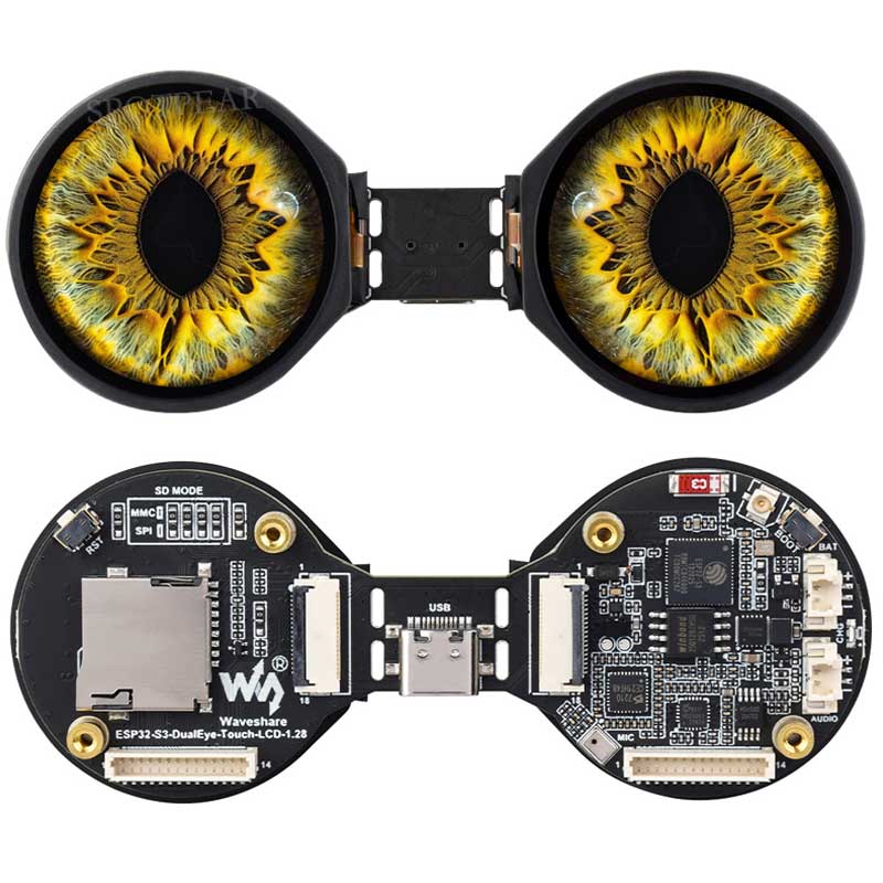
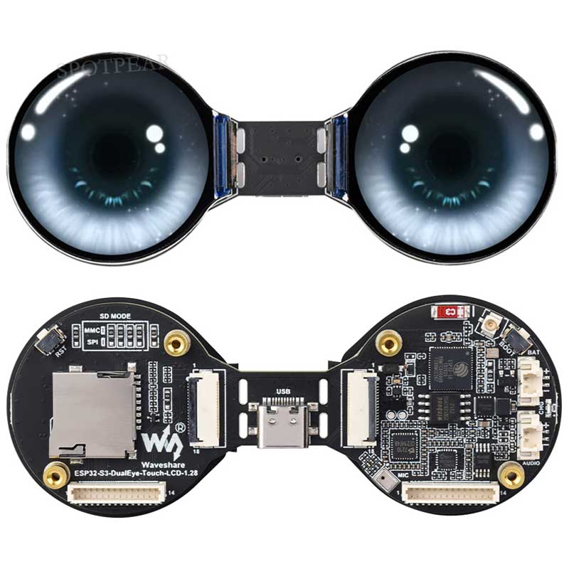
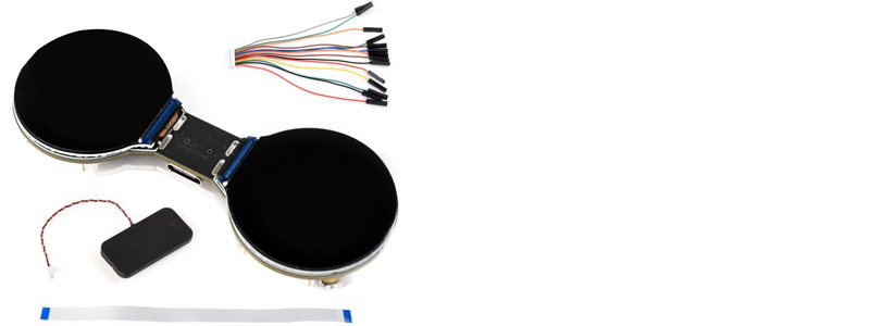
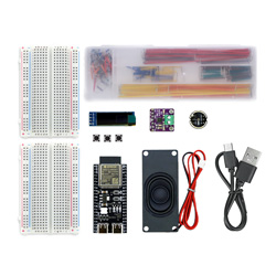
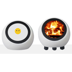
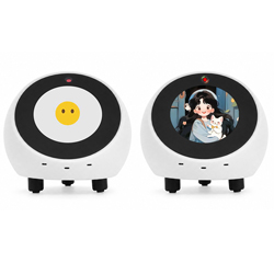
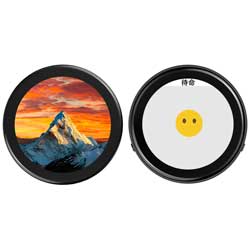
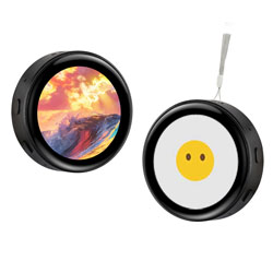
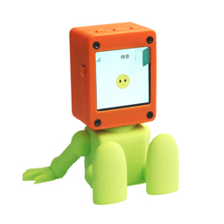
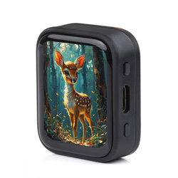
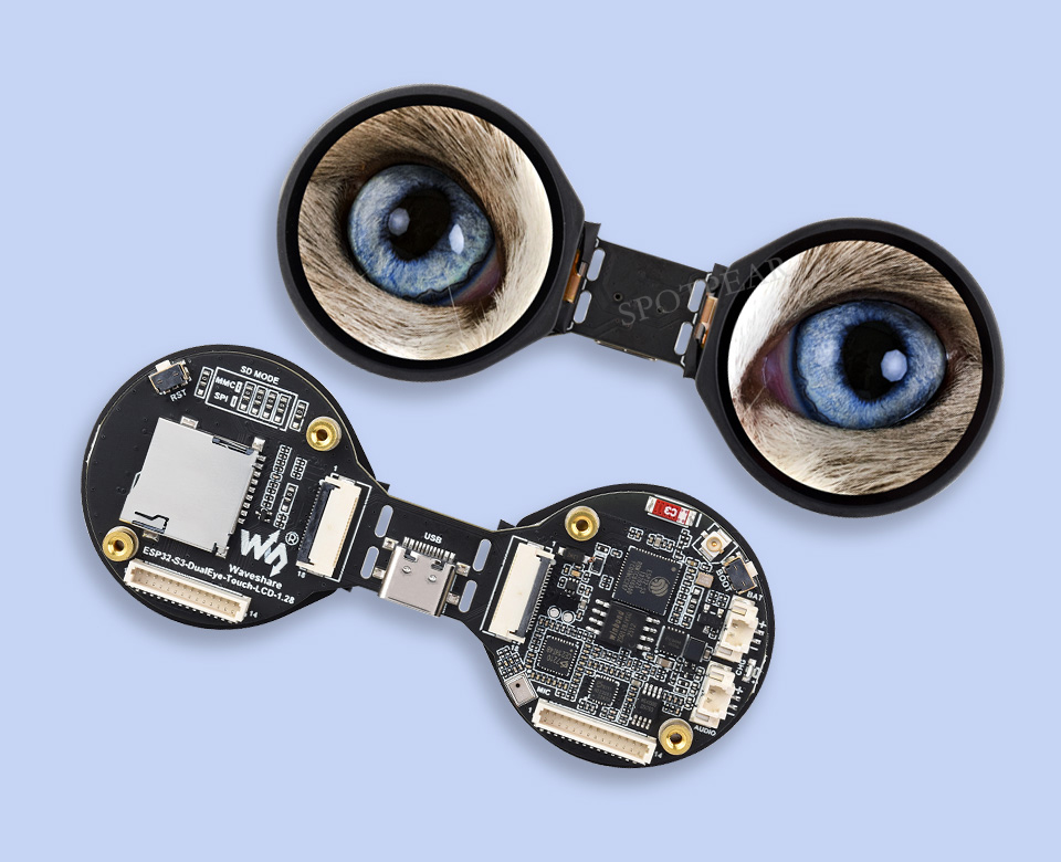
ESP32-S3 AI Electronic Eye Development Doard DualEye TouchEye 1.28 inch TouchScreen LCD Round Display N16R8 Toy Doll Robot
$29.9
ESP32-S3 dual-core 240MHz DualEye AIoT development board with two 1.28-inch IPS screens, 240×240 pixels, and Wi-Fi/Bluetooth 5 support
EPS32 DeepSeek AI Recommend
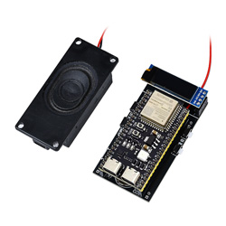
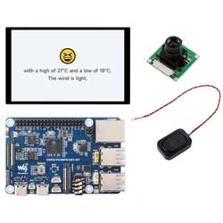
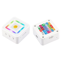
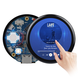
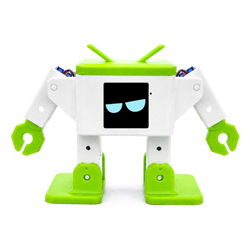
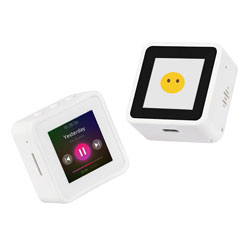
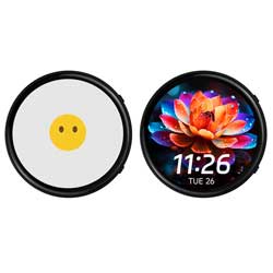
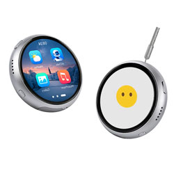
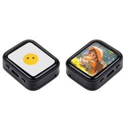
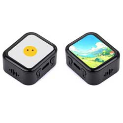
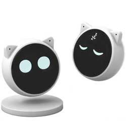
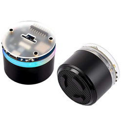
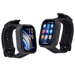
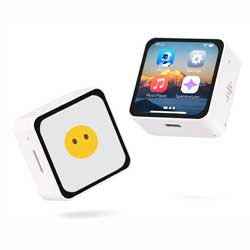
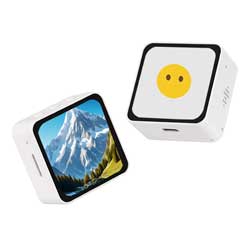
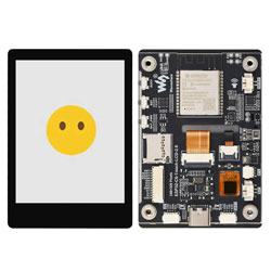
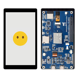
ESP32-S3 DualEye AIoT Development Board
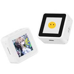
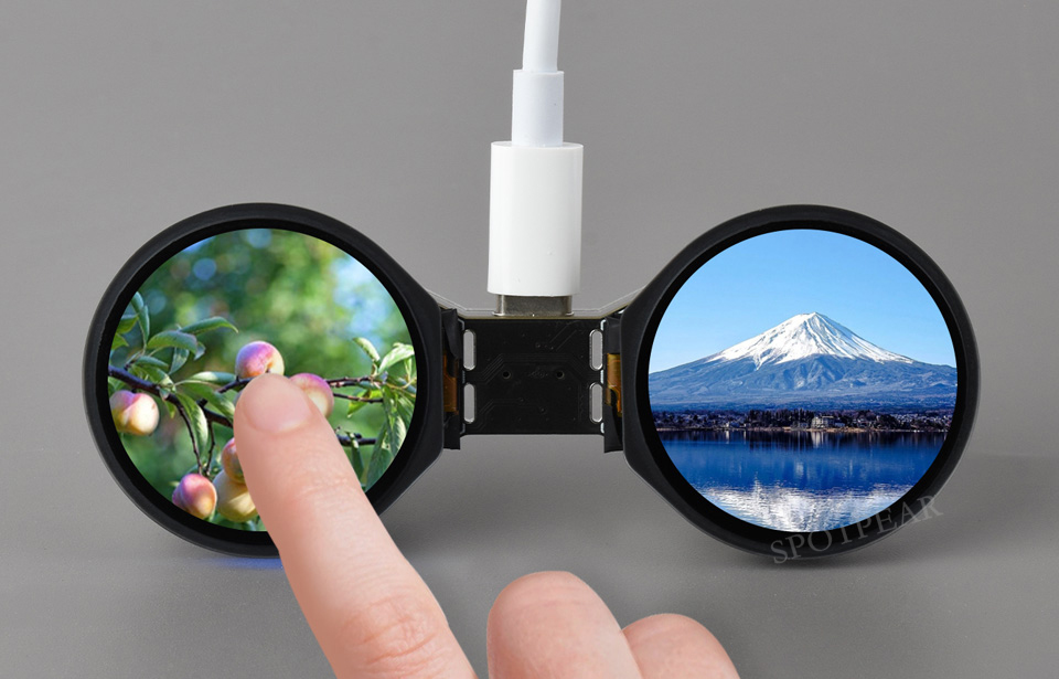
DualEye IPS screen, 1.28 inches, 240 × 240 pixels, SPI interface communication
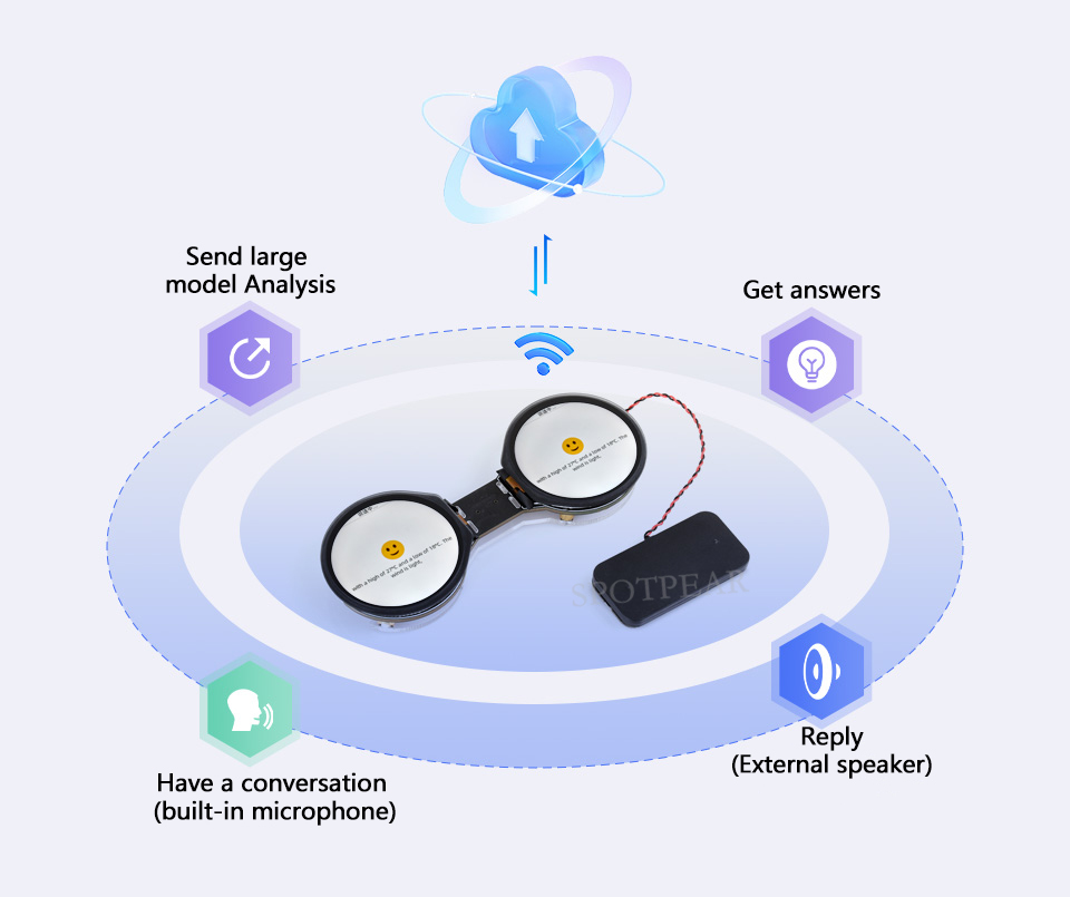
Supports AI voice dialogue, onboard SD card slot, lithium battery port and DIY port, etc.
Features
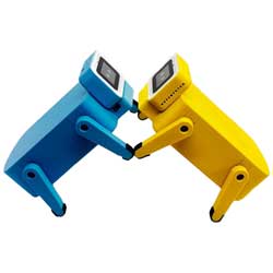
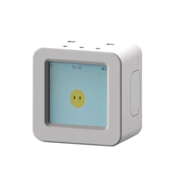
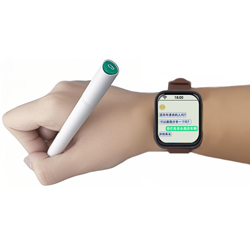
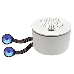
This product is a DualEye display AIoT development board designed for makers and electronics enthusiasts. Based on the ESP32-S3, this microcontroller development board supports 2.4GHz WiFi and Bluetooth LE 5. It integrates large-capacity Flash memory, PSRAM, and dual 1.28-inch LCD screens, allowing for smooth operation of GUI programs such as LVGL. It also features an integrated microphone, speaker, and lithium battery charging circuit, along with a reserved SD card slot and DIY expansion ports. This allows for rapid development of ESP32-S3-based applications such as human-machine interfaces (HMIs),DualEye robotic agents, and AI voice-activated toys. Whether you're looking to create a blinking robot, develop an intelligent IoT interface, enable touch-controlled gaming, or create a futuristic wearable device, this board is an excellent choice.
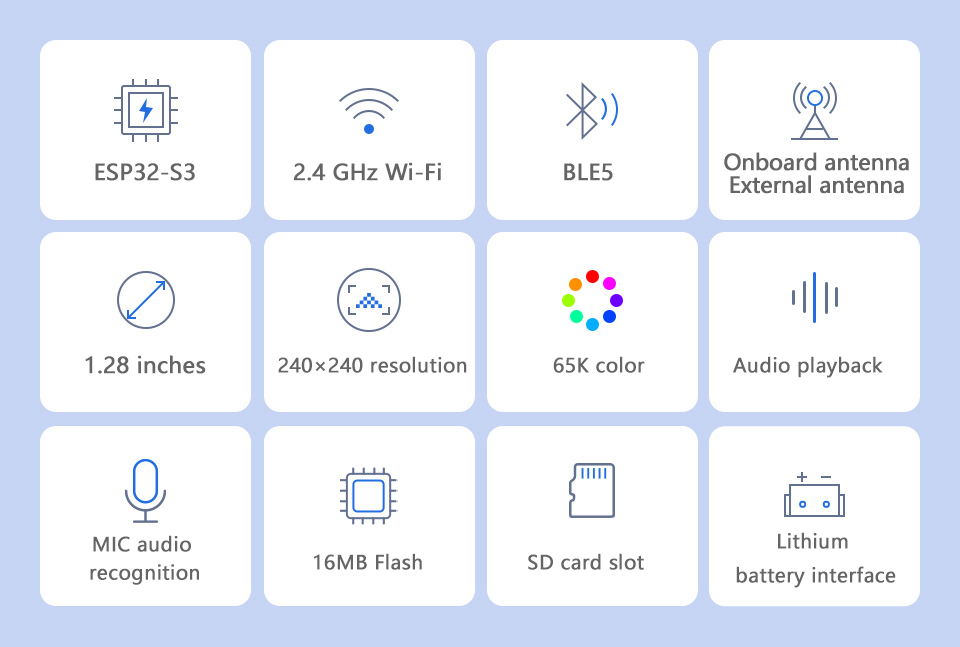
- Equipped with high-performance Xtensa 32-bit LX7 dual-core processor, with a main frequency of up to 240MHz
- Supports 2.4 GHz Wi-Fi (802.11 b/g/n) and Bluetooth 5 (LE) with onboard antenna
- Onboard 512KB SRAM, 384KB ROM, 8MB PSRAM and 16MB Flash
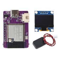
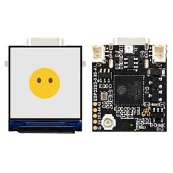
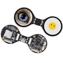
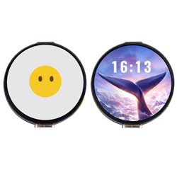
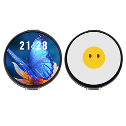
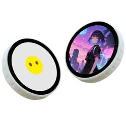
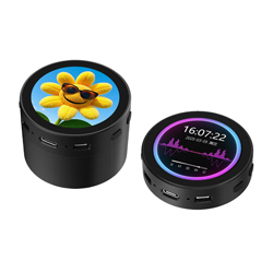
- Two 1.28-inch LCD screens onboard, 240 × 240 resolution, 65K colors, touch screen version optional
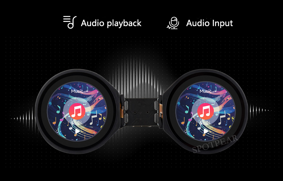
- Onboard ES8311 audio codec and ES7210 audio ADC chips, and equipped with standard microphone and speaker interfaces, supporting AI voice interaction
- Onboard Micro SD card slot for easy expansion of local storage space, supporting storage and reading of data, images, and audio files, etc.
- Onboard lithium battery charging management module, reserved 3.7V lithium battery power supply interface
- Onboard SH1.0 14-pin interface, leading to UART, I2C and some IO interfaces, convenient for DIY custom functions
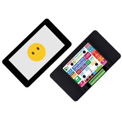
Version selection
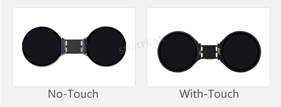 Capacitive touch
Just touch, what you see is what you get, flexible operation and smooth UI interaction
Through I2C signal, touch function is brought out and interrupt is supported
Only the touch version supports touch function
Onboard audio codec chip
Supports high-quality audio processing, providing clear, high-quality audio input and output
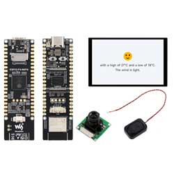
Support AI voice interaction
Supports Xiaozhi AI and can access online large model platforms such as Doubao, DeepSeek and other AI models
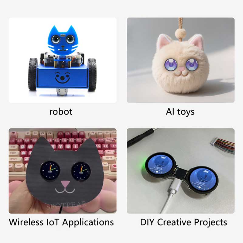
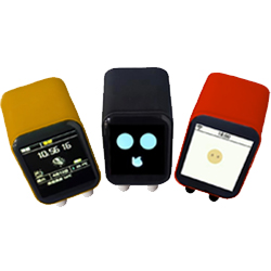
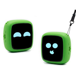
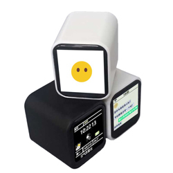
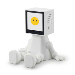
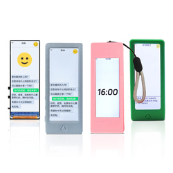
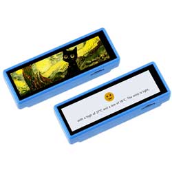
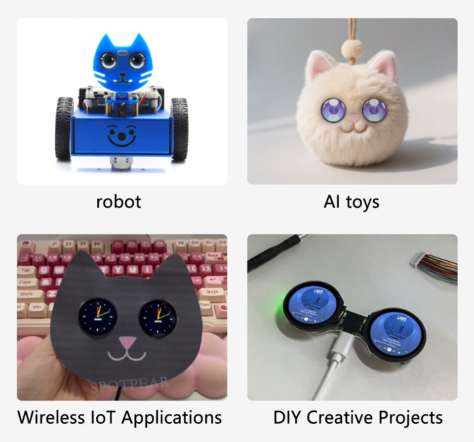
Application Scenario
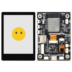
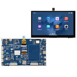
Resource Introduction
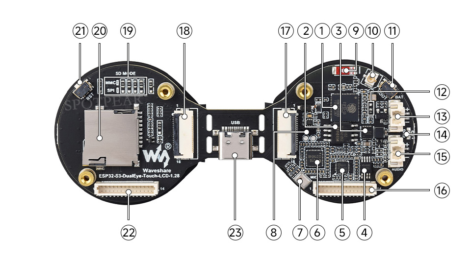
- ESP32-S3R8
Dual-core processor, running at up to 240MHz
- 16MB Flash
- Battery charging management chip
- power amplifier chip
- ES8311
- ES7210
- mike
- MP1605GTF-Z
Power module, supports up to 3.3V 2A output
- Chip ceramic antenna
- IPEX 1st generation transposon
Can be switched to use an external antenna by unsoldering a resistor
- BOOT button
- GPIO1 function modification resistor position
By default, the soldering position is close to the crystal oscillator. In this case, GPIO1 is used for battery voltage measurement. If it is changed to be away from the crystal oscillator, it will be connected to the FPC cable. In this case, the program can be modified to achieve triple-screen display.
- System battery interface
MX1.25 2PIN connector, can be used to connect to 3.7V lithium battery, supports charging and discharging
- Charging indicator light
When connected to the system battery, the charging state is always on and turns off when fully charged (the state is uncertain when not connected to the system battery)
- Speaker jack
- SH1.0 14-pin cable interface
- 18-pin FPC interface
While the motherboard remains powered on, adjust the value of resistor R12 and modify the display configuration parameters in the program to achieve triple-screen display. If the motherboard is broken, you can connect the two screens via the FPC cable to ensure normal operation of both screens (note that the RESET button will be unavailable when the motherboard is broken and the FPC cable is used to connect the two screens).
- 18-pin FPC interface
For connecting to the master
- SD card communication mode selection
When the board is broken, you can switch to SPI mode when using other main controllers to control the SD card side. At this time, you can use a set of SPI to control the SD card and the screen at the same time.
- Micro SD card holder
Allows connection of large capacity SD cards
- RESET button
- SH1.0 14-pin cable interface
When the board is broken, configure the resistor R19 to SPI mode. You can then use a 14-pin cable to control the SD card and screen simultaneously through a set of SPI.
- Type-C port
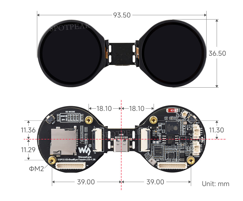
Product size