- sales/support
Google Chat:---
- sales
+86-0755-88291180
- sales01
sales@spotpear.com
- sales02
dragon_manager@163.com
- support
tech-support@spotpear.com
- CEO-Complaints
zhoujie@spotpear.com
- Only Tech-Support
WhatsApp:13246739196
- Purchase/Shipping/Refund
WhatsApp:13424403025
Raspberry Pi CM4-DUAL-ETH-WIFI6-BASE User Guide
Introduction
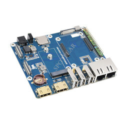
CM4-DUAL-ETH-WIFI6-BASE, the IO board of the Raspberry Pi Compute Module 4, is a carrier board that can be used with the Raspberry Pi Compute Module 4 and supports 7~12V DC power supply, and the board has three USB ports 2.0, WIFI6, dual Ethernet ports, suitable for soft routing and other scenarios that require multiple Ethernet ports.
Note
1. Do not unplug any device except USB and HDMI when the power is on.
2. Check the fan voltage before connecting. It supports 5V and 12V. The default connection is 12V. Before switching, please modify the resistance of FAN_VCC.
3. The Type C interface is only used as a USB SLAVE interface to burn images, and cannot be used as a power supply.
4. When CM4 is in normal use, it needs to provide at least a 12V 1.5A power supply. Otherwise, problems such as automatic shutdown and frequency reduction may occur.
5. See instructions for use about Opwenwrt.
6. This expansion board does not support the POE function.
Dimensions
CM4-DUAL-ETH-WIFI6-BASE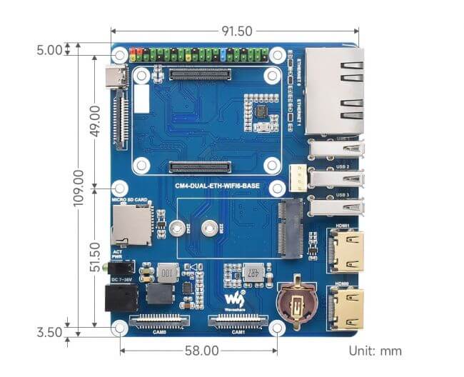
Compute_Module 4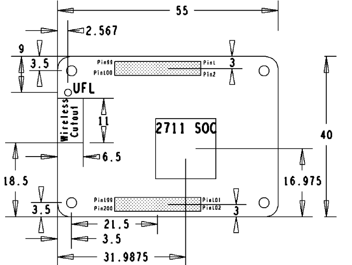
Onboard Resources
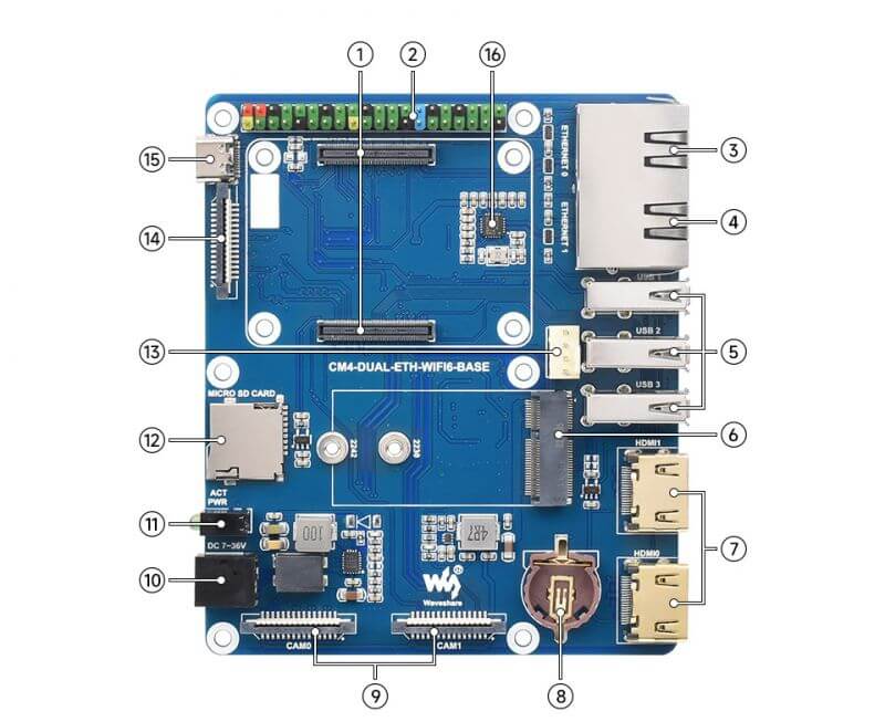
| Label | Name | Description | |
| 1 | CM4 connector | for all versions of Compute Module 4 | |
| 2 | 40PIN GPIO header | easy to connect various HAT modules | |
| 3 | RJ45 Gigabit Ethernet port | RJ45 Gigabit Ethernet port, support 10/100/1000M network access ETHERNET 0: CM4 original network port ETHERNET 1: USB expansion network port | |
| 4 | RJ45 100M Ethernet port | RJ45 100M Ethernet port, support 10/100 network access ETHERNET 0: CM4 original network port ETHERNET 1: USB expansion network port | |
| 5 | USB 2.0 ports | 3-way USB 2.0 ports, supporting various USB devices | |
| 6 | M.2 connector | M.2 E KEY slot, support 2230 and 2240 | |
| 7 | HDMI port | Dual HDMI port, support dual 4K 30fps output | |
| 8 | RTC battery connector | can be connected to CR1220 button battery | |
| 9 | CAM port | Dual MIPI CSI camera port | |
| 10 | DC power header | 7~36V DC wide voltage power supply | |
| 11 | Double LEDs holder | Red light: Raspberry Pi power indicator Green light: Raspberry Pi working status indicator | |
| 12 | Micro SD card slot | It is used to insert the Micro SD card with the system to start Compute Module 4 Lite | |
| 13 | FAN header | Easy access to the cooling fan, support speed adjustment and measurement | |
| 14 | DISP1 port | MIPI DSI display port, DISP1 port | |
| 15 | USB SLAVE port | Compute Module 4 eMMC version can program the system image by this port | |
| 16 | 100M Ethernet port chip | RTL8152 100M network port chip |
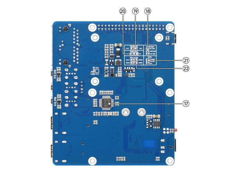
| Label | Name | Description | |
| 17 | USB HUB | USB 2.0 HUB chip | |
| 18 | System function switching | BT_DIS: Disable Bluetooth, only for CM4 version with antenna WiFi_DIS: Disable WiFi, only for CM4 version with antenna WP_DIS: Prevent EEPROM from being rewritten | |
| 19 | IO-VREF selection | CM4 IO logic voltage switching 3.3V or 1.8V | |
| 20 | FAN Power Supply Selection | Optional 5V or 12V voltage to drive the fan | |
| 21 | RTC interrupt pin switch | PI-RUN: RTC trigger interrupt CM4 restart GN-EN: RTC trigger interrupt CM4 power off D4: RTC trigger interrupt D4 pin | |
| 22 | RTC/FAN I2C bus selection | SDA0/SCL0: shared by I2C-10 and CSI/DSI GPIO3/2: shared by I2C-1 and 40PIN |
User Guide
Note
Do not plug or unplug any device while it is powered on.
Image Programming
- Write Image for Compute Module Boards eMMC version
- Write Image for Compute Module Boards Lite version
RTC FAN
Fan
As shown in the figure, switch the FAN voltage according to the position of the resistor, and the default is 12V.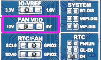
The fan PWM pin is controlled by GPIO18.
RTC
RTC chip: PCF85063A
Default I2C: I2C1
I2C address: 0x51
sudo nano /boot/config.txt
  #Add at the end
  dtparam=i2c_vc=on
  dtoverlay=i2c-rtc,pcf85063a
  #Add # in front of dtparam=audio=on
  #dtparam=audio=on
  #Save and exit, restart
  sudo reboot
Hwclock
Synchronize system clock -> hardware clock.
sudo hwclock -w
Synchronize hardware clock -> system clock.
sudo hwclock -s
  #Need to close the network, or close the network time, otherwise it will be changed back.
Set the hardware clock time:
sudo hwclock --set --date="9/8/2021 16:45:05"View hardware clock.
sudo hwclock -r
Show version information.
sudo hwclock --verbose
CSI DSI
Configure File
CSI and DSI are disabled by default. When using the camera and DSI, three I2C devices, I2C-10, I2C-11, and I2C-0, will be occupied.
Booting is performed as follows:
wget https://www.waveshare.com/w/upload/7/75/CM4_dt_blob_Source.zip
  unzip -o CM4_dt_blob_Source.zip -d ./CM4_dt_blob_Source
  sudo chmod 777 -R CM4_dt_blob_Source
  cd CM4_dt_blob_Source/
  #Execute if two cameras and DSI0 are used
  sudo dtc -I dts -O dtb -o /boot/dt-blob.bin dt-blob-disp0-double_cam.dts
  #Execute if using two cameras and DSI1
  sudo dtc -I dts -O dtb -o /boot/dt-blob.bin dt-blob-disp1-double_cam.dts
  #When using any DSI, HDMI1 has no image output, even if you are not connected to the DSI screen, as long as you compile the corresponding file, then HDMI1 will have no output
  #If you need to restore, delete the corresponding dt-blob.bin: sudo rm -rf /boot/dt-blob.bin
  #Execution is complete, turn off the power and restart CM4
Record Test
Then connect the camera and DSI screen:
1: Make sure to connect when powering off.
2: Connect the power supply.
3: Wait a few seconds for the screen to boot.
4: If it cannot be started, check whether /boot/dt-blob.bin exists and if it exists, restart it again.
Old Version (Buster)
The camera needs to run raspi-config, choose Interfacing Options->Camera->Yes->Finish-Yes, and reboot the system. Open enable camera and restart it to save the changes.
Test the Raspberry Pi camera.
View the screen of the first camera connected:
sudo raspivid -t 0 -cs 0
View the screen of the second connected camera:
sudo raspivid -t 0 -cs 1
New Version (Bullseye)
If you use the newest system OS (Bullseye):
#The new system uses dual cameras
#Remove camera_auto_detect=1 in config.txt
#camera_auto_detect=1

#Add to
dtoverlay=imx219,cam1
dtoverlay=imx219,cam0

#Where imx219 is the camera sensor model, and other sensors are supported
dtoverlay=ov5647,cam0
dtoverlay=imx219,cam0
dtoverlay=ov9281,cam0
dtoverlay=imx477,cam0
dtoverlay=imx519,cam0

# then reboot
reboot

# open camera
libcamera-hello -t 0
or
libcamera-hello


# Other parts of the instructions:
#Check if the camera is detected
libcamera-hello --list-cameras

#Open the corresponding camera, preview for 5 seconds
libcamera-hello --camera 1
libcamera-hello --camera 0

#taking photos
libcamera-jpeg -o test.jpg

#shoot video
libcamera-vid -t 10000 -o test.h264

#You can add --camera to specify the camera
#-t <duration> option allows the user to choose how long the window is displayed in milliseconds
Click here for more commands.
- NOTE: If using a DSI port to display there will be an HDMI disabled, even if just compiling the corresponding file without connecting the DSI screen.
- Any connection between two HDMIs can output images, not limited to that HDMI. If two HDMI screens are connected, only HDMI0 has an image output.
- If you want to enable both HDMI, delete the dt-blob.bin file with the following command:
sudo rm -rf /boot/dt-blob.bin
- Then reboot.
Please refer to Raspberry Pi manual
Openwrt
Openwrt has high customization and scalable performance. Openwrt is becoming more and more popular at present. Compared with commonly used wireless routers, OpenWrt's modifiable firmware allows us to customize router functions according to our own needs, such as single-arm routing, automatic Define routing policies, QoS, intranet penetration, etc.
Note: Openwrt system will not provide any technical support if there is any problem during use. Only the following tutorials and images are provided, and no additional technical support other than hardware is provided.
Image
If the board used does not have USB3.0, only USB 2.0, and the USB2.0 cannot work, try adding "otg_mode=1" at the end of config.txt.
Compiled without configuration
Link: https://drive.google.com/file/d/1KccdLCYQ88Pcm0pp77e3k50qTOSgi_nK/view?usp=share_link
Configured
Link: https://drive.google.com/file/d/17THOPlBPD-BZZJS9_1JpFUj3MW7_fBh0/view?usp=share_link
Openwrt Configuration
The OpenWrt image configured above supports CM4 onboard Wifi and the driver of RTL8153. You can make CM4 into a smart router. Here is a tutorial on how to install Openwrt on the Raspberry Pi to realize the wireless router function, so that the devices in the LAN can access the Internet through the wireless router, and realize the intelligent management of the LAN. The overall network topology is shown below.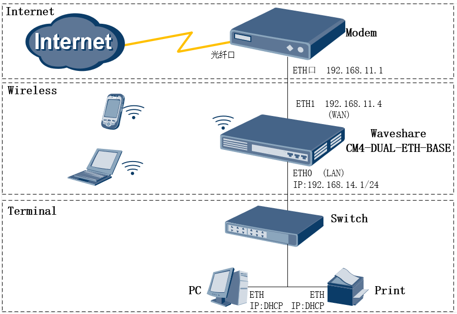
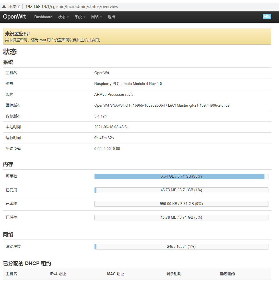
After booting up correctly, log in to the system:
The computer is connected to the ETH0 port, and then directly ssh remote login or web page login.
The configured system default IP is: 192.168.14.1
The default IP of the system without configuration is: 192.168.1.1
Account: root without password.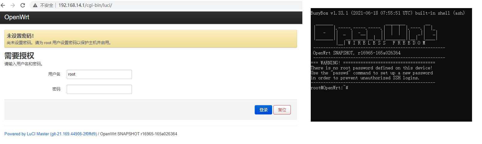
CM4_Openwrt
Raspberry Pi OpenWrt Tutorial 1: System Compilation and Configuration
Raspberry Pi OpenWrt Tutorial 2: Build a Portable Raspberry Pi 4G Wireless Router
If you think the network port is not enough, you can buy USB 3.2 Gen1 TO Gigabit ETH RTL8153 expansion network port, if any ETH/USB HUB HAT RTL8152 can also expand the 100M Ethernet port and support it.