- sales/support
Google Chat:---
- sales
+86-0755-88291180
- sales01
sales@spotpear.com
- sales02
dragon_manager@163.com
- support
tech-support@spotpear.com
- CEO-Complaints
zhoujie@spotpear.com
- Only Tech-Support
WhatsApp:13246739196
- Purchase/Shipping/Refund
WhatsApp:13424403025
- HOME
- >
- PRODUCTS
- >
- Common Module
- >
- Converter
- >
- UART
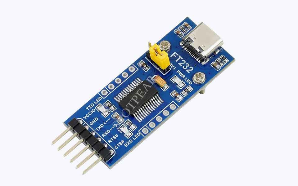
FT232 USB UART Board (Type C) USB To UART (TTL) Communication Module USB C Connector
$3.89
Brand:Spotpear
SKU:0203036
Date:2021-09-01 13:34
Part Number:
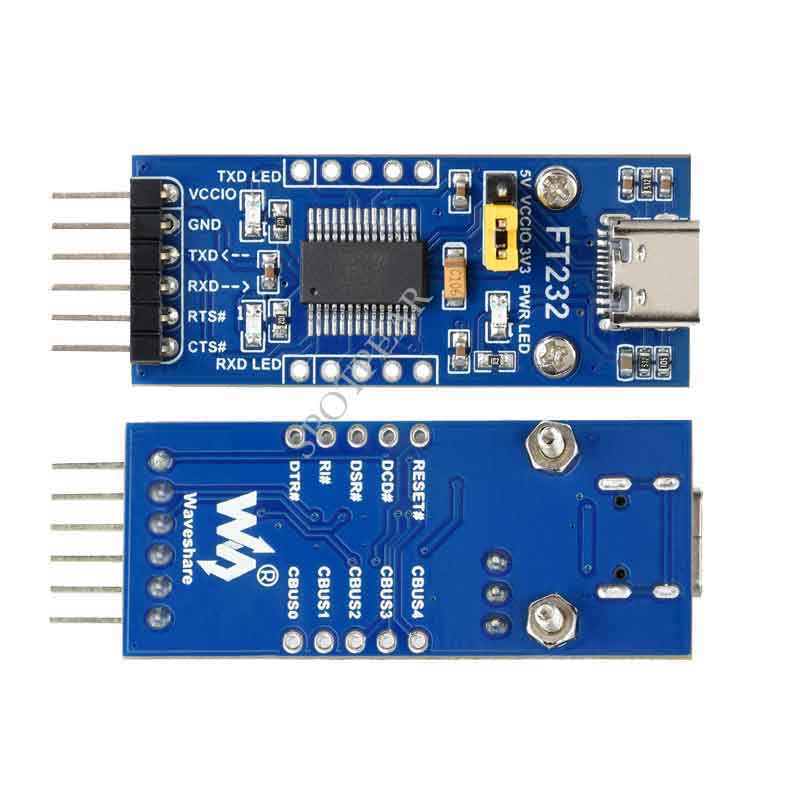
FT232 USB UART Board (Type C) USB To UART (TTL) Communication Module USB-C Connector
Features At A Glance
- Original FT232RL onboard
- Supports Mac OS, Linux, Android, WinCE, Windows 7/8/8.1/10/11...
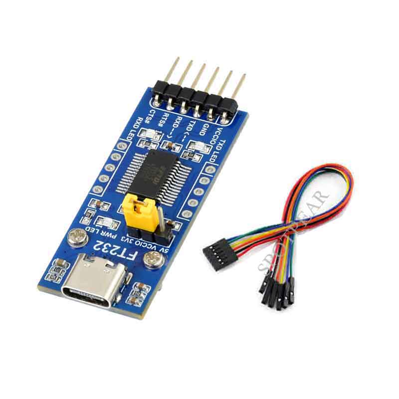
- 3x VCCIO power mode via jumper setting:
- VCCIO - 5V: 5V output
- VCCIO - 3.3V: 3.3V output
- open the jumper: powered from target board (3.3V-5V)
- 3x LED indicators: TXD, RXD, PWR
- Pins accessible on pinheaders: TXD, RXD, RTS#, CTS#
- Other pins are accessible on drilled holes, easily connected to user application system (the pin pitch is compatible with universal prototype board)
FT232 Solution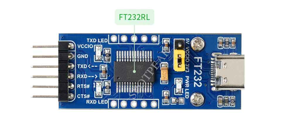
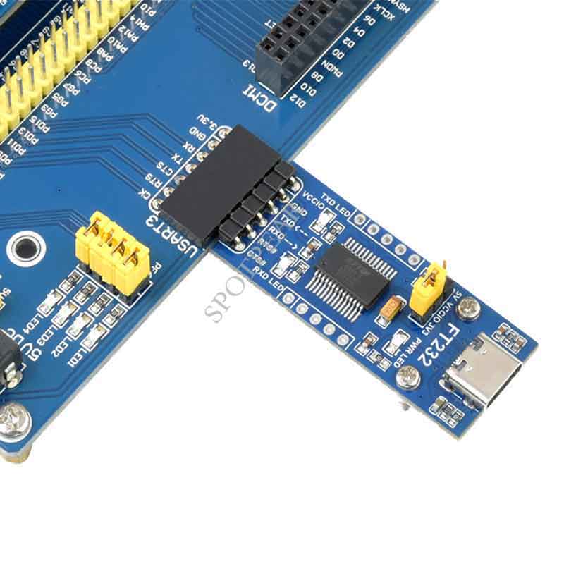
Hardware Connection
In The Case Of Working With MCU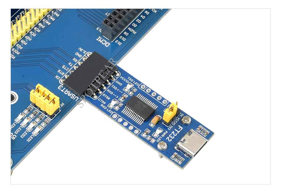
- VCCIO ↔ 3.3V or 5V output (the module is powered from USB, and the onboard jumper should be shorted to 3.3V or 5V)
- GND ↔ GND
- TXD ↔ MCU.RX (signal direction: MCU.RX << FT232 << PC.TX)
- RXD ↔ MCU.TX (signal direction: MCU.TX >> FT232 >> PC.RX)
- RTS ↔ MCU.CTS (signal direction: MCU.CTS << FT232 << PC.RTS)
- CTS ↔ MCU.RTS (signal direction: MCU.RTS >> FT232 >> PC.CTS)
CAUTION: the module is compatible with TTL level ONLY, to avoiding any damage, please DON'T direct connect it to RS232 circuit.
Outline Dimensions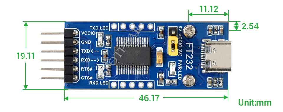
TAG:
Raspberry Pi 5 DSI Cable
Raspberry Pi 5 POE PD Trigger Activation Type C Power Over Ethernet 802.3af/at Pi5
Raspberry Pi 5 Ethernet Moudle
ESP32 C3 Mini
spotpear
Raspberry Pi 8inch LCD 768x1024 Capacitive TouchScreen HDMI Display
Luckfox Lyra Plus RK3506G2
Raspber Pi 5
Raspberry Pi Pico Camera
DeepSeek AI Voice Chat ESP32 S3 1.85 inch Round LCD Display
GPU Monitor Screen
Raspberry Pi 500+ plus Personal computer Mechanical Keyboard With official SSD and Programmable RGB
ESP32-S3 0.85inch LCD
Industrial 4-ch RS485 DC Detection Module Modbus RTU DIN Rail
CM5 Cooling Fan 5V 3007 Raspberry Pi Compute Module 5
Raspberry Pi CM4
Raspberry Pi 5
High Precision 360°Metal Servo Motor 120KG.CM 24V RS485 Closed-Loop Feedback Real-Time Protection
Raspberry Pi 5 PCIe to M.2 SSD
GC9107
Forum: