


- sales/support
Google Chat:---
- sales
+86-0755-88291180
- sales01
sales@spotpear.com
- sales02
dragon_manager@163.com
- support
tech-support@spotpear.com
- CEO-Complaints
zhoujie@spotpear.com
- Only Tech-Support
WhatsApp:13246739196
- Purchase/Shipping/Refund
WhatsApp:13424403025
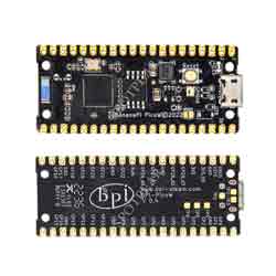
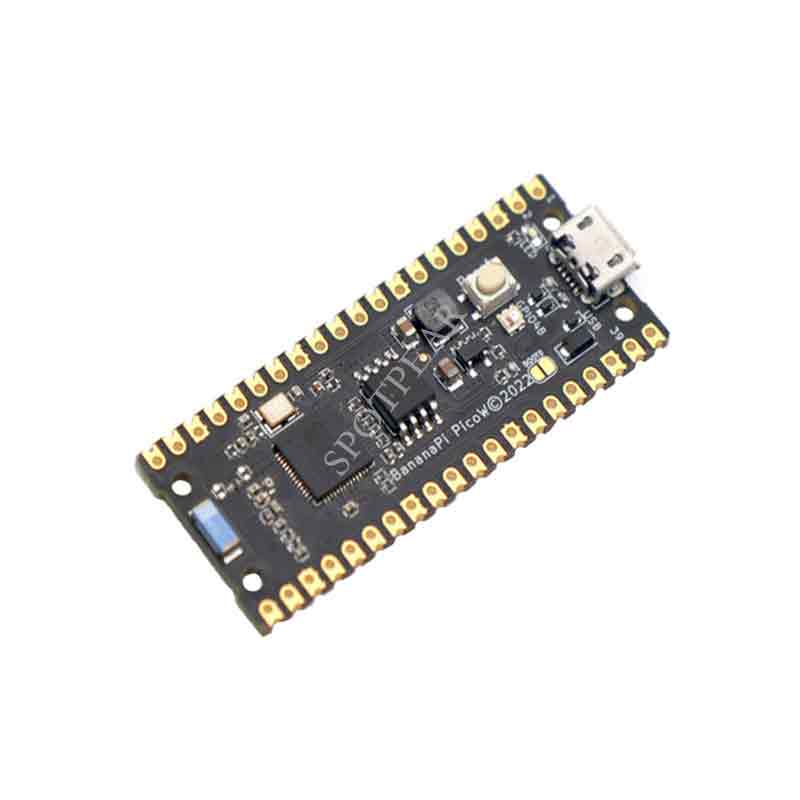
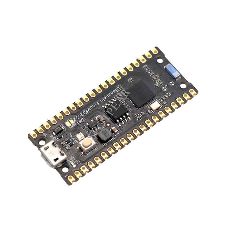
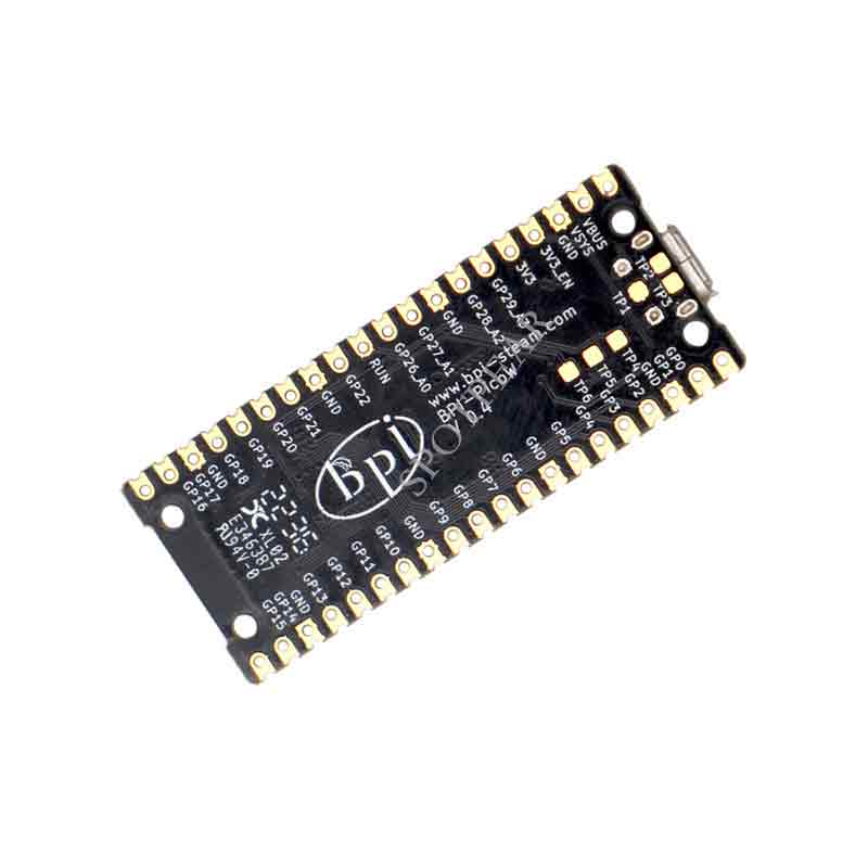
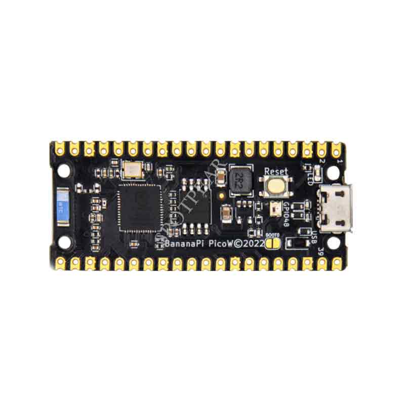
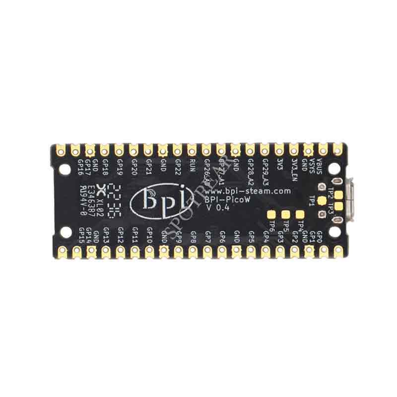
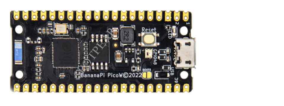
Banana PI BPI PicoW S3 ESP32 S3 BPI Pico W S3 WIFI development board
$6.5
Banana PI BPI-PicoW-S3 ESP32-S3 BPI Pico W S3 WIFI development board
Note
- This is Not a Raspberry Pi Pico W , It is Size Compatible with Raspberry Pi PICO W,
- It have different CPU from Raspberry Pi PICO W
- Which mean you can not run Raspberry Pi official IDE
- However,The Banana Pi give other IDE like ESP-IDF , MicroPython , Arduino IED
Overview
- The Banana Pi BPI-PicoW-S3 is a series of
- low-powered microcontrollers designed for IoT development.
- same size as Raspberry Pi Pico board,It
- supports2.4 GHz Wi-Fi and Bluetooth® LE dual-mode wireless communication,
- the peripheral is compatible with low-power hardware design,
- and the power consumption is only 10uA in deep sleep mode.
- In terms of programming, the PicoW-S3 supports ESP-IDF,
- Arduino, micropython and other methods.
Features
- ESP32-S3, Xtensa® 32 bit LX7
- External PSRAM, FLASH
- Ultra-low power 10uA
- 2.4G WIFI, Bluetooth 5, Bluetooth mesh
- GPIO, ADC, TOUCH, PWM, I2C, SPI, RMT, I2S, UART, LCD, CAMERA, USB, JTAG
- 1 * microUSB
- 1 * Full color LED
BPI-PicoW-S3 VS Raspberry Pi PicoW, BPI-Leaf-S3, ESP32-S3-DevKitC-1
| Development board | BPI-PicoW-S3 | Rraspberry Pi PicoW | BPI-Leaf-S3 | ESP32-S3-DevKitC-1 |
|---|---|---|---|---|
| GPIO pinout | 27 | 27 | 36 | 36 |
| 3.3v pin | 1 | 1 | 2 | 2 |
| 5v pin | 2 | 2 | 1 | 1 |
| GND pin | 8 | 8 | 4 | 4 |
| Full color LED | 1 on GPIO48 | None | 1 on GPIO48 | 1 on GPIO48 |
| Chip directly connected to USB | MicroUSB port x1 | MicroUSB port x1 | Type-C USB port x1 | MicroUSB port x1 |
| UART TTL to USB | None | None | None | CP2102-MicroUSB interface x1 |
| External battery socket | None | None | 3.7v lithium battery power supply interface | None |
| Battery charging | None | None | 500mA charging | None |
| I²C 4pin connector | None | None | 1 | None |
Espressif ESP32-S3
Esp32-S3 is an MCU chip that integrates 2.4 GHz Wi-Fi and Bluetooth 5 (LE) and supports Long Range mode. The ESP32-S3 runs on an Xtensa® 32-bit LX7 dual-core processor with a high frequency of 240 MHz, 512 KB built-in SRAM (TCM), 45 programmable GPIO pins, and a rich communication interface. Esp32-s3 supports larger capacity of high-speed Octal SPI flash and off-chip RAM, and supports user-configured data caching and instruction caching.
What follows is a description of the most important features of ESP32-S3.
- Wi-Fi + Bluetooth 5 (LE) Wireless Connectivity: ESP32-S3 supports a 2.4 GHz Wi-Fi (802.11 b/g/n) with 40 MHz of bandwidth support. The Bluetooth Low Energy subsystem supports long range through Coded PHY and advertisement extension. It also supports higher transmission speed and data throughput, with 2 Mbps PHY. Both Wi-Fi and BLE have superior RF performance that is maintained even at high temperatures.
- AI Acceleration Support: ESP32-S3 has additional support for vector instructions in the MCU, which provides acceleration for neural network computing and signal processing workloads. The software libraries for the above-mentioned optimized functions will become available very soon, in the form of updates to ESP-DSP and ESP-NN.
- Rich IO interfaces: ESP32-S3 has 45 programmable GPIOs and common peripheral interfaces such as SPI, I2S, I2C, PWM, RMT, ADC, UART, SD/MMC host controller and TWAITM controller. Fourteen of the GPIOs can be configured as capacitive touch inputs for HMI interaction. In addition, ESP32-S3 is equipped with an ultra-low power coprocessor (ULP) and supports multiple low-power modes, making it widely applicable to various low-power application scenarios.
- Security mechanism: ESP32-S3 provides comprehensive security mechanism and protection measures for iot devices to prevent all kinds of malicious attacks and threats. It supports Flash encryption based on AES-XTS algorithm, secure startup based on RSA algorithm, digital signature and HMAC. Esp32-s3 also includes a new "World Controller" module, which provides two non-interfering execution environments to implement a trusted execution environment or permission separation mechanism.
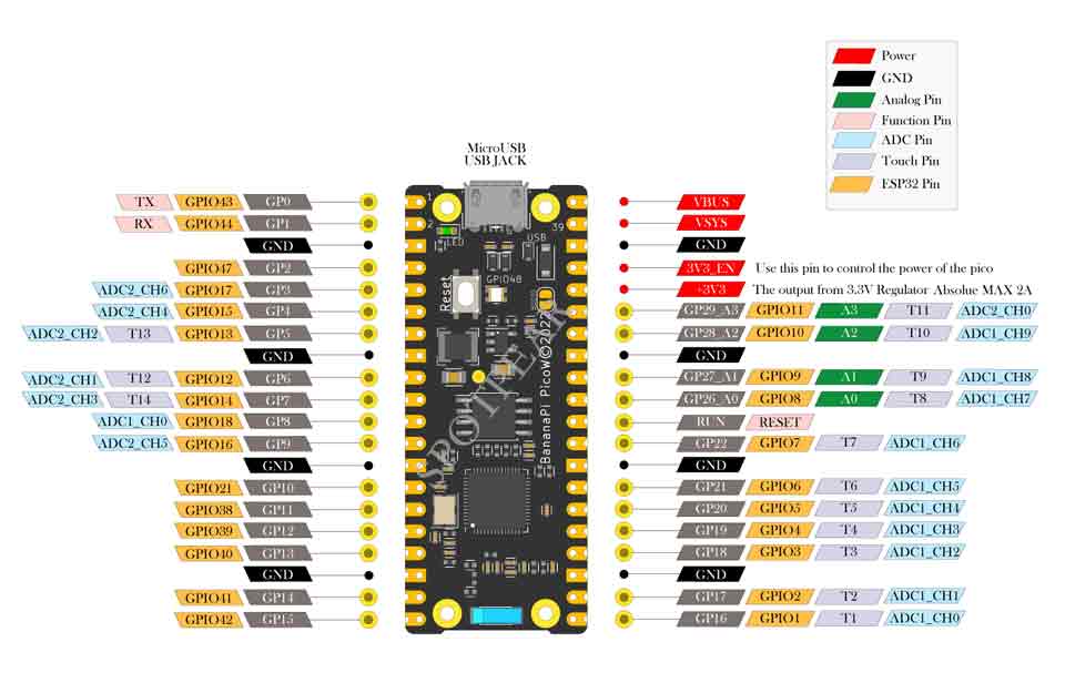
Hardware interface
Hardware spec
| BPI-PicoW-S3 Spec Sheet | |
|---|---|
| SoC | ESP32-S3, Xtensa® 32-bit LX7 dual core |
| Basic frequency | 240MHz MAX |
| Operating temperature | -40℃~+85℃ |
| On-chip ROM | 384KB |
| On-chip SRAM | 320KB |
| Extereal FLASH | 8MB |
| In-packge PSRAM | 2MB |
| WIFI | IEEE 802.11 b/g/n, 2.4Ghz band, 150Mbps |
| Bluetooth | Bluetooth 5, Bluetooth mesh |
| GPIO | BPI-PicoW-S3 has led out 27 available GPIOs |
| ADC | 2 × 12-bit SAR ADC supporting 18 analog channel inputs |
| TOUCH Capacitive Touch Sensor | 14 |
| SPI | 4 |
| I2C | 2. Support master or slave mode |
| I2S | 2, input and output of serial stereo data |
| LCD | 1, support 8-bit ~16-bit parallel RGB, I8080, MOTO6800 interface |
| CAMERA | 1, supports 8-bit ~16-bit DVP image sensor interface |
| UART | 3, supports asynchronous communication (RS232 and RS485) and IrDA |
| PWM | 8 independent channels, 14-bit precision |
| MCPWM | 2 |
| USB | 1 × Full Speed USB 2.0 OTG, MicroUSB Female |
| USB Serial/JTAG Controller | 1, USB full speed standard, CDC-ACM, JTAG |
| Temperature sensor | 1, the measurement range is –20 °C to 110 °C, for monitoring the internal temperature of the chip |
| SD/MMC | 1 × SDIO host interface, with 2 card slots, supports SD card 3.0 and 3.01, SDIO 3.0, CE-ATA 1.1, MMC 4.41, eMMC 4.5 and 4.51 |
| TWAI® Controller | 1, compatible with ISO11898-1 (CAN specification 2.0) |
| Generic DMA Controller | 5 receive channels and 5 transmit channels |
| RMT | 4-channel transmit, 4-channel receive, shared 384 x 32-bit RAM |
| Pulse Counter | 4 pulse count controllers (units), each unit has 2 independent channels |
| Timer | 4 × 54-bit general-purpose timers, 16-bit clock prescaler, 1 × 52-bit system timer, 3 × watchdog timers |
| External crystal | 40Mhz |
| RTC and Low Power Management | Power Management Unit (PMU) + Ultra Low Power Coprocessor (ULP) |
| Low power consumption current | 10uA |
| Working Voltage | 3.3V |
| Input voltage | 3.3V~5.5V |
| Maximum discharge current | 2A@3.3V DC/DC |
| Controllable full color LED | 1 |
| Controllable monochrome LED | 1 |
Features
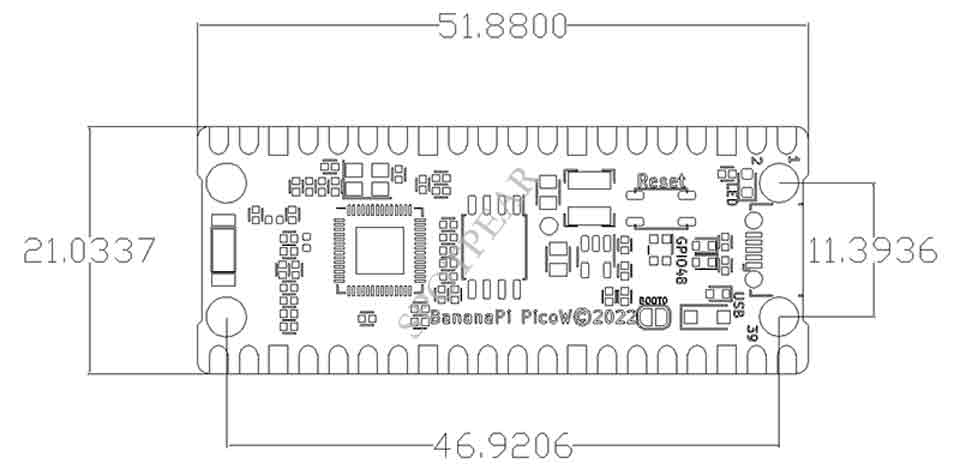
| BPI-PicoW-S3 size chart | |
|---|---|
| Pin spacing | 2.54mm |
| Hole Spacing | 11.4mm/ 47mm |
| Hole size | Inner diameter 2.1mm/Outer diameter 3.4mm |
| Mainboard size | 21 × 51.88(mm)/0.83 x 2.04(inches) |
| Thickness | 1.2mm |
The pin spacing is compatible with universal boards (hole boards, dot matrix boards) and breadboards, which is convenient for debugging applications.
GPIO define
| BPI-PicoW-S3 peripheral GPIO pin assignment | ||
|---|---|---|
| Peripheral Interface | Signal | Pins |
| ADC | ADC1_CH0~9 | GPIO 1~10 |
| ADC2_CH0~9 | GPIO 11~20 | |
| Touch Sensor | TOUCH1~14 | GPIO 1~14 |
| JTAG | MTCK | GPIO 39 |
| MTDO | GPIO 40 | |
| MTDI | GPIO 41 | |
| MTMS | GPIO 42 | |
| UART | Default assigned pins, can be redefined as any GPIO | |
| U0RXD_in | GPIO 44 | |
| U0CTS_in | GPIO 16 | |
| U0DSR_in | Any GPIO | |
| U0TXD_out | GPIO43 | |
| U0RTS_out | GPIO 15 | |
| U0DTR_out | Any GPIO | |
| U1RXD_in | GPIO 18 | |
| U1CTS_in | GPIO 20 | |
| U1DSR_in | Any GPIO | |
| U1TXD_out | GPIO 17 | |
| U1RTS_out | GPIO 19 | |
| U1DTR_out | Any GPIO | |
| U2 | Any GPIO | |
| I2C | Any GPIO | |
| PWM | Any GPIO | |
| I2S | Any GPIO | |
| LCD | Any GPIO | |
| CAMERA | Any GPIO | |
| RMT | Any GPIO | |
| SPI0/1 | Used for FLASH and PSRAM | |
| SPI2/3 | Any GPIO | |
| Pulse Counter | Any GPIO | |
| USB OTG | D- | GPIO 19 (internal PHY) |
| D+ | GPIO 20 (internal PHY) | |
| VP | GPIO 42 (External PHY) | |
| VM | GPIO 41 (External PHY) | |
| RCV | GPIO21 (External PHY) | |
| OEN | GPIO 40 (External PHY) | |
| VPO | GPIO 39 (External PHY) | |
| VMO | GPIO38 (External PHY) | |
| USB Serial/JTAG | D- | GPIO 19 (internal PHY) |
| D+ | GPIO 20 (internal PHY) | |
| VP | GPIO 42 (External PHY) | |
| VM | GPIO 41 (External PHY) | |
| OEN | GPIO 40 (External PHY) | |
| VPO | GPIO 39 (External PHY) | |
| VMO | GPIO38 (External PHY) | |
| SD/MMC | Any GPIO | |
| MCPWM | Any GPIO | |
| TWAI | Any GPIO | |
| Full Color LED | GPIO 48 | |
| Monochrome LED | GPIO 46 | |
