- sales/support
Google Chat:---
- sales
+86-0755-88291180
- sales01
sales@spotpear.com
- sales02
dragon_manager@163.com
- support
tech-support@spotpear.com
- CEO-Complaints
zhoujie@spotpear.com
- Only Tech-Support
WhatsApp:13246739196
- Purchase/Shipping/Refund
WhatsApp:13424403025
- HOME
- >
- ARTICLES
- >
- LuckFox
- >
- Luckfox PICO
GPIO
GPIO
In this chapter, we will learn how to use the sysfs file system to access and control GPIO (General-Purpose Input/Output) pins.
Sample program : Code.zip
1. GPIO Subsystem
GPIO (General-Purpose Input/Output) is a type of universal pin that can be controlled by microcontrollers (MCUs) or CPUs. It has various functions, including detecting high or low-level inputs and controlling outputs. In Linux, GPIO pins can be exported to user space and controlled through the sysfs file system, allowing GPIO pins to be used for various purposes such as serial communication, I2C, network communication, voltage detection, and more.
Linux has a dedicated GPIO subsystem driver framework for handling GPIO devices. Through this framework, users can easily interact with the GPIO pins of the CPU. This driver framework supports using pins for basic input and output functions, and input functions also support interrupt detection. This allows developers to easily use GPIO pins for various purposes, providing flexibility and programmability. More detailed information about the GPIO subsystem can be found in the <Linux Kernel Source>/Documentation/gpio directory.
2. GPIO Control (Shell)
2.1 Pin Distribution
When exporting GPIO pins to user space, pin numbers are typically needed. These pin numbers can be determined using interface diagrams.LuckFox Pico Ultra/Ultra W Diagram: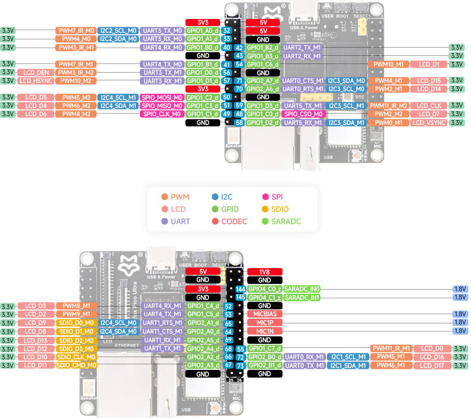
2.2 Calculating Pin Numbers
The pin numbers corresponding to GPIOs are marked in the pinout diagram, and you can use them directly or calculate them as follows:
GPIOs are divided into 5 banks: GPIO0 to GPIO4, with each bank having 4 groups, resulting in a total of 32 pins: A0 to A7, B0 to B7, C0 to C7, D0 to D7.
GPIOs are named in the format GPIO{bank}_{group}{X}, as shown below:
GPIO0_A0 ~ A7
GPIO0_B0 ~ B7
GPIO0_C0 ~ C7
GPIO0_D0 ~ D7

GPIO1_A0 ~ A7
....
GPIO1_D0 ~ D7
....
GPIO4_D0 ~ D7
The GPIO pin number can be calculated using the following formula:
GPIO pin number calculation formula: pin = bank * 32 + number
GPIO group number calculation formula: number = group * 8 + X
Therefore: pin = bank * 32 + (group * 8 + X)
As an example, let's consider GPIO1_C7_d, where:
bank: 1group: 2 (A=0, B=1, C=2, D=3)X: 7
So, the pin number of GPIO1_C7_d is: 1 x 32 + (2 x 8 + 7) = 55
2.3 Device Directory
In the /sys/class/gpio directory, each GPIO device has its own folder. The folder names are gpio followed by the pin number, for example, /sys/class/gpio/gpio55 represents pin number 55, which is GPIO1_C7_d. You can use the following command to check:
# ls /sys/class/gpio/
gpio55   gpiochip96   gpiochip0    gpiochip128  unexport     export       gpiochip32
2.4 Device Attributes
In these device directories, you can also find control files related to GPIO pins, including direction, value, and interrupts, among others. Each GPIO device directory contains a set of attribute files used to configure and manage GPIO pins. You can use the following command in the GPIO device directory:
View the attribute files of GPIO 55 device:
# echo 55 > /sys/class/gpio/export
# cd gpio55
# ls
value       power       subsystem   active_low
uevent      edge        device      direction
Attribute Files
Using these attribute files, you can easily configure and control GPIO pins to adapt to different application scenarios and requirements. Some of the key attributes include:
- Direction (direction):
- Configured as input: in
- Configured as output: out
- Value (value):
- Output low level: 0
- Output high level: 1
- Interrupt edge (edge):
- Rising edge-triggered: rising
- Falling edge-triggered: falling
- Both edge-triggered: both
- Disable interrupts: none
- Direction (direction):
2.5 Controlling GPIO Pin Levels
The device's attribute files serve as an interface for function parameters. For /sys/class/gpio/gpio55/value, each time a write operation is performed on the file, it triggers the driver code to modify the level of GPIO pin 55 using the content written as a parameter. Each time a read operation is performed, it triggers the driver code to update the current level of GPIO pin 55 to the /sys/class/gpio/gpio55/value file.
Export GPIO 55 to user space:echo 55 > /sys/class/gpio/exportRead the level of GPIO1_C7_d:
echo 55 > /sys/class/gpio/export
echo in > /sys/class/gpio/gpio55/direction
cat /sys/class/gpio/gpio55/value
Control the level of GPIO1_C7_d:echo out > /sys/class/gpio/gpio55/direction
echo 1 > /sys/class/gpio/gpio55/value
echo 0 > /sys/class/gpio/gpio55/value
Unexport GPIO 55 from user space:echo 55 > /sys/class/gpio/unexport
3. GPIO Control (Python Program)
In the previous sections, we demonstrated how to use the echo command to modify device files to achieve device control. Next, we will implement GPIO control using a Python program.
3.1 Complete Code
The following program enables the control and reading of GPIO pin levels.
from periphery import GPIO
import time

Write_Pin = 55
Read_Pin = 54

Write_GPIO = GPIO(Write_Pin, "out")
Read_GPIO = GPIO(Read_Pin, "in")

try:
    while True:
        try:
            Write_GPIO.write(True)
            pin_state = Read_GPIO.read()
            print(f"Pin state: {pin_state}")

            Write_GPIO.write(False)
            pin_state = Read_GPIO.read()
            print(f"Pin state: {pin_state}")

            time.sleep(1)

        except KeyboardInterrupt:
            Write_GPIO.write(False)
            break

except IOError:
    print("Error")

finally:
    Write_GPIO.close()
    Read_GPIO.close()
3.2 Configure GPIO Direction
This code segment uses the periphery library to open two GPIO pins in Python. Write_GPIO is used for output, and Read_GPIO is used for input.
Write_GPIO = GPIO(Write_Pin, "out")
Read_GPIO = GPIO(Read_Pin, "in")
3.3 Control Pin Output Level
This code segment uses the Write_GPIO object to write a logic value of True to the GPIO pin to set the pin output to a high level. Writing a logic value of False to the GPIO pin sets the pin output to a low level.
Write_GPIO.write(True)
....
Write_GPIO.write(False)
3.4 Control Pin Read Level
This code reads the state of the Read_GPIO pin and prints it. Read_GPIO.read() returns the level state of the pin (True for high level, False for low level).
pin_state = Read_GPIO.read()
print(f"Pin state: {pin_state}")
3.5 Running the Program
Use the vi tool in the terminal to create a Python file, paste the Python program, and save it.
# nano gpio.pyRun the program.
# python3 gpio.py
4. GPIO Control (C Program)
In the previous sections, we demonstrated how to control GPIO using the echo command and Python programs. Additionally, you can also use the vi editor to modify files, but be cautious about user permissions when making changes. Moreover, we can use C library functions or system calls to read and write device files for device control. Please note that to run programs on specific embedded systems, it's often necessary to use cross-compilation tools to compile the code and generate executable files that can run on the target development board. Let's explore the specific implementation steps together.
4.1 Complete Code
With the following program, you can control the GPIO pin levels.
#include <stdio.h>
#include <stdlib.h>
#include <unistd.h>

int main() {
    int gpio_pin;

    printf("Please enter the GPIO pin number: ");
    scanf("%d", &gpio_pin);

    FILE *export_file = fopen("/sys/class/gpio/export", "w");
    if (export_file == NULL) {
        perror("Failed to open GPIO export file");
        return -1;
    }
    fprintf(export_file, "%d", gpio_pin);
    fclose(export_file);

    char direction_path[50];
    snprintf(direction_path, sizeof(direction_path), "/sys/class/gpio/gpio%d/direction", gpio_pin);
    FILE *direction_file = fopen(direction_path, "w");
    if (direction_file == NULL) {
        perror("Failed to open GPIO direction file");
        return -1;
    }
    fprintf(direction_file, "out");
    fclose(direction_file);

    char value_path[50];
    char cat_command[100];
    snprintf(value_path, sizeof(value_path), "/sys/class/gpio/gpio%d/value", gpio_pin);
    snprintf(cat_command, sizeof(cat_command), "cat %s", value_path);
    FILE *value_file = fopen(value_path, "w");
    if (value_file == NULL) {
        perror("Failed to open GPIO value file");
        return -1;
    }

    for (int i = 0; i < 3; i++) {
        fprintf(value_file, "1");
        fflush(value_file);

        system(cat_command);
        sleep(1);

        fprintf(value_file, "0");
        fflush(value_file);

        system(cat_command);
        sleep(1);
    }

    fclose(value_file);

    FILE *unexport_file = fopen("/sys/class/gpio/unexport", "w");
    if (unexport_file == NULL) {
        perror("Failed to open GPIO unexport file");
        return -1;
    }
    fprintf(unexport_file, "%d", gpio_pin);
    fclose(unexport_file);

    return 0;
}
4.2 Exporting a Pin to User Space
This code reads the user-input pin number, opens the /sys/class/gpio/export file, and writes that number to it, achieving the export operation for a GPIO pin.
printf("Please enter the GPIO pin number: ");
scanf("%d", &gpio_pin);

FILE *export_file = fopen("/sys/class/gpio/export", "w");
if (export_file == NULL) {
    perror("Failed to open GPIO export file");
    return -1;
}
fprintf(export_file, "%d", gpio_pin);
fclose(export_file);
4.3 Configuring GPIO Direction
This code opens the /sys/class/gpio/gpiox/direction file and writes "out" to ensure that the GPIO pin is set to output mode. If you want to configure it as an input, you would write "in" instead.
char direction_path[50];
snprintf(direction_path, sizeof(direction_path), "/sys/class/gpio/gpio%d/direction", gpio_pin);
FILE *direction_file = fopen(direction_path, "w");
if (direction_file == NULL) {
    perror("Failed to open GPIO direction file");
    return -1;
}
fprintf(direction_file, "out");
fclose(direction_file);
4.4 Controlling Pin Output Level
This code is used to control the GPIO pin's logic level. First, you need to open the /sys/class/gpio/gpiox/value file, which is used to set the GPIO pin's logic level. In a loop, we control the pin by sequentially writing "1" and "0" to the file. Then, we use the cat command to check the value stored in the value file to verify if the write was successful.
Note that the standard C library typically uses buffers to improve the efficiency of file operations rather than writing data to disk files immediately after each write. This means that even though you use fprintf to write data, the data may be temporarily held in the buffer and not immediately written to the file. If you want to ensure that data is written to the file immediately, you can use the fflush function to flush the buffer, which forces the data in the buffer to be written to the file, or use the fopen->fprintf->fclose approach for each write.
char value_path[50];
char cat_command[100];
snprintf(value_path, sizeof(value_path), "/sys/class/gpio/gpio%d/value", gpio_pin);
snprintf(cat_command, sizeof(cat_command), "cat %s", value_path);
FILE *value_file = fopen(value_path, "w");
if (value_file == NULL) {
    perror("Failed to open GPIO value file");
    return -1;
}

for (int i = 0; i < 3; i++) {
    fprintf(value_file, "1");
    fflush(value_file);

    system(cat_command);
    sleep(1);

    fprintf(value_file, "0");
    fflush(value_file);

    system(cat_command);
    sleep(1);
}

fclose(value_file);
4.5 Unexporting a Pin
This code opens the /sys/class/gpio/unexport file and writes the GPIO pin's number to it, achieving the unexport operation for a GPIO pin.
FILE *unexport_file = fopen("/sys/class/gpio/unexport", "w");
if (unexport_file == NULL) {
    perror("Failed to open GPIO unexport file");
    return -1;
}
fprintf(unexport_file, "%d", gpio_pin);
fclose(unexport_file);
4.6 Cross-Compilation
Specify the Cross-Compilation Tool
First, you need to add the path to the cross-compilation tool to the system's
PATHenvironment variable so that you can use the cross-compilation tool from anywhere. You can add the following line to your shell configuration file (usually~/.bashrcor~/.bash_profileor~/.zshrc, depending on your shell). Note that the path afterPATH=should point to the directory where the cross-compilation tool is located.gcc path
<SDK Directory>/tools/linux/toolchain/arm-rockchip830-linux-uclibcgnueabihf/bin/arm-rockchip830-linux-uclibcgnueabihf-gccOpen the shell configuration file.
vi ~/.bashrcAdd the path of the cross-compilation tool to the system's PATH environment variable. Replace
<SDK Directory>with your own SDK path, such as/home/luckfox/luckfox-pico/.export PATH=<SDK Directory>/tools/linux/toolchain/arm-rockchip830-linux-uclibcgnueabihf/bin:$PATHReload the shell configuration file to apply the changes:
source ~/.bashrc
Compile the Program Using the Cross-Compilation Tool
arm-rockchip830-linux-uclibcgnueabihf-gcc gpio.c -o gpioAfter successful cross-compilation, an executable file that can run on the development board will be generated in the current directory.
# ls
gpio  gpio.c
4.7 Running the Program
File Transfer
First, transfer the
gpioprogram from the virtual machine to Windows, and then transfer it to the development board via TFTP or ADB. Here are the steps to transfer the file from Windows to the development board using ADB:adb push path_to_file destination_on_development_board
eg: (Transferring the `gpio` file from the current directory to the root directory of the development board)
adb push gpio /Running the Program
Modify the permissions of the
gpiofile and then run the program:# chmod 777 gpio
# ./gpio