


- sales/support
Google Chat:---
- sales
+86-0755-88291180
- sales01
sales@spotpear.com
- sales02
dragon_manager@163.com
- support
tech-support@spotpear.com
- CEO-Complaints
zhoujie@spotpear.com
- Only Tech-Support
WhatsApp:13246739196
- Purchase/Shipping/Refund
WhatsApp:13424403025
Raspberry-Pi-Pico-2-W User Guide
Overview
Introduction
Raspberry Pi Pico 2 W is an official Raspberry Pi-designed, low-cost yet flexible development platform based on the RP2350, which is a wireless upgrade of the Raspberry Pi Pico 2. It features all the characteristics of the Pico2 with the addition of a 2.4GHz wireless interface.
Features
- RP2350 microcontroller chip designed by Raspberry Pi
- Adopts unique dual-core and dual-architecture design, equipped with dual-core ARM Cortex-M33 processor and dual-core Hazard3 RISC-V core processor, flexible clock running up to 150 MHz
- Built-in 520KB of SRAM and 4MB of on-chip Flash
- Supports Wi-Fi 4 wireless network and Bluetooth 5.2
- Castellated module allows soldering directly to carrier boards
- USB1.1 host and device support
- Supports low-power sleep and hibernation modes
- Drag-and-drop downloads can be made by USB recognition as mass storage
- 26 × multi-functional GPIO pins
- 2 × SPI, 2 × I2C, 2 × UART, 3 × 12-bit ADC, 16 × controllable PWM channels
- Temperature sensor
- Accelerated floating-point libraries on-chip
- 12 × Programmable I/O (PIO) state machines for custom peripheral support
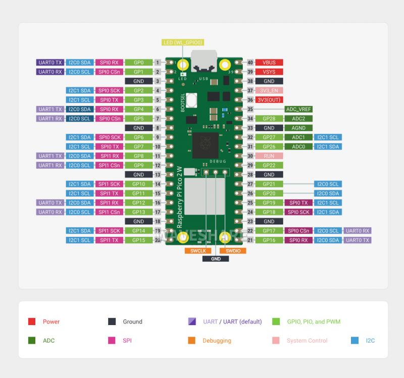
Pinout Definition
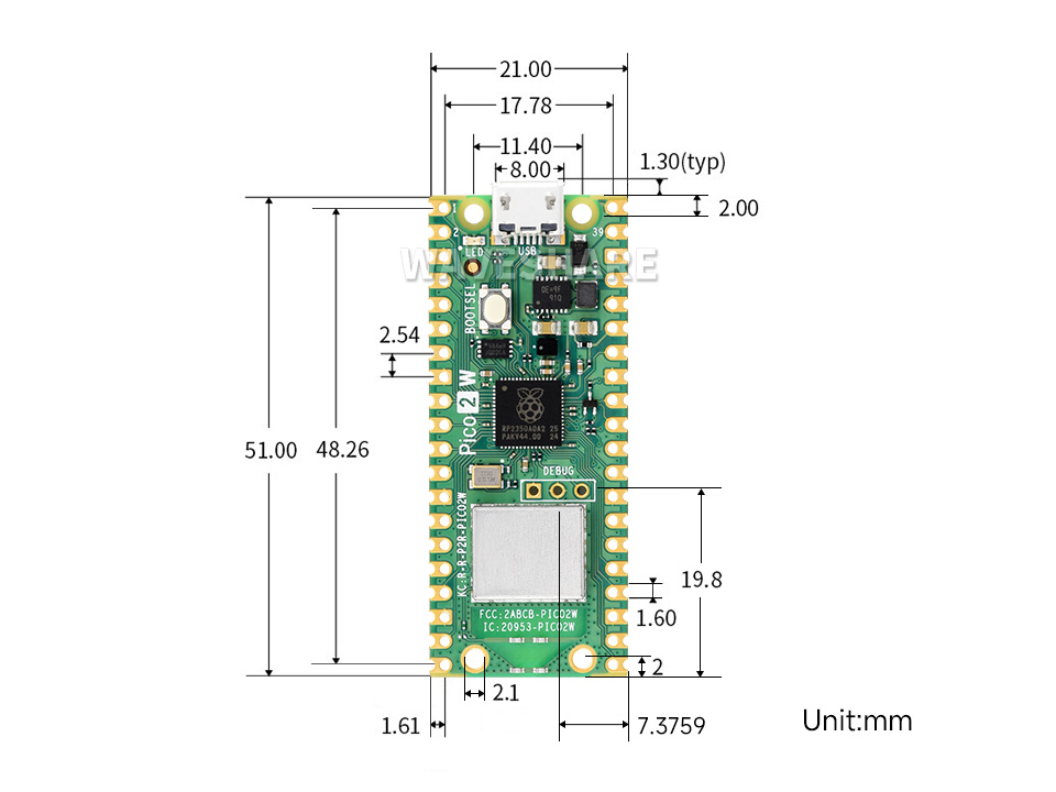
Dimensions
Pico Getting Started
Firmware Download
- MicroPython Firmware Download

- C_Blink Firmware Download

Basic Introduction
MicroPython Series
Install Thonny IDE
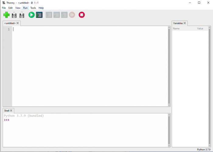
In order to facilitate the development of Pico/Pico2 boards using MicroPython on a computer, it is recommended to download the Thonny IDE
- Download Thonny IDE and follow the steps to install, the installation packages are all Windows versions, please refer to Thonny's official website for other versions
- After installation, the language and motherboard environment need to be configured for the first use. Since we are using Pico/Pico2, pay attention to selecting the Raspberry Pi option for the motherboard environment
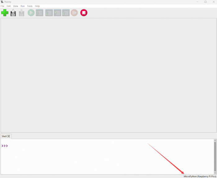
- Configure MicroPython environment and choose Pico/Pico2 port
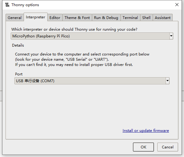
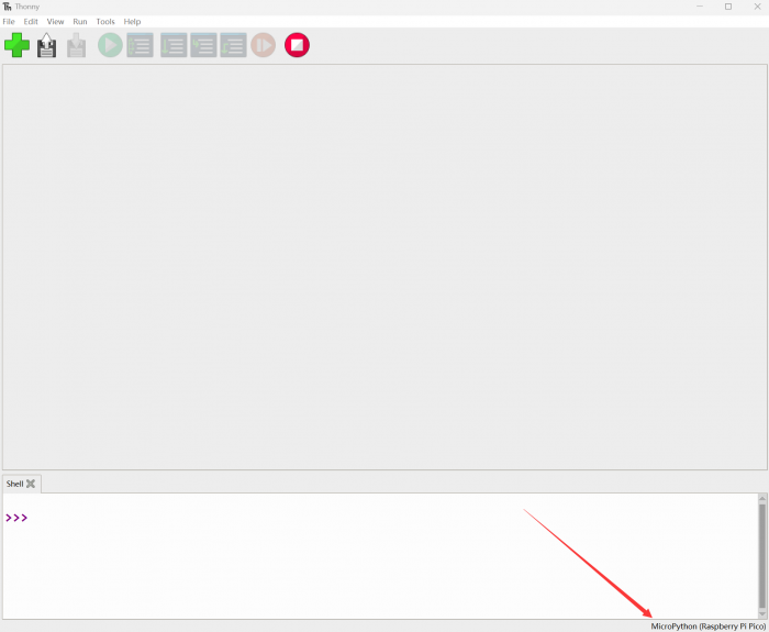
- Connect Pico/Pico2 to your computer first, and in the lower right corner of Thonny left-click on the configuration environment option --> select Configture interpreter
- In the pop-up window, select MicroPython (Raspberry Pi Pico), and choose the corresponding port
Flash Firmware
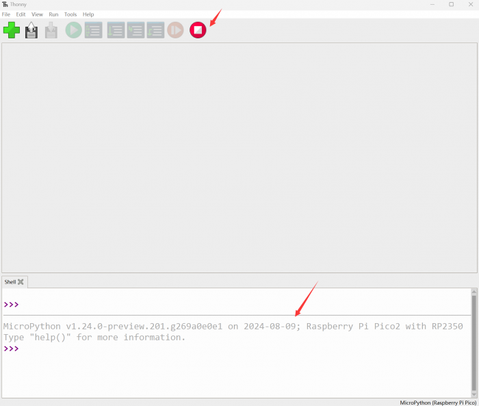
- Click OK to return to the Thonny main interface, download the corresponding firmware library and burn it to the device, and then click the Stop button to display the current environment in the Shell window
- Note: Flashing the Pico2 firmware provided by Micropython may cause the device to be unrecognized, please use the firmware below or in the package
- How to download the firmware library for Pico/Pico2 in windows: After holding down the BOOT button and connecting to the computer, release the BOOT button, a removable disk will appear on the computer, copy the firmware library into it
- How to download the firmware library for RP2040/RP2350 in windows: After connecting to the computer, press the BOOT key and the RESET key at the same time, release the RESET key first and then release the BOOT key, a removable disk will appear on the computer, copy the firmware library into it (you can also use the Pico/Pico2 method)
MicroPython Series Tutorials
【MicroPython】 machine.Pin class function details
【MicroPython】machine.PWM class function details
【MicroPython】machine.ADC class function details
【MicroPython】machine.UART class function details
【MicroPython】machine.I2C class function details
【MicroPython】machine.SPI class function details
【MicroPython】rp2.StateMachine class function details
C/C++ Series
For C/C++, it is recommended to use Pico VSCode for development. This is a Microsoft Visual Studio Code extension designed to make it easier for you to create, develop, and debug projects for the Raspberry Pi Pico series development boards. No matter if you are a beginner or an experienced professional, this tool can assist you in developing Pico with confidence and ease. Here's how to install and use the extension.
- Official website tutorial: https://www.raspberrypi.com/news/pico-vscode-extension/
- This tutorial is suitable for Raspberry Pi Pico, Pico2 and the RP2040 and RP2350 series development boards developed by Waveshare
- The development environment defaults to Windows11. For other environments, please refer to the official tutorial for installation
Install VSCode
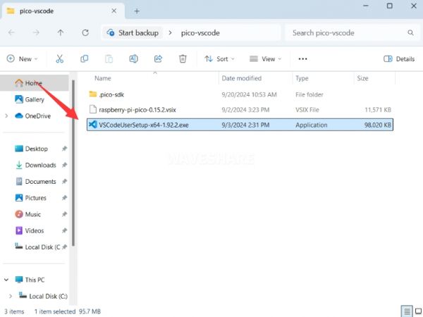
- First, click to download pico-vscode package, unzip and open the package, double-click to install VSCode
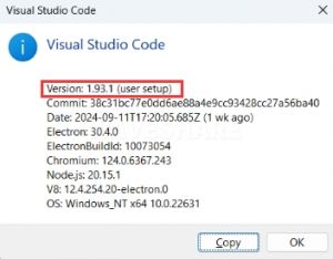
Note: If vscode is installed, check if the version is v1.87.0 or later
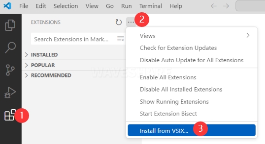
Install Extension
- Click Extensions and select Install from VSIX
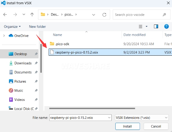
- Select the package with the vsix suffix and click Install
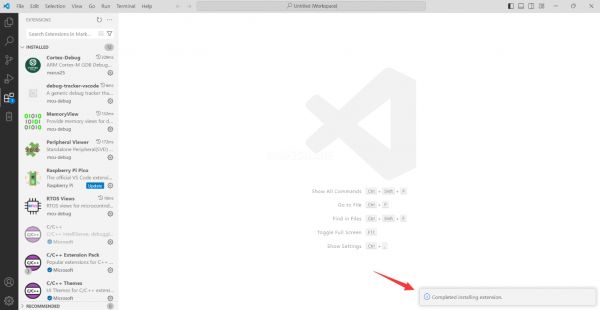
- Then vscode will automatically install raspberry-pi-pico and its dependency extensions, you can click Refresh to check the installation progress
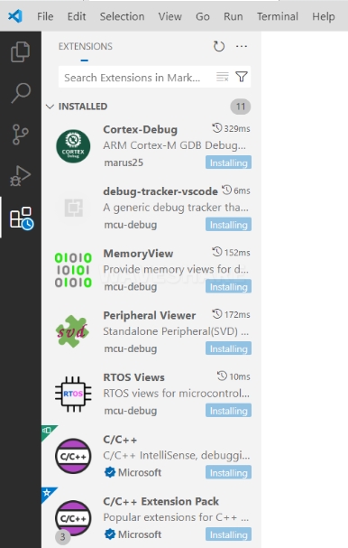
- The text in the right lower corner shows that the installation is complete. Close VSCode
Configure Extension
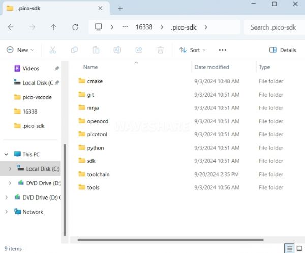
- Open directory C:\Users\username and copy the entire .pico-sdk to that directory
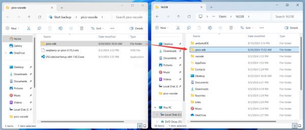
- The copy is completed
- Open vscode and configure the paths for the Raspberry Pi Pico extensions
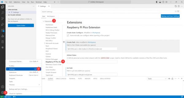
The configuration is as follows:Cmake Path: ${HOME}/.pico-sdk/cmake/v3.28.6/bin/cmake.exe Git Path: ${HOME}/.pico-sdk/git/cmd/git.exe Ninja Path: ${HOME}/.pico-sdk/ninja/v1.12.1/ninja.exe Python3 Path: ${HOME}/.pico-sdk/python/3.12.1/python.exe
New Project
- The configuration is complete, create a new project, enter the project name, select the path, and click Create to create the project
To test the official example, you can click on the Example next to the project name to select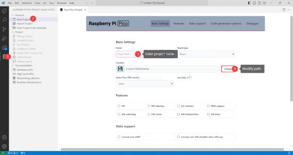
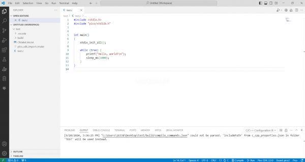
- The project is created successfully
Compile Project
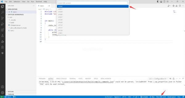
- Select the SDK version
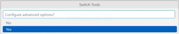
- Select Yes for advanced configuration
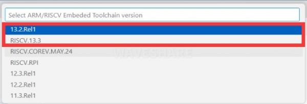
- Choose the cross-compilation chain, 13.2.Rel1 is applicable for ARM cores, RISCV.13.3 is applicable for RISCV cores. You can select either based on your requirements
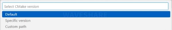
- Select Default for CMake version (the path configured earlier)
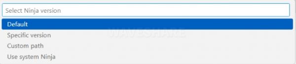
- Select Default for Ninjaversion
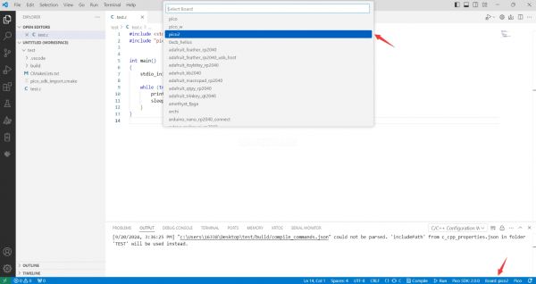
- Select the development board
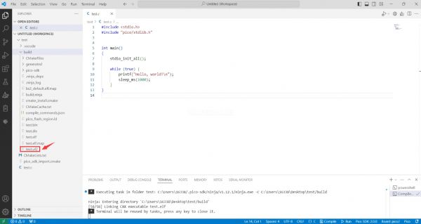
- Click Complie to compile
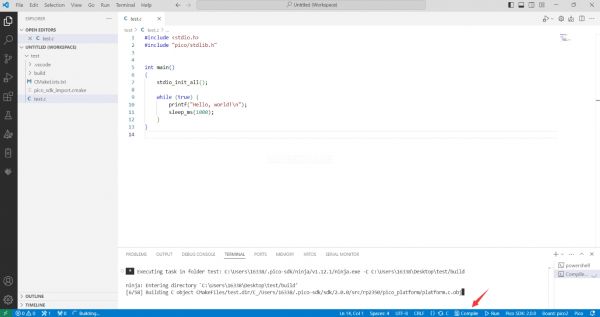
- The uf2 format file is successfully compiled
Flash Firmware
Here are two methods for flashing firmware
- Flash firmware using the pico-vscode plugin
Connect the development board to the computer, click Run to flash the firmware directly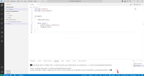
- Flash the firmware manually
1. Press and hold the Boot button
2. Connect the development board to the computer
3. Then the computer will recognize the development board as a USB device.
4. Copy the .uf2 file to the USB drive, and the device will automatically restart, indicating successful program flashing.
Import Project
- Select the project directory and import the project
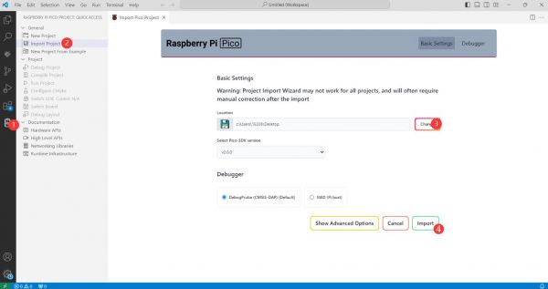
- The Cmake file of the imported project cannot have Chinese (including comments), otherwise the import may fail
- To import your own project, you need to add a line of code to the Cmake file to switch between pico and pico2 normally, otherwise even if pico2 is selected, the compiled firmware will still be suitable for pico
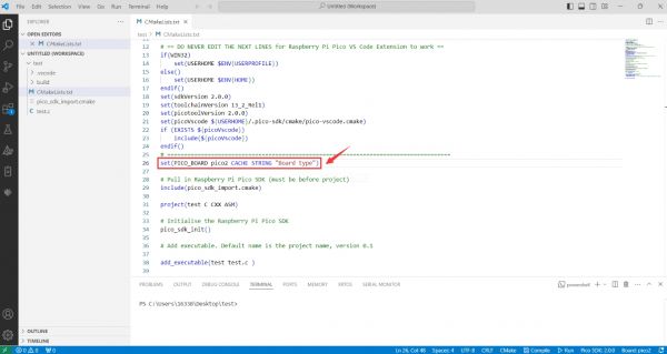
set(PICO_BOARD pico CACHE STRING "Board type")
Update Extension
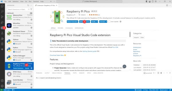
- The extension version in the offline package is 0.15.2, and you can also choose to update to the latest version after the installation is complete
Arduino IDE Series
Install Arduino IDE
- First, go to Arduino official website to download the installation package of the Arduino IDE.
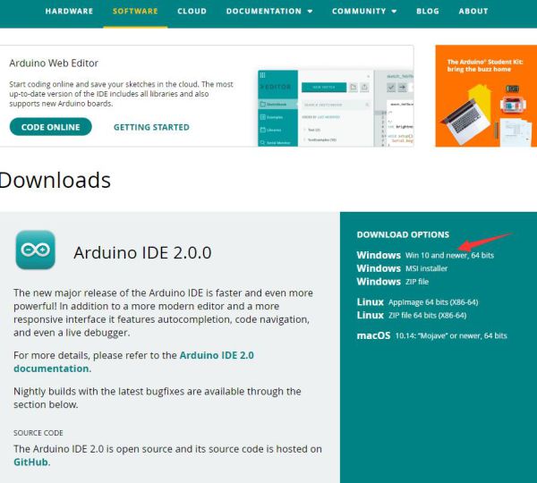
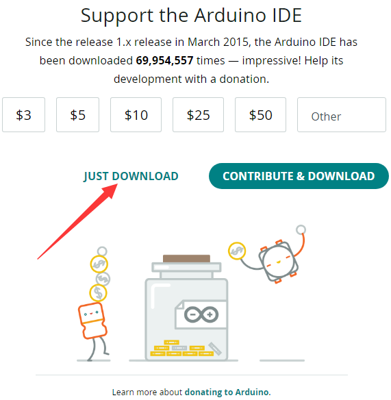
- Here, you can select Just Download.
- Once the download is complete, click Install.
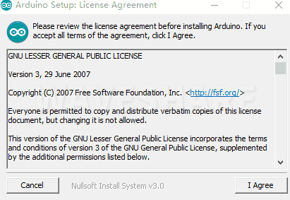
Notice: During the installation process, it will prompt you to install the driver, just click Install
Arduino IDE Interface
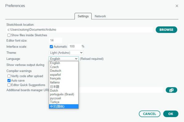
- After the first installation, when you open the Arduino IDE, it will be in English. You can switch to other languages in File --> Preferences, or continue using the English interface.

- In the Language field, select the language you want to switch to, and click OK.
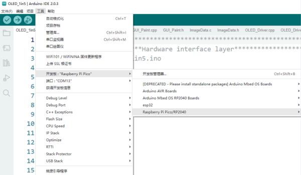
Install Arduino-Pico Core in Arduino IDE
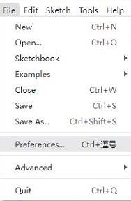
- Open the Arduino IDE, click on the file in the top left corner, and select Preferences
- Add the following link to the attached board manager URL, and then click OK
This link already includes board versions such as RP2040 and RP2350. Please visit arduino-pico for the latest version fileshttps://github.com/earlephilhower/arduino-pico/releases/download/4.5.2/package_rp2040_index.json
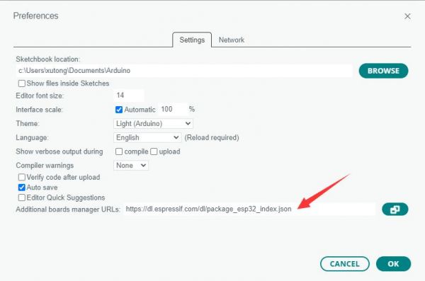
Note: If you already have an ESP32 board URL, you can use a comma to separate the URLs as follows:https://dl.espressif.com/dl/package_esp32_index.json,https://github.com/earlephilhower/arduino-pico/releases/download/4.5.2/package_rp2040_index.json
- Click Tools > Development Board > Board Manager > Search pico, as my computer has already been installed, it shows that it is installed
Upload Demo at the First Time
- Press and hold the BOOTSET button on the Pico board, connect the pico to the USB port of the computer via the Micro USB cable, and release the button after the computer recognizes a removable hard disk (RPI-RP2).
- Download the program and open D1-LED.ino under the arduino\PWM\D1-LED path
- Click Tools --> Port, remember the existing COM, do not click this COM (the COM displayed is different on different computers, remember the COM on your own computer)
- Connect the driver board to the computer using a USB cable. Then, go to Tools > Port. For the first connection, select uf2 Board. After uploading, when you connect again, an additional COM port will appear
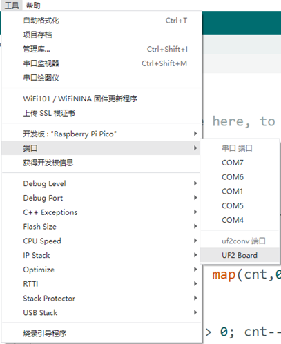
- Click Tools > Development Board > Raspberry Pi Pico > Compatible versions (Raspberry Pi Pico, Raspberry Pi Pico 2, etc.)

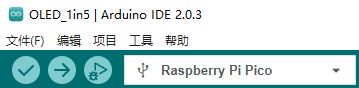
- After setting it up, click the right arrow to upload the program
- If issues arise during this period, and if you need to reinstall or update the Arduino IDE version, it is necessary to uninstall the Arduino IDE completely. After uninstalling the software, you need to manually delete all contents within the C:\Users\[name]\AppData\Local\Arduino15 folder (you need to show hidden files to see this folder). Then, proceed with a fresh installation.
Open Source Demos
MircoPython video demo (github)
MicroPython firmware/Blink demos (C)
Raspberry Pi official C/C++ demo (github)
Raspberry Pi official micropython demo (github)
Arduino official C/C++ demo (github)
Example Experiments
Download the Demo to your computer desktop to conduct some interesting experiments.
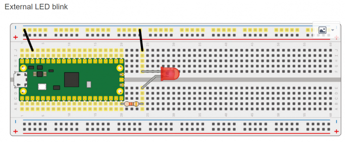
External LED Experiment
- Connect the hardware according to the figure below, connect the Micro USB connected to the computer, open the python file in the demo Lesson-5 External LED in Thonny, and you can see that the red light is flashing when you run the demo.
- Precautions for use: The longer pin of the LED is the positive pole, the shorter one is the negative pole, the negative pole should be connected to GND, the positive pole should be connected to the GPIO output port, and the resistor must be connected when using.
- Code analysis
led_external = machine.Pin(15, machine.Pin.OUT) #Set GP15 to output mode
while True:
   led_external.toggle() #Change the state of the LED light every 5 seconds
   utime.sleep(5)
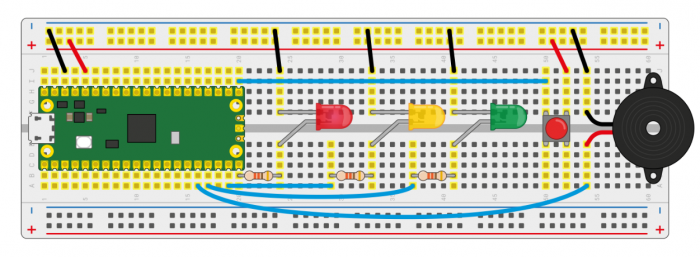
Traffic Light System Experiment
- Connect the hardware according to the figure below, connect the Micro USB connected to the computer, open the python file in the demo Lesson-9 Traffic-Light-System in Thonny, run the demo to see the traffic lights running normally, and the buzzer will be triggered when the button is pressed.
- Precautions for use: The longer pin of the LED is the positive pole, the shorter pin is the negative pole, the negative pole should be connected to GND, the positive pole should be connected to the GPIO output port, and the resistor must be connected when using. The red wire of the buzzer is connected to the GPIO port output, and the black wire is connected to GND.
- Code analysis
def button_reader_thread():  #Detect if a button is pressed
   global button_pressed
   while True:
       if button.value() == 1:
           button_pressed = True

_thread.start_new_thread(button_reader_thread, ()) #Use the thread to detect keystrokes
while True:
   if button_pressed == True: #If the button is pressed, the red light lights up and the buzzer alarms
       led_red.value(1)
       for i in range(10):
           buzzer.value(1)
           utime.sleep(0.2)
           buzzer.value(0)
           utime.sleep(0.2)
       global button_pressed
       button_pressed = False
   led_red.value(1)  #In normal circumstances, when the light turns from red to green, the yellow light will be on for two seconds, then the yellow light and red light will go off, and the green light will be on
   utime.sleep(5)     #When the light turns from green to red, the green light goes off first, the yellow light is on for two seconds, and then the red light is on
   led_amber.value(1)
   utime.sleep(2)
   led_red.value(0)
   led_amber.value(0)
   led_green.value(1)
   utime.sleep(5)
   led_green.value(0)
   led_amber.value(1)
   utime.sleep(5)
   led_amber.value(0)
Burglar Alarm LED Buzzer Experiment
- Connect the hardware according to the figure below, connect the Micro USB connected to the computer, open the python file in the demo Lesson-14 Burglar Alarm LED Buzzer in Thonny, run the demo and you can see that when you move in front of the Passive infrared sensor, the LED light will flash and the buzzer will sound an alarm.
Precautions for use: The middle pin of the Passive infrared sensor is the data output pin, and the pins on both sides can be connected to VCC and GND respectively.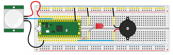
- Code analysis
def pir_handler(pin):  #Interrupt handling function, the buzzer sounds, the LED rapidly flashes
   print("ALARM! Motion detected!")
   for i in range(50):
       led.toggle()
       buzzer.toggle()
       utime.sleep_ms(100)
sensor_pir.irq(trigger=machine.Pin.IRQ_RISING, handler=pir_handler) #Turn on the interrupt, and when the human sensor detects an exception, it will enter the interrupt handling function for processing
while True:  #If there is no exception, the state of LDE will be changed every 5 seconds
   led.toggle()
   utime.sleep(5)
Potentiometer Experiment
- Connect the hardware according to the figure below, connect the Micro USB connected to the computer, open the python file in the demo Lesson-16 Potentiometer in Thonny, run the demo, and rotate the potentiometer to see that the voltage value printed out in the Sheel window is also changing.
Precautions for use: The middle pin of the Potentiometer is the data output pin, and the pins on both sides can be connected to VCC and GND respectively.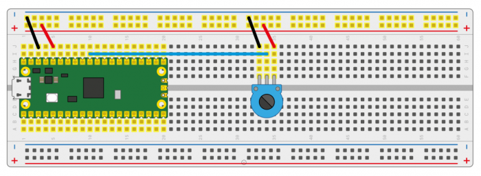
- Code analysis
potentiometer = machine.ADC(26) #Use GP26 as the analog signal collection pin
conversion_factor = 3.3 / (65535)
while True:
   voltage = potentiometer.read_u16() * conversion_factor #Format the collected data and convert it into a voltage value
   print(voltage) #Print the voltage information, the voltage value will change as the sliding varistor rotates
   utime.sleep(2)
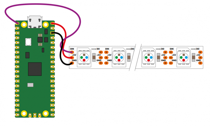
WS2812 Experiment
- Connect the hardware according to the figure below, connect the Micro USB connected to the computer, open the WS2812_RGB_LED.py file in the demo Lesson-25 WS2812 in Thonny, run the demo to see the RGB colors of blue, red, green, and white at once.
- Code analysis
#This code uses the state machine mechanism, the following code is a decorator, in which we can initialize the hardware, set the level of the pins, etc.
#label("bitloop") We can define labels in the code to facilitate our execution by jumping to them.
#jmp(not_x,"do_zero") When x=0, we adjust to the label "do_zero".
#nop() .set(0) [T2 - 1] When x=0, it will jump here to execute.
@asm_pio(sideset_init=PIO.OUT_LOW, out_shiftdir=PIO.SHIFT_LEFT, autopull=True, pull_thresh=24)
def ws2812():
   T1 = 2
   T2 = 5
   T3 = 1
   label("bitloop")
   out(x, 1)               .side(0)    [T3 - 1]
   jmp(not_x, "do_zero")   .side(1)    [T1 - 1]
   jmp("bitloop")          .side(1)    [T2 - 1]
   label("do_zero")
   nop()                   .side(0)    [T2 - 1]
# Create the StateMachine with the ws2812 program, outputting on Pin(22).
sm = StateMachine(0, ws2812, freq=8000000, sideset_base=Pin(0)) #Create a state machine
# Start the StateMachine, it will wait for data on its FIFO.
sm.active(1) #Start state machine
# Display a pattern on the LEDs via an array of LED RGB values.
ar = array.array("I", [0 for _ in range(NUM_LEDS)])
print(ar)
print("blue")
for j in range(0, 255):
   for i in range(NUM_LEDS):
       ar[i] = j
   sm.put(ar,8)  The method of #put() is to put the data into the output FIFO of the state machine
   time.sleep_ms(5)
LCD1602 I2C Experiment
- Connect the hardware according to the figure below, connect the Micro USB connected to the computer, open the python file in the demo Lesson-21 LCD1602 I2C in Thonny, save the RGB1602.py file as a Raspberry Pi Pico, and run the Choose_ Color.py to see a different color switch every 5 seconds; run Discoloration.py file to see the RGB color gradient effect.
- Code analysis
Choose_Color.py
#Define color
rgb9 = (0,255,0) #Green
lcd.setCursor(0, 0) #Set cursor position
# print the number of seconds since reset:
lcd.printout("Waveshare") #Write characters
lcd.setCursor(0, 1) #Set the cursor position to the second row and the zero column
lcd.printout("Hello,World!") #Write characters
lcd.setRGB(rgb1[0],rgb1[1],rgb1[2]); #Set the backlight
Discoloration.py
t=0
while True:

   r = int((abs(math.sin(3.14*t/180)))*255); #RGB changes over time
   g = int((abs(math.sin(3.14*(t+60)/180)))*255);
   b = int((abs(math.sin(3.14*(t+120)/180)))*255);
   t = t + 3;
   lcd.setRGB(r,g,b); #Reset the RGB value
# set the cursor to column 0, line 1
   lcd.setCursor(0, 0) #Navigate to the first row and the zero column
# print the number of seconds since reset:
   lcd.printout("Waveshare") #Write characters
   lcd.setCursor(0, 1) #Navigate to the second row and the zero column
   lcd.printout("Hello,World!") #Write characters
   time.sleep(0.3)
Resources
Official Resources
Demo
- Raspberry-Pi-Pico-Basic-Kit Demo
- Raspberry-Pi-Pico-Sensors_Pack Demo
- Raspberry-Pi-Pico-Sensors_Kit Demo
Pico 2 W
Schematic diagram and datasheets
Firmware library
Pico2
User manuals
Schematic diagram and datasheets
- Pico2 Schematic diagram
- Pico2 Pinout definition
- Pico2 Datasheet
- RP2350 Datasheet
- RP2350 Hardware Design Reference Manual
Related books
Raspberry Pi open source demos
FAQ
Question: What are the common issues and precautions when using Raspberry Pi Pico 2 and Raspberry Pi Pico-2-W for development?
You can refer to the official manual Pico FAQs
Question: Is there interference with Raspberry Pi Pico 2 W?
1. The pin that sets the input state must be initialized to pull up or down
2. Replace the USB cable and see if the USB cable is the one causing the problem
Question: Raspberry Pi Pico 2 GPIO is configured as a pull-down input, why does reading IO show a high voltage level when the pin is left unconnected?
You can refer to the RP2350-E9 section in the RP2350 Datasheet
Support
Monday-Friday (9:30-6:30) Saturday (9:30-5:30)
Email: services01@spotpear.com
[Tutorial Navigation]
- Overview
- Introduction
- Features
- Pinout Definition
- Dimensions
- Pico Getting Started
- Firmware Download
- Basic Introduction
- MicroPython Series
- C/C++ Series
- Install VSCode
- Install Extension
- Configure Extension
- New Project
- Compile Project
- Flash Firmware
- Import Project
- Update Extension
- Arduino IDE Series
- Install Arduino IDE
- Arduino IDE Interface
- Install Arduino-Pico Core in Arduino IDE
- Upload Demo at the First Time
- Open Source Demos
- Example Experiments
- External LED Experiment
- Traffic Light System Experiment
- Burglar Alarm LED Buzzer Experiment
- Potentiometer Experiment
- WS2812 Experiment
- LCD1602 I2C Experiment
- Resources
- FAQ
- Question: What are the common issues and precautions when using Raspberry Pi Pico 2 and Raspberry Pi Pico-2-W for development?
- Question: Is there interference with Raspberry Pi Pico 2 W?
- Question: Raspberry Pi Pico 2 GPIO is configured as a pull-down input, why does reading IO show a high voltage level when the pin is left unconnected?
- Support