


- sales/support
Google Chat:---
- sales
+86-0755-88291180
- sales01
sales@spotpear.com
- sales02
dragon_manager@163.com
- support
tech-support@spotpear.com
- CEO-Complaints
zhoujie@spotpear.com
- Only Tech-Support
WhatsApp:13246739196
- Purchase/Shipping/Refund
WhatsApp:13424403025
RP2350-Matrix User Guide
Overview
Introduction
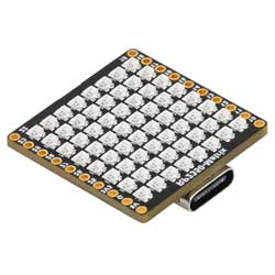
The RP2350-Matrix is a low-cost, high-performance microcontroller development board designed by Waveshare. In a smaller board size, it uses RP2350 as the main controller, incorporating a 6-axis IMU (three-axis accelerometer and three-axis gyroscope) and an 8×8 RGB LED matrix. It integrates 16MB of on-chip Flash for easy development and integration into products.
Features
- RP2350A microcontroller chip officially designed by Raspberry Pi
- Unique dual-core and dual-architecture design, equipped with dual-core ARM Cortex-M33 processor and dual-core Hazard3 RISC-V processor, flexible clock running up to 150 MHz, supporting flexible switching between the two architectures
- Built-in 520KB of SRAM and 16MB of on-chip Flash
- Type-C port, easier to use
- Onboard QMI8658 6-axis IMU (3-axis accelerometer and 3-axis gyroscope)
- Onboard 8 × 8 RGB LED matrix for cool lighting effects
- Bring out the Dout pin to connect an extended RGB matrix
- USB1.1 host and slave device support
- Low-power sleep and dormant modes
- Drag-and-drop programming via USB mass storage
- 25 × multi-functional GPIO pins
- 1 x HSTX, 2 x SPI, 2 x I2C, 2 x UART, 4 × 12-bit ADC and 16 × controllable PWM channels
- Accurate clock and timer on-chip
- Temperature sensor
- On-chip accelerated floating-point library
- 12 × Programmable I/O (PIO) state machines for custom peripheral support
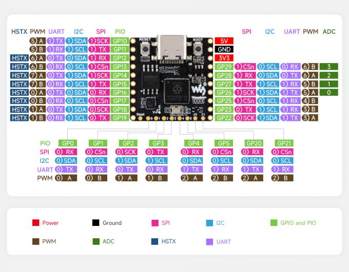
Pinout Definition
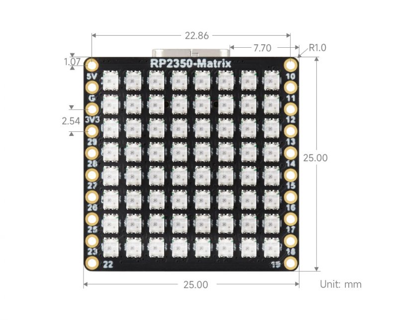
Dimensions
Precautions
- When the RGB LED matrix is fully lit at maximum brightness, the current is about 900mA, and it is recommended to use a power adapter above 1A
- When the RGB LED matrix is fully lit, avoid direct eye contact and do not touch the RGB LED beads
- It is not recommended to keep the RGB LED matrix fully lit for long periods, as it can cause the LEDs to accumulate heat and become overheated, which can reduce the lifespan of the LED beads or cause them to burn out
- It is recommended to refer to the 03-TempCtrl example for a fully bright RGB LED matrix. Intelligent brightness control based on core temperature can effectively prevent the development board from overheating
Pico Getting Started
Firmware Download
- MicroPython Firmware Download

- C_Blink Firmware Download

Basic Introduction
MicroPython Series
Install Thonny IDE
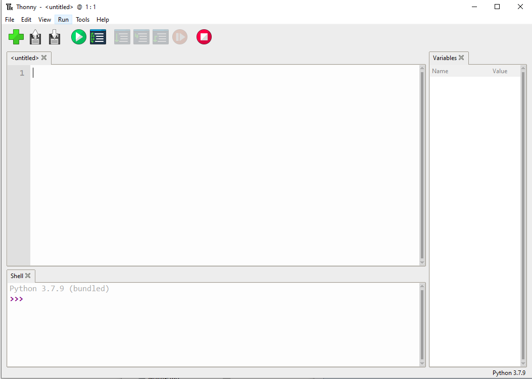
To facilitate the development of Pico/Pico2 boards with MicroPython on a computer, it is recommended to download the Thonny IDE
- Download Thonny IDE and follow the steps to install, the installation packages are all Windows versions, please refer to Thonny's official website for other versions
- After installation, configure the language and motherboard environment for the first use. Since we are using Pico/Pico2, pay attention to selecting the Raspberry Pi option for the motherboard environment
- Configure MicroPython environment and choose Pico/Pico2 port
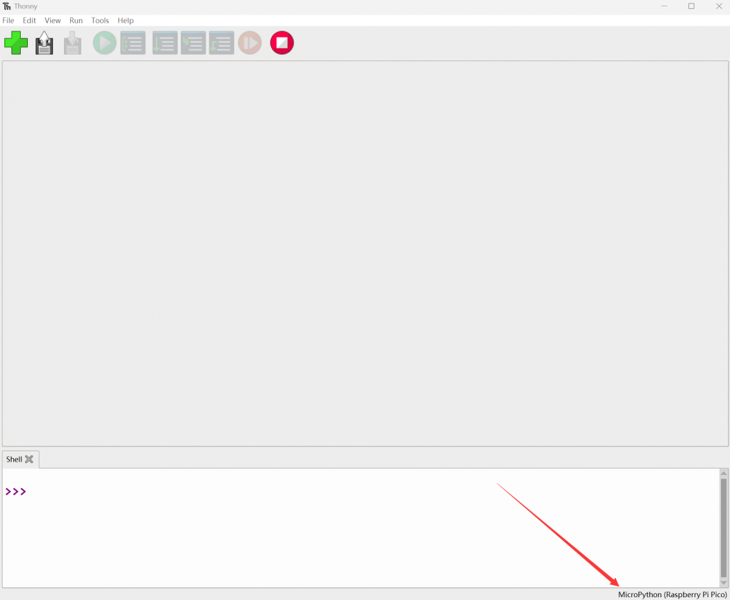
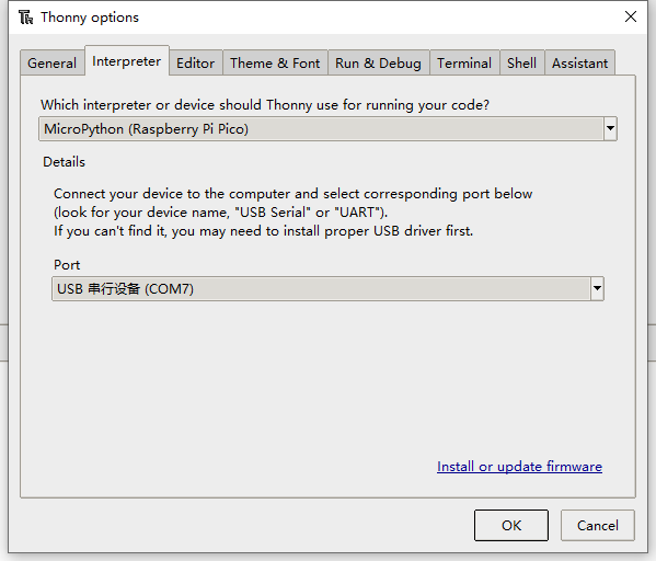
- Connect Pico/Pico2 to your computer first, and in the lower right corner of Thonny left-click on the configuration environment option --> select Configure interpreter
- In the pop-up window, select MicroPython (Raspberry Pi Pico), and choose the corresponding port
Flash Firmware
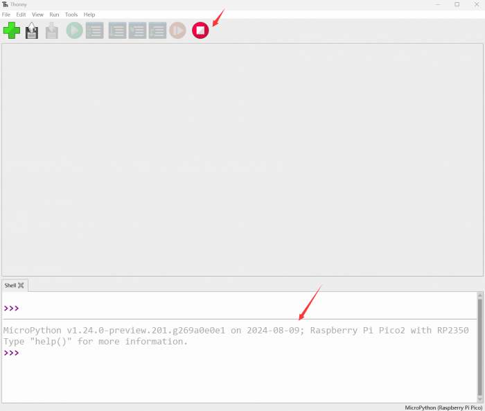
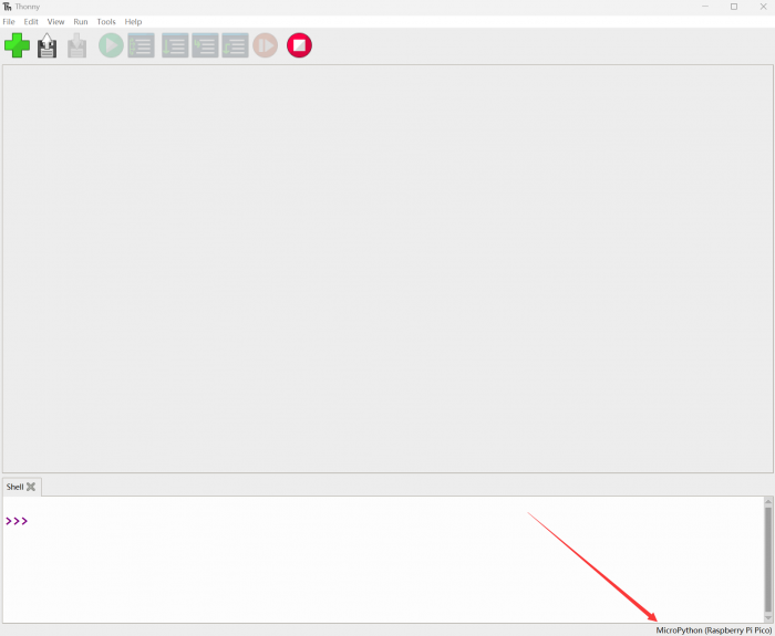
- Click OK to return to the Thonny main interface, download the corresponding firmware library and burn it to the device, and then click the Stop button to display the current environment in the Shell window
- Note: Flashing the Pico2 firmware provided by MicroPython may cause the device to be unrecognized, please use the firmware below or in the package
- How to download the firmware library for Pico/Pico2 in windows: After holding down the BOOT button and connecting to the computer, release the BOOT button, a removable disk will appear on the computer, copy the firmware library into it
- How to download the firmware library for RP2040/RP2350 in windows: After connecting to the computer, press the BOOT key and the RESET key at the same time, release the RESET key first and then release the BOOT key, a removable disk will appear on the computer, copy the firmware library into it (you can also use the Pico/Pico2 method)
MicroPython Series Tutorials
【MicroPython】 machine.Pin class function details
【MicroPython】machine.PWM class function details
【MicroPython】machine.ADC class function details
【MicroPython】machine.UART class function details
【MicroPython】machine.I2C class function details
【MicroPython】machine.SPI class function details
【MicroPython】rp2.StateMachine class function details
C/C++ Series
For C/C++, it is recommended to use Pico VSCode for development. This is a Microsoft Visual Studio Code extension designed to make it easier for you to create, develop, and debug projects for the Raspberry Pi Pico series development boards. No matter if you are a beginner or an experienced professional, this tool can assist you in developing Pico with confidence and ease. Here's how to install and use the extension.
- Official website tutorial: https://www.raspberrypi.com/news/pico-vscode-extension/
- This tutorial is suitable for Raspberry Pi Pico, Pico2 and the RP2040 and RP2350 series development boards developed by Waveshare
- The development environment defaults to Windows11. For other environments, please refer to the official tutorial for installation
Install VSCode
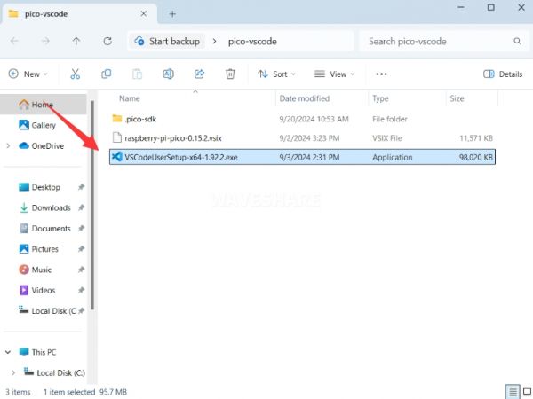
- First, click to download pico-vscode package, unzip and open the package, double-click to install VSCode
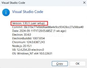
Note: If vscode is installed, check if the version is v1.87.0 or later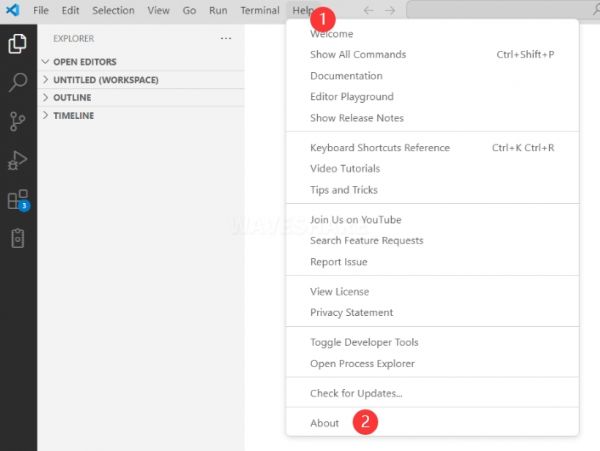
Install Extension
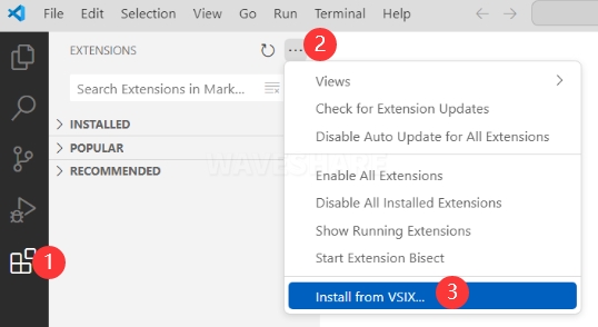
- Click Extensions and select Install from VSIX
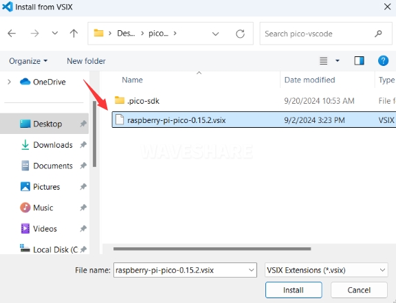
- Select the package with the vsix suffix and click Install
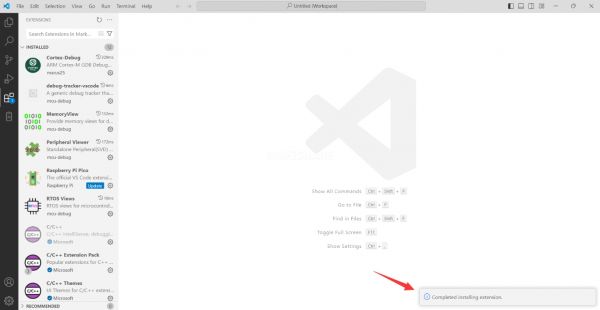
- Then vscode will automatically install raspberry-pi-pico and its dependency extensions, you can click Refresh to check the installation progress
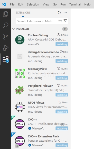
- The text in the right lower corner shows that the installation is complete. Close VSCode
Configure Extension
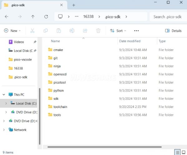
- Open directory C:\Users\username and copy the entire .pico-sdk to that directory
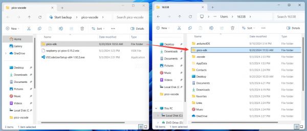
- The copy is completed
- Open vscode and configure the paths for the Raspberry Pi Pico extensions
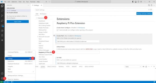
The configuration is as follows:Cmake Path: ${HOME}/.pico-sdk/cmake/v3.28.6/bin/cmake.exe Git Path: ${HOME}/.pico-sdk/git/cmd/git.exe Ninja Path: ${HOME}/.pico-sdk/ninja/v1.12.1/ninja.exe Python3 Path: ${HOME}/.pico-sdk/python/3.12.1/python.exe
New Project
- The configuration is complete, create a new project, enter the project name, select the path, and click Create to create the project
To test the official example, you can click on the Example next to the project name to select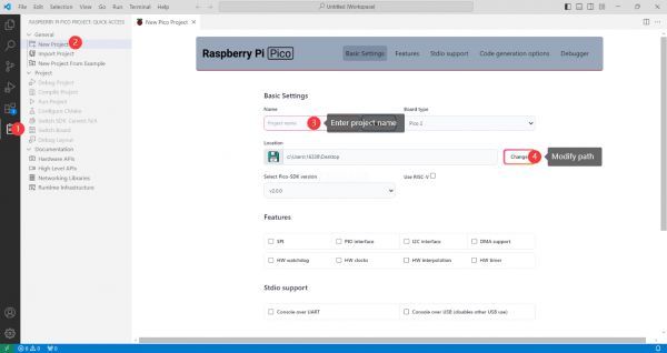
- The project is created successfully
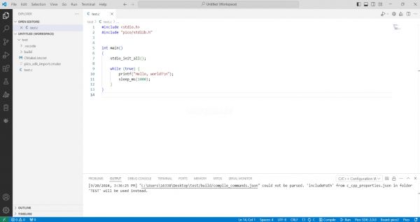
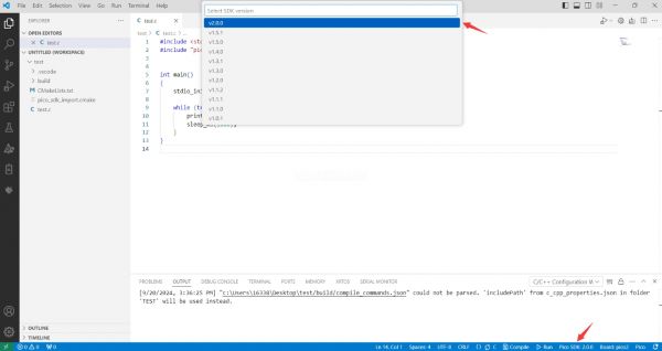
Compile Project
- Select the SDK version
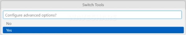
- Select Yes for advanced configuration
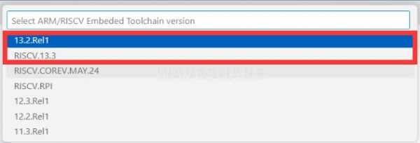
- Choose the toolchain, 13.2.Rel1 is applicable for ARM cores, RISCV.13.3 is applicable for RISCV cores. You can select either based on your requirements
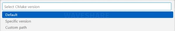
- Select Default for CMake version (the path configured earlier)
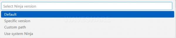
- Select Default for Ninja version
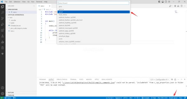
- Select the development board
- Click Compile to compile
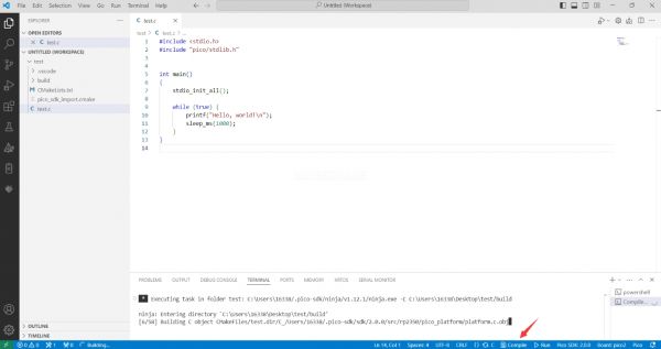
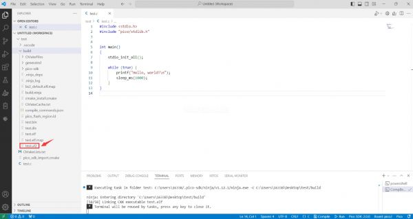
- The uf2 format file is successfully compiled
Flash Firmware
Here are two methods for flashing firmware
- Flash firmware using the pico-vscode plugin
Connect the development board to the computer, click Run to flash the firmware directly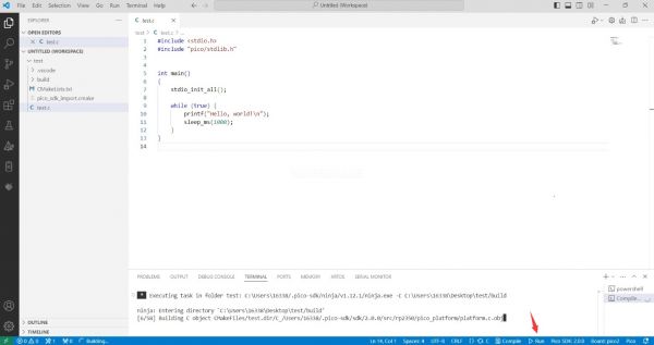
- Flash the firmware manually
1. Press and hold the Boot button
2. Connect the development board to the computer
3. Then the computer will recognize the development board as a USB device.
4. Copy the .uf2 file to the USB drive, and the device will automatically restart, indicating successful program flashing.
Import Project
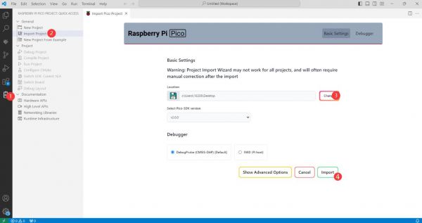
- Select the project directory and import the project
- The Cmake file of the imported project cannot have Chinese (including comments), otherwise the import may fail
- To import your own project, you need to add a line of code to the Cmake file to switch between pico and pico2 normally, otherwise even if pico2 is selected, the compiled firmware will still be suitable for pico
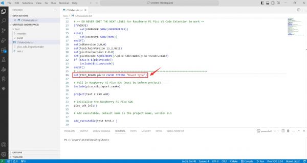
set(PICO_BOARD pico CACHE STRING "Board type")
Update Extension
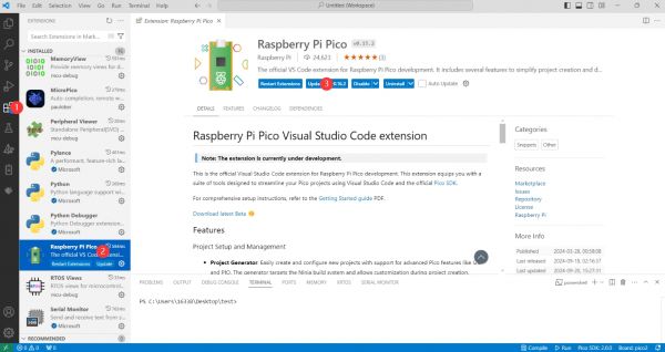
- The extension version in the offline package is 0.15.2, and you can also choose to update to the latest version after the installation is complete
Arduino IDE Series
Install Arduino IDE
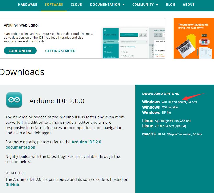
- First, go to Arduino official website to download the installation package of the Arduino IDE.
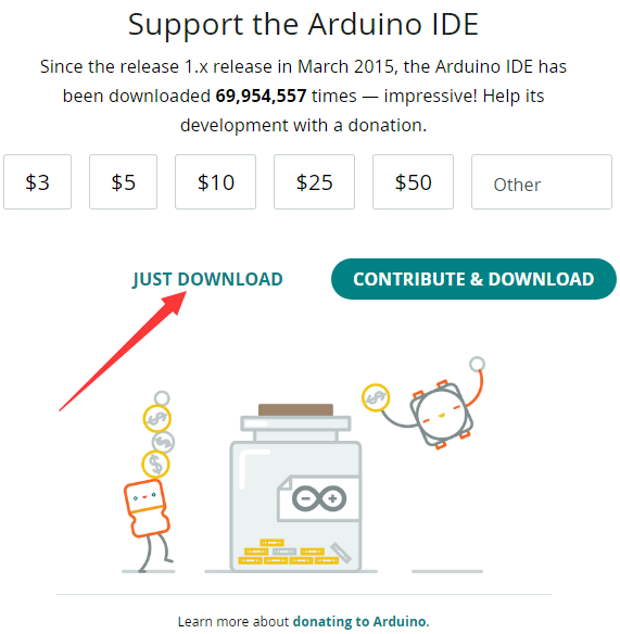
- Here, you can select Just Download.
- Once the download is complete, click Install.
Notice: During the installation process, it will prompt you to install the driver, just click Install
Arduino IDE Interface
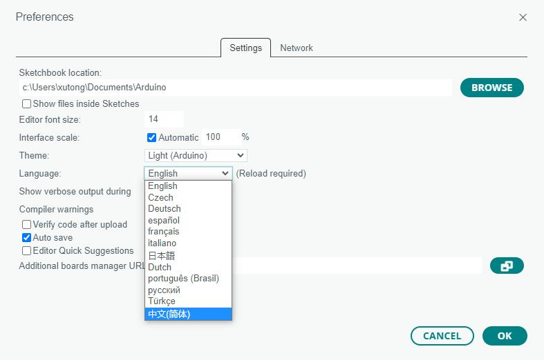
- After the first installation, when you open the Arduino IDE, it will be in English. You can switch to other languages in File --> Preferences, or continue using the English interface.

- In the Language field, select the language you want to switch to, and click OK.
Install Arduino-Pico Core in Arduino IDE
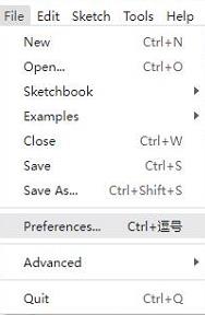
- Open the Arduino IDE, click on the file in the top left corner, and select Preferences
- Add the following link to the attached board manager URL, and then click OK
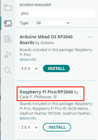
This link already includes board versions such as RP2040 and RP2350. Please visit arduino-pico for the latest version fileshttps://github.com/earlephilhower/arduino-pico/releases/download/4.5.2/package_rp2040_index.json
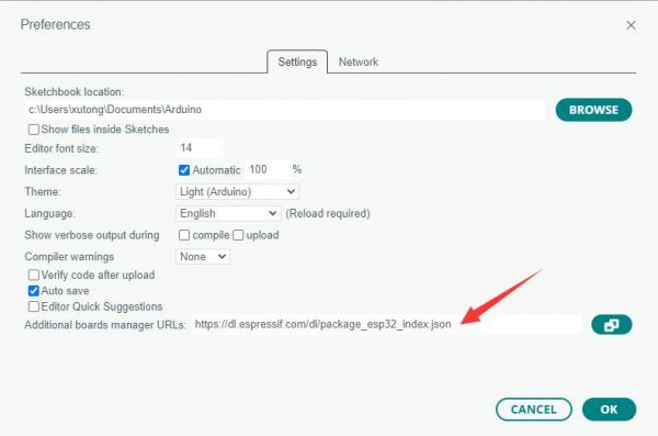
Note: If you already have an ESP32 board URL, you can use a comma to separate the URLs as follows:https://dl.espressif.com/dl/package_esp32_index.json,https://github.com/earlephilhower/arduino-pico/releases/download/4.5.2/package_rp2040_index.json
- Click Tools > Development Board > Board Manager > Search pico, as my computer has already been installed, it shows that it is installed
Upload Demo at the First Time
- Press and hold the BOOTSET button on the Pico board, connect the pico to the USB port of the computer via the Micro USB cable, and release the button after the computer recognizes a removable hard disk (RPI-RP2).
- Download the program and open D1-LED.ino under the arduino\PWM\D1-LED path
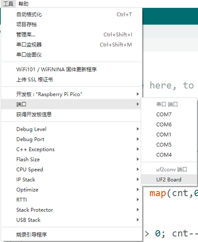
- Click Tools --> Port, remember the existing COM, do not click this COM (the COM displayed is different on different computers, remember the COM on your own computer)
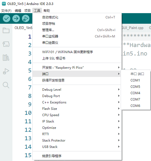
- Connect the driver board to the computer using a USB cable. Then, go to Tools > Port. For the first connection, select uf2 Board. After uploading, when you connect again, an additional COM port will appear
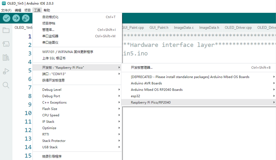
- Click Tools > Development Board > Raspberry Pi Pico > Corresponding models (Raspberry Pi Pico, Raspberry Pi Pico 2, etc.)

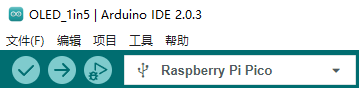
- After setting it up, click the right arrow to upload the program
- If issues arise during this period, and if you need to reinstall or update the Arduino IDE version, it is necessary to uninstall the Arduino IDE completely. After uninstalling the software, you need to manually delete all contents within the C:\Users\[name]\AppData\Local\Arduino15 folder (you need to show hidden files to see this folder). Then, proceed with a fresh installation.
Open Source Demos
MircoPython video demo (github)
MicroPython firmware/Blink demos (C)
Raspberry Pi official C/C++ demo (github)
Raspberry Pi official MicroPython demo (github)
Arduino official C/C++ demo (github)
Demo
C/C++ Demo
01-Colorful
Demo description
- This example implements a gradient color display effect on an RGB LED matrix
Code description
- Function description
WS2812_init(): Initialize the RGB LED control pins and configure the relevant parametersWS2812_show2(uint8_t r, uint8_t g, uint8_t b): Refresh all RGB LEDs based on the input color
- Parameter description
- In the
WS2812.hfile, there are four parameters that can be configured:NUM_LEDS: Number of RGB LEDsLED_BRIGHTNESS: Maximum Brightness of RGB LEDWIDTH: RGB LED matrix widthHEIGHT: RGB LED matrix height
- In the
- Logical flow
- Gradient is achieved by setting three color components: red, green, and blue.
- Red->Green Gradient: First set the red component
rto its maximum value, and set the blue and green componentsg, bto zero. In the loop, decrease the red component and increase the green component to achieve a red to green gradient - Green-> Blue Gradient: First set the green component
gto its maximum value, and set the red and blue componentsr, bto zero. In the loop, decrease the green component and increase the blue component to achieve a green to blue gradient - Blue->Red Gradient: First set the blue component
bto its maximum value, and set the green and red componentsg, rto zero. In the loop, decrease the blue component and increase the red component to achieve a blue to red gradient
- Red->Green Gradient: First set the red component
- Gradient is achieved by setting three color components: red, green, and blue.
02-Game
Demo description
- This example implements control for a single RGB LED to move towards the tilt direction of the board
Coordinate description
- The program is configured such that when the USB port is facing upward, the top left corner of the matrix is (0,0) and the bottom right corner is (7,7). The vertical direction is the X-axis, and the positive direction is opposite to the X-axis of the 6-axis IMU. The horizontal direction is the Y-axis, and the positive direction is the same as the Y-axis of the 6-axis IMU
Code description
- Function description
WS2812_init(): Initialize the RGB LED control pins and configure the relevant parametersQMI8658_init(): Initialize the 6-axis IMUQMI8658_read_xyz(): Read 6-axis IMU dataWS2812_clear(): Zero out the RGB LED arrayledsWS2812_set_pixel(uint8_t x, uint8_t y, uint8_t r, uint8_t g, uint8_t b): Set LED color at (x,y)WS2812_show(): Refresh the RGB LED matrix according toledsarray
- Logical flow
- Acquire 6-axis IMU data through
QMI8658_read_xyzand control RGB LED movement based on the acquired X and Y axis acceleration data.- X-axis direction movement: Determine the movement direction based on the X-axis acceleration data
acc[0]. Whenacc[0]is greater than the movement thresholdthreshold, the x-coordinate decreases, and the RGB LED moves up. Whenacc[0]is less than the movement threshold-threshold, the x-coordinate increases, and the RGB LED moves downward - Y-axis direction movement: Determine the movement direction based on the Y-axis acceleration data
acc[1]. Whenacc[1]is greater than the movement thresholdthreshold, the y-coordinate increases, and the RGB LED moves to the right. Whenacc[1]is less than the movement threshold-threshold, the y-coordinate decreases, and the RGB LED moves to the left
- X-axis direction movement: Determine the movement direction based on the X-axis acceleration data
- Acquire 6-axis IMU data through
03-TempCtrl
Demo description
- This example implements automatic control of RGB LED brightness based on core temperature
Safety tips
- 1. Initial brightness: The brightness is 100% when the device is started, and direct eye contact with LED lights should be avoided
- 2. Power requirements: The maximum brightness power consumption of the full brightness is about 900mA. Please use a 5V power supply with a rated current of ≥1A and a stable output
- 3. Precautions: The surface temperature of the LED will continue to rise to 70°C. Avoid body contact during operation and avoid running at full brightness for extended periods to reduce the lifespan of the LEDs
Code description
- Function description
WS2812_init(): Initialize the RGB LED control pins and configure the relevant parametersWS2812_show2(uint8_t r, uint8_t g, uint8_t b): Refresh all RGB LEDs based on the input colorread_onboard_temperature(): Get the core temperature
- Logical flow
- Get the core temperature through
read_onboard_temperature()and control the brightness change according to the set temperature and brightness arrayBRIGHTNESS_LEVELS- Temperature upshift: After the program starts, the initial temperature level is set to Level 1, and the brightness is 100%. When the core temperature
tempis greater than the next level temperature, the level increases and the brightness decreases. - Temperature downshift: As temperature increases, the brightness will gradually decrease. When the brightness is low enough, the core temperature
tempwill slowly decrease. When the core temperaturetempdrops to the previous temperature level +1°C, the level decreases and the brightness increases.
- Temperature upshift: After the program starts, the initial temperature level is set to Level 1, and the brightness is 100%. When the core temperature
- Get the core temperature through
Micropython Demo
01-Colorful
Demo description
- This example implements a gradient color display effect on an RGB LED matrix
Code description
- Function description
LEDController(): Initialize the RGB LED control pins and configure the relevant parametersled_ctrl.show2(): Refresh all RGB LEDs based on the input color
- Parameter description
- In the
WS2812.pyfile, there are four parameters that can be configured:NUM_LEDS: Number of RGB LEDsLED_BRIGHTNESS: Maximum Brightness of RGB LEDWIDTH: RGB LED matrix widthHEIGHT: RGB LED matrix height
- In the
- Logical flow
- Gradient is achieved by setting three color components: red, green, and blue.
- Red->Green Gradient: First set the red component
rto its maximum value, and set the blue and green componentsg, bto zero. In the loop, decrease the red component and increase the green component to achieve a red to green gradient - Green-> Blue Gradient: First set the green component
gto its maximum value, and set the red and blue componentsr, bto zero. In the loop, decrease the green component and increase the blue component to achieve a green to blue gradient - Blue->Red Gradient: First set the blue component
bto its maximum value, and set the green and red componentsg, rto zero. In the loop, decrease the blue component and increase the red component to achieve a blue to red gradient
- Red->Green Gradient: First set the red component
- Gradient is achieved by setting three color components: red, green, and blue.
02-Game
Demo description
- This example implements control for a single RGB LED to move towards the tilt direction of the board
Coordinate description
- The program is set so that when the USB port is facing up, the top left corner of the matrix is (0,0) and the bottom right corner is (7,7). The vertical direction is the X-axis, and the positive direction is opposite to the X-axis of the 6-axis IMU. The horizontal direction is the Y-axis, and the positive direction is the same as the Y-axis of the 6-axis IMU
Code description
- Function description
LEDController(): Initialize the RGB LED control pins and configure the relevant parametersQMI8658_init(): Initialize the 6-axis IMUimu.Read_XYZ(): Read 6-axis IMU dataled_ctrl.clear(): Zero out the RGB LED arrayledsled_ctrl.set_pixel(): Set LED color at (x,y)led_ctrl.show(): Refresh the RGB LED matrix according toledsarray
- Logical flow
- Acquire 6-axis IMU data through
imu.Read_XYZ()and control RGB LED movement based on the acquired X and Y axis acceleration data.- X-axis direction movement: Determine the movement direction based on the X-axis acceleration data
xyz[0]. Whenxyz[0]is greater than the movement thresholdthreshold, the x-coordinate decreases, and the RGB LED moves up. Whenxyz[0]is less than the movement threshold-threshold, the x-coordinate increases, and the RGB LED moves downward - Y-axis direction movement: Determine the movement direction based on the Y-axis acceleration data
xyz[1]. Whenxyz[1]is greater than the movement thresholdthreshold, the y-coordinate increases, and the RGB LED moves to the right. Whenxyz[1]is less than the movement threshold-threshold, the y-coordinate decreases, and the RGB LED moves to the left
- X-axis direction movement: Determine the movement direction based on the X-axis acceleration data
- Acquire 6-axis IMU data through
03-TempCtrl
Demo description
- This example implements automatic control of RGB LED brightness based on core temperature
Safety tips
- 1. Initial brightness: The brightness is 100% when the device is started, and direct eye contact with LED lights should be avoided
- 2. Power requirements: The maximum brightness power consumption of the full brightness is about 900mA. Please use a 5V power supply with a rated current of ≥1A and a stable output
- 3. Precautions: The surface temperature of the LED will continue to rise to 70°C. Avoid body contact during operation and avoid running at full brightness for extended periods to reduce the lifespan of the LEDs
Code description
- Function description
LEDController(): Initialize the RGB LED control pins and configure the relevant parametersled_ctrl.show2(): Refresh all RGB LEDs based on the input colorread_onboard_temperature(): Get the core temperature
- Logical flow
- Get the core temperature through
read_onboard_temperature()and control the brightness change according to the set temperature and brightness arrayBRIGHTNESS_LEVELS- Temperature upshift: After the program starts, the initial temperature level is set to Level 1, and the brightness is 100%. When the core temperature
tempis greater than the next level temperature, the level increases and the brightness decreases. - Temperature downshift: As temperature increases, the brightness will gradually decrease. When the brightness is low enough, the core temperature
tempwill slowly decrease. When the core temperaturetempdrops to the previous temperature level +1°C, the level decreases and the brightness increases.
- Temperature upshift: After the program starts, the initial temperature level is set to Level 1, and the brightness is 100%. When the core temperature
- Get the core temperature through
Resources
Supporting Resources
Demo
Schematic Diagram
Datasheets
Official Resources
Raspberry Pi Official Documents
- Get Started with MicroPython on Raspberry Pi Pico
- Raspberry Pi related books download
- Pico2 Schematic diagram
- Pico2 Pinout definition
- Pico2 Getting Started
- Pico2 C SDK User Manual
- Pico2 Python SDK User Manual
- Pico2 Datasheet
- RP2350 Datasheet
- RP2350 Hardware Design Reference Manual
Raspberry Pi Open Source Demos
Development Software
- Thonny Python IDE (Windows version V3.3.3)
- Pico environment building related software
- pico-vscode package
FAQ
Question: Raspberry Pi Pico 2 GPIO is configured as a pull-down input, why does reading IO show a high voltage level when the pin is left unconnected?
You can refer to the RP2350-E9 section in the RP2350 Datasheet
Support
Monday-Friday (9:30-6:30) Saturday (9:30-5:30)
Email: services01@spotpear.com
[Tutorial Navigation]
- Overview
- Introduction
- Features
- Pinout Definition
- Dimensions
- Precautions
- Pico Getting Started
- Firmware Download
- Basic Introduction
- MicroPython Series
- C/C++ Series
- Install VSCode
- Install Extension
- Configure Extension
- New Project
- Compile Project
- Flash Firmware
- Import Project
- Update Extension
- Arduino IDE Series
- Install Arduino IDE
- Arduino IDE Interface
- Install Arduino-Pico Core in Arduino IDE
- Upload Demo at the First Time
- Open Source Demos
- Demo
- Resources
- FAQ
- Support