




- sales/support
Google Chat:---
- sales
+86-0755-88291180
- sales01
sales@spotpear.com
- sales02
dragon_manager@163.com
- support
tech-support@spotpear.com
- CEO-Complaints
zhoujie@spotpear.com
- Only Tech-Support
WhatsApp:13246739196
- Purchase/Shipping/Refund
WhatsApp:13424403025
- HOME
- >
- ARTICLES
- >
- Common Moudle
- >
- ESP
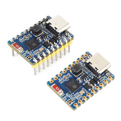
ESP32-C6-Zero-B User Guide
Features
- Powered by the ESP32-C6FH8 chip, integrating a high-performance and a low-power dual-core 32-bit RISC-V processor running at up to 160 MHz and 20 MHz respectively
- Built-in 320 KB ROM, 512 KB HP SRAM, 16 KB LP SRAM, and 8 MB Flash storage
- Integrated Wi-Fi 6, Bluetooth 5, and IEEE 802.15.4 (Zigbee 3.0 and Thread) wireless communication with excellent RF performance
- USB Type-C Port, supports plugging in either orientation
- Supports 5-36V wide-voltage input for greater flexibility
- Rich peripheral interfaces with outstanding compatibility and expandability
- Castellated module design for direct soldering onto carrier boards
- Supports multiple low-power modes, allowing flexible adjustment of communication range, data rate, and power consumption for various application scenarios
Functional Block Diagram

Resource Interfaces

- ESP32-C6FH8 RISC-V 32-bit dual-core processor (HP core up to 160MHz, LP core up to 20MHz)
- SY8301 DC power supply, supports up to 1A output
- USB Type-C Port For program download and debugging
- WS2812 Cool RGB LED
- BOOT Button Hold this button and press the RESET button to enter download mode
- RESET Button
- 2.4G Ceramic Antenna
- Antenna Selection Chip Supports switching between the onboard ceramic antenna (default) and the IPEX 4 antenna socket via GPIO7
- ESP32-C6FH8 Pin
Pinout Definition

Dimensions

Working with Arduino
This chapter contains the following sections. Please read as needed:
Arduino Getting Started
New to Arduino ESP32 development and looking for a quick start? We have prepared a comprehensive Getting Started Tutorial for you.
- Section 0: Getting to Know ESP32
- Section 1: Installing and Configuring Arduino IDE
- Section 2: Arduino Basics
- Section 3: Digital Output/Input
- Section 4: Analog Input
- Section 5: Pulse Width Modulation (PWM)
- Section 6: Serial Communication (UART)
- Section 7: I2C Communication
- Section 8: SPI Communication
- Section 9: Wi-Fi Basics
- Section 10: Web Server
- Section 11: Bluetooth
- Section 12: LVGL GUI Development
- Section 13: Comprehensive Project
Note: This tutorial uses the ESP32-S3-Zero as a reference example, and all hardware code is based on its pinout. Before you start, we recommend checking the pinout of your development board to ensure the pin configuration is correct.
Setting Up the Development Environment
1. Installing and Configuring the Arduino IDE
Please refer to the tutorial Installing and Configuring Arduino IDE to download and install the Arduino IDE and add ESP32 support.
2. Additional Tips
The ESP32-C6-Zero-B supports direct model selection in the Arduino IDE. Choose "Waveshare ESP32-C6-Zero".

The ESP32-C6-Zero-B uses the ESP32-C6 native USB port instead of UART to USB. For serial communication:
The
printf()function can be used directly;To use the
Serial.println()function, the USB CDC feature must be enabled. Please follow the steps below to verify your environment is configured correctly:Update the ESP32 Libraries: It is recommended to update the ESP32 board libraries in Arduino IDE to version 3.3.5 or later. Newer versions of the core have USB CDC enabled by default for this board.
Check Configuration Options: In the Arduino IDE "Tools" menu, check and confirm that the "USB CDC On Boot" option is set to "Enabled".
NOTEAs shown in the image below, the "USB CDC On Boot" option should be set to
Enabledwhen correctly configured.
Working with ESP-IDF
This chapter contains the following sections. Please read as needed:
- ESP-IDF Getting Started
- Setting Up the Development Environment
- Running Official Espressif Examples
- Erasing Device Flash
ESP-IDF Getting Started
New to ESP32 ESP-IDF development and looking to get started quickly? We have prepared a general Getting Started Tutorial for you.
- Section 1: Environment Setup
- Section 2: Running Examples
- Section 3: Creating a Project
- Section 4: Using Components
- Section 5: Debugging
- Section 6: FreeRTOS
- Section 7: Peripherals
- Section 8: Wi-Fi Programming
- Section 9: BLE Programming
Please Note: This tutorial uses the ESP32-S3-Zero as a teaching example, and all hardware code is based on its pinout. Before you start, it is recommended that you check the pinout of your development board to ensure the pin configuration is correct.
Setting Up the Development Environment
The following tutorial is based on the Windows development environment using VS Code.
Note: ESP-IDF supports ESP32-C6 starting from version V5.1. ** When installing ESP-IDF, you must select version V5.1 or later.**
Please refer to Waveshare ESP-IDF Getting Started - Section 1 Set Up Environment to complete the ESP-IDF development environment configuration.
Running Official Espressif Examples
Official Example Usage Tutorial
Creating an Example
Use the shortcut F1 and enter:
esp-idf:show examples projects
Select your current IDF version

Using the Hello World example:
- ① Select the corresponding example
- ② Its readme will indicate which chips the example supports (the usage and file structure are described there, omitted here)
- ③Click to create the example

Choose the path to place the example; the folder name must not already exist
Changing the COM Port
This shows the COM port in use. Click to change it.
Select the appropriate COM port for your device. It is recommended to use the USB COM port (can be checked in Device Manager).
If download fails, press and hold the reset button for more than 1 second, wait for the PC to re-detect the device, then try downloading again.

Select the project or example to use

The COM port is now changed.
Changing the Target Driver
This shows the target driver in use. Click to change it.
Select the project or example to use

Wait a moment after clicking

Select the target we need to drive, namely the main chip ESP32-C6.

Select the openocd path. This does not affect us, so choose any.

Other Status Bar Descriptions
- ① SDK Configuration Editor – many ESP-IDF features and configurations can be modified here.
- ② Full Clean – clean all build files.
- ③ Build
- ④ Current download method – defaults to UART.
- ⑤ Flash current firmware – do this after building.
- ⑥ Open Serial Monitor – to view serial output.
- ⑦ Build, Flash, and Open Serial Monitor combined button (most commonly used for debugging).

Build, Flash, Serial Monitor
Click the Build, Flash, Open Serial Monitor button described earlier.

Building may take a long time, especially on the first build.

During this process, ESP-IDF may consume significant CPU resources and could cause system lag.
If flashing a new project for the first time, you will need to select the download method. Choose UART.

You can also change the Download Method later (click to pop up options).

Because the board has an automatic download circuit, no manual operation is needed; it will download automatically.

After successful download, the serial monitor opens automatically, showing the chip output and a prompt to restart after 10 seconds.

Example
Hello World
Official example path: get-started -> hello_world
Example effect: Output Hello world! in the TERMINAL window every 10 seconds.
Software Operation
- Create the official example hello_world following the tutorial above (Creating an Example).
- The program is compatible with ESP32-C6; no modification needed.
- Set the COM port and target driver correctly (it is recommended to use the USB COM port – check in Device Manager) , then click Build and Flash to run.

RGB
Official example path: get-started -> blink
Example effect: The onboard RGB LED blinks at 1-second intervals.
Software Operation
- Create the official example blink following the tutorial above (Creating an Example).
- The program is compatible with ESP32-C6; no modification needed.
- Set the COM port and target driver correctly (it is recommended to use the USB COM port – check in Device Manager), then click Build and Flash to run.

UART
Official example path: peripherals -> uart -> uart_async_rxtxtasks
Example effect: Self-transmission and reception of UART data when GPIO4 and GPIO5 are shorted.
Hardware Connection
| ESP32-C6 | ESP32-C6 (same board) |
|---|---|
| GPIO4 | GPIO5 |
Software Operation
- Create the official example uart_async_rxtxtasks following the tutorial above (Creating an Example).
- The program is compatible with ESP32-C6; no modification needed.
- Set the COM port and target driver correctly (it is recommended to use the USB COM port – check in Device Manager) , then click Build and Flash to run.

Make the hardware connection according to the GPIOs used.

You can go to the definition file to see the actual GPIOs used (select GPIO_NUM_4 -> right-click -> Go to Definition).

Bluetooth
Official example path: bluetooth -> bluedroid -> ble -> gatt_server
Example effect: Data transfer between the ESP32-C6 and a Bluetooth debugging assistant on a mobile phone.
Software Operation
- Install the Bluetooth Debug Assistant on your phone.
- Create the official example gatt_server following the tutorial above (Creating an Example).
- The program is compatible with ESP32-C6; no modification needed.
- The Bluetooth name and UUID: the Bluetooth name is ESP_GATTS_DEMO.

Set the COM port and target driver correctly (it is recommended to use the USB COM port – check in Device Manager) , then click Build and Flash to run.

Connect to the ESP_GATTS_DEMO Bluetooth device on your phone.

Successful connection appears as shown below.

According to the UUID values in the program, the two servers below are available; choose one for uplink transmission.

The ESP32-C6 receives the data.

WIFI
Official example path: wifi -> getting_started -> station Example effect: ESP32-C6 connects to a Wi-Fi network.
Software Operation
- Create the official example station following the tutorial above (Creating an Example).
- Modify the program to connect to the desired Wi-Fi.
- Open the Kconfig.projbuild file.

Change the WiFi SSID and WiFi Password to the Wi-Fi credentials you want to connect to.

Set the COM port and target driver correctly (it is recommended to use the USB COM port – check in Device Manager) , then click Build and Flash to run.

You can check the value of CONFIG_ESP_WIFI_SSID.
Open the station example main.c file.

Right-click and go to definition.

You can see the value set earlier.

Zigbee
Official example 1 path: Zigbee -> light_sample -> HA_on_off_switch
Official example 2 path: Zigbee -> light_sample -> HA_on_off_light
Example effect: Two ESP32-C6 boards; one (flashed with the HA_on_off_switch program) uses its BOOT button to control the RGB LED on the other board.
Note: First flash the HA_on_off_switch program on one board, then flash the HA_on_off_light program on the other board.
Software Operation 1
- Create the official example HA_on_off_switch following the tutorial above (Creating an Example).
- The program is compatible with ESP32-C6; no modification needed.
- Set the COM port and target driver correctly (it is recommended to use the USB COM port – check in Device Manager) , then click Build and Flash to run.

Software Operation 2
Create the official example HA_on_off_light following the tutorial above (Creating an Example).
The program is compatible with ESP32-C6; no modification needed.
Set the COM port and target driver correctly, then click Build and Flash to run. (Wait a moment for the two chips to establish a connection.)

If it remains disconnected as shown below, the device may have residual network information from other networks. You can erase the device (see erase tutorial) and then re-establish the network.

JTAG Debugging
Software Operation
Create an example to debug – this example uses the official hello_world example (Creating an Example).
Modify the launch.json file.

Enter the following content:
{"version": "0.2.0","configurations": [{"name": "GDB","type": "cppdbg","request": "launch","MIMode": "gdb","miDebuggerPath": "${command:espIdf.getXtensaGdb}","program": "${workspaceFolder}/build/${command:espIdf.getProjectName}.elf","windows": {"program": "${workspaceFolder}\\build\\${command:espIdf.getProjectName}.elf"},"cwd": "${workspaceFolder}","environment": [{ "name": "PATH", "value": "${config:idf.customExtraPaths}" }],"setupCommands": [{ "text": "target remote :3333" },{ "text": "set remote hardware-watchpoint-limit 2"},{ "text": "mon reset halt" },{ "text": "thb app_main" },{ "text": "flushregs" }],"externalConsole": false,"logging": {"engineLogging": true}}]}

- The program is compatible with ESP32-C6; no modification needed.
- Set the COM port and target driver correctly (use the USB interface – the UART interface does not support JTAG debugging; the corresponding COM port can be checked in Device Manager), then click Build and Flash to run.

Press the shortcut F1 and enter:
ESP-IDF:Device configuration
Select OpenOcd Config Files

Enter board/esp32c6-builtin.cfg (if this is already the default, just press Enter).
board/esp32c6-builtin.cfg
Expand the window width until [OpenOCD Server] appears at the bottom.

Click [OpenOCD Server] and select Start OpenOCD.

Successful startup looks like this:

Enter debug mode by clicking Debug.

Successfully entered the debug interface.

Erasing Device Flash
Extract the software resource package Flash debugging software
Open the Flash Download Tool, select ESP32-C6 and UART

Select the UART port number, click START (do not select any bin file)

Wait for the flashing to complete, then click Erase

Wait for the erasing to complete

Working with MicroPython
This chapter contains the following sections. Please read as needed:
MicroPython Getting Started
New to ESP32 MicroPython development and looking for a quick start? We have prepared a comprehensive ESP32 MicroPython Getting Started Tutorial for you.
- Section 1: Setup Development Environment
- Section 2: Basics
- Section 3: GPIO Digital Output/Input
- Section 4: ADC Analog Input
- Section 5: PWM Output
- Section 6: UART Communication
- Section 7: I2C Communication
- Section 8: SPI Communication
- Section 9: Wi-Fi Basic
- Section 10: Web Server
- Section 11: Bluetooth
- Section 12: Comprehensive Project
Note: This tutorial uses the ESP32-S3-Zero as a teaching example, and all hardware code is based on its pinout. Before proceeding, we recommend checking the pinout diagram of your specific development board to ensure the pin configuration is correct.
Setting Up the Development Environment
1. Flash MicroPython Firmware and Configure Thonny
Please refer to the Setting up the Development Environment to flash the MicroPython firmware.
2. Additional Tips
ESP32-C6-Zero-B MicroPython firmware download link: https://micropython.org/download/ESP32_GENERIC_C6/
If you flash the MicroPython firmware using the Espressif Flash Download Tool for the ESP32-C6-Zero-B, the flash address is
Resources
1. Hardware Resources
Development Board Design Files
2. Technical Manuals
ESP32-C6 Chip Official Manuals
3. Software Development Resources
Debugging Tools
- Serial Debugging: Serial and Network Debug Assistant
- Flash Download: Flash Debug Tool
- Bluetooth Debugging: Bluetooth Debug Assistant
Support
Monday-Friday (9:30-6:30) Saturday (9:30-5:30)
Email: services01@spotpear.com
[Tutorial Navigation]
- Features
- Functional Block Diagram
- Resource Interfaces
- Pinout Definition
- Dimensions
- Working with Arduino
- Working with ESP-IDF
- ESP-IDF Getting Started
- Setting Up the Development Environment
- Running Official Espressif Examples
- Official Example Usage Tutorial
- Creating an Example
- Changing the COM Port
- Changing the Target Driver
- Other Status Bar Descriptions
- Build, Flash, Serial Monitor
- Example
- Erasing Device Flash
- Working with MicroPython
- Resources
- Support