- sales/support
Google Chat:---
- sales
+86-0755-88291180
- sales01
sales@spotpear.com
- sales02
dragon_manager@163.com
- support
tech-support@spotpear.com
- CEO-Complaints
zhoujie@spotpear.com
- sales/support
WhatsApp:13246739196
Raspberry Pi RP2040:bit Board User Guide
一. Enter the download mode
Firmware download
RP2040 method of downloading firmware library in windows: After connecting the computer, press the BOOT button and the RESET button at the same time, first release the RESET button and then release the BOOT button, and a removable disk will appear on the computer, so copy the firmware library into it.
二. LED and key program and phenomenon
Program download
working procedure
1. The 1.led lights up one by one.
2. When the key A is pressed, the first horizontal row on the top will light up.
3. When the key B is pressed, a vertical row near the key B lights
RP2040:bit Board Pins
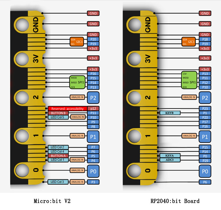
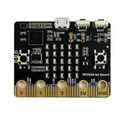
The RP2040:bit Board has 25 external connections on the edge connector of the board, which are referred to as ‘pins’. The edge connector is the gold area on the right side of board as shown the figure below.

| Pin | Description |
|---|---|
| 0 | KEYA |
| 1 | KEYB |
| 10 | GPIO that is conventionally used for the serial clock (SCK) signal of the 3-wire Serial Peripheral Interface (SPI) bus. |
| 11 | GPIO that is conventionally used for the Master Out Slave In (MOSI) signal of the SPI bus. |
| 12 | GPIO that is conventionally used for the Master In Slave Out (MISO) signal of the SPI bus. |
| 13 | CSn |
| 17 | These pins are wired to the 3V supply, like the large ‘3V’ pad. |
| 18,19 | Implement the clock signal (SCL) and data line (SDA) of the I2C bus communication protocol. With I2C, several devices can be connected on the same bus and send/read messages to and from the CPU. Internally, the accelerometer and the compass are connected to i2c. |
| 29 | ADC3 |


