- sales/support
Google Chat:---
- sales
+86-0755-88291180
- sales01
sales@spotpear.com
- sales02
dragon_manager@163.com
- support
tech-support@spotpear.com
- CEO-Complaints
zhoujie@spotpear.com
- sales/support
WhatsApp:13246739196
Raspberry Pi Stepper Motor HAT (B) User Guide
Features
- Raspberry Pi connectivity, compatible with Raspberry Pi Zero/Zero W/Zero WH/2B/3B/3B+
- Onboard dual DRV8825 motor controller IC with built-in microstepping indexer,easy to drive two stepper motors
- 6 available microstepping modes, configured with the DIP switches: full-step, half-step, 1/4-step, 1/8-step, 1/16-step, and 1/32-step
- Adjustable motor drive current via potentiometer, maximum 2.5A current output
- Integrates 5V regulator, allows providing power to Raspberry Pi
- Onboard multi connector options for stepper motors in different specifications
Parameter
- Motor controller: HR8825
- Motor drive voltage: 8.2V~28V
- Motor drive current: 2.5A
- Dimension: 65mm × 56mm
- Mounting hole size: 3.0mm
Onboard Resource
| Pin | Description |
|---|---|
| VCC | 8.2~28V Power Input |
| 5V | 5V Power |
| GND | Ground |
| A1 | Output 1 of bipolar stepper motor M1 winding A |
| A2 | Output 2 of bipolar stepper motor M1 winding A |
| B1 | Output 1 of bipolar stepper motor M1 winding B |
| B2 | Output 2 of bipolar stepper motor M1 winding B |
| A3 | Output 3 of bipolar stepper motor M2 winding A |
| A4 | Output 4 of bipolar stepper motor M2 winding A |
| B3 | Output 3 of bipolar stepper motor M2 winding B |
| B4 | Output 4 of bipolar stepper motor M2 winding B |
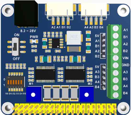
In which: A1、A2、B1、B2: Control pins of stepper motor M1; A3、A4、B3、B4: Control pins of stepper motor M2;
Power switch: Control power supply for Raspberry Pi; Switch D0-D5: Control subdivision format;
D0-D2: Control stepper motor 1;D3-D5: Control stepper motor 2;Potentiometers: Control output current
Power
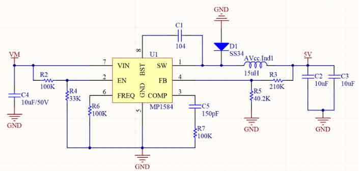
MP1584 regular supports 4.5V to 28V input, and up to 2A current output. Even though MP1584 supports the lowest input of 4.5V. However, VM also supplies power for the motor controller, which requires at least 8.2V. So, the recommended input voltage is 8.2~28v.
The specification of the power DC head is a powerhead with an outer diameter of 5.5 and an inner diameter of 2.1. There are many DC heads on the market with this specification. You can use a 9V2A or 12V2A power supply for power supply.
Motor Driver
HR8825 is a dual H-bridge motor driver chip that supports 32 subdivisions. It also integrates short-circuit, overheating, under-voltage and cross-conduction protection circuits, which can detect fault conditions and quickly cut off the H-bridge, thus providing protection for the motor and driver chip.
VM is the input voltage, the input range is: 8.2V to 45V, the input range of the integrated voltage regulator chip is 8.2V to 28V.
nSLEEP needs to be kept high, otherwise the chip will directly enter sleep mode, the H-bridge of the device is disabled, the charge pump circuit stops working, the V3P3 output is disabled, and all internal clocks stop working, and all logic inputs are ignored.
The nENBL pin is an enable pin, inputting a low level, the H bridge output is enabled, and the rising edge on STEP is recognized. When the input is high, the H-bridge is disabled, the output is in a high-impedance state, and the STEP input is ignored. It must be disabled when it is not working, otherwise the chip will remain in the enabled state, and the chip and the motor will always be in a high temperature state!
STEP is the stepping clock input, DIR is the direction control input, and MODE0, MODE1, and MODE2 are the subdivision inputs.
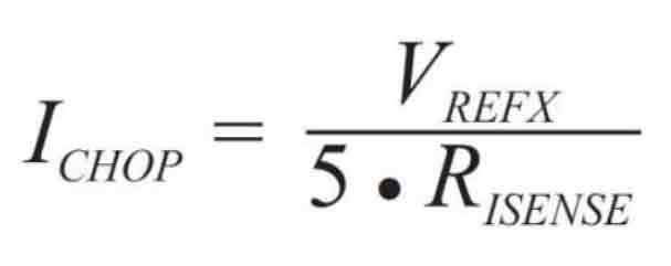
Pins 12 and 13 are used to adjust the output current, R13 and R16 are sampling resistors of 0.2 ohms, according to the formula on the data sheet (data sheet: page11):
Ichop = V(xREF)/(5*R(ISENSE))
Substitute R(ISENSE) = 0.2 into the formula
Then the output current is proportional to the voltage on the potentiometer:
I = Vref
If the torque of the motor is not enough, the output current can be increased by adjusting the on-board potentiometer.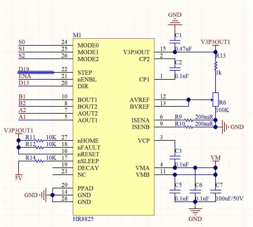
Control Protocol
HR8825 is a dual H-bridge motor driver chip. The H-bridge is a classic control motor circuit, named after its shape like the letter "H". It is composed of four triodes or mosfets, and the middle one is connected to the motor horizontally. To make the motor rotate, a group of diagonal lines needs to be turned on.
When Q1 and Q4 is accessed, the current flow from positive pole->Q1 to Q4->negative pole, then the motor moves forward.
When Q2 and Q4 is accessed, the current flow from the positive pole->Q2 to Q4->negative pole, then the motor moves backward.
If it is two H-bridge, there will be two set of output lines, for example, stepper motor has four wires which is two H-bridge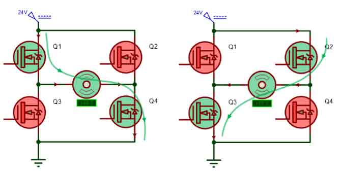
Protocol of Motor

According to Ampère's circuital law, when the current of coil A flow from left to right, the stator generates a magnetic field, internal side is the North pole which will adopt the rotator of the motor. When the currents of four coils are based on certain rules, they will generate a rotating magnetic field and drive the rotator rotates. If every motor has four rotators, it has four statuses:
Status 1: coil A left in right out(current), coil C right in left out, the motor rotates 0 degree;
Status 2: coil B top in bottom out, coil D bottom in top out, the motor rotates 90 degrees against status 1.
Status 3: coil A right in left out, coil C left in right out, the motor rotates 90 degrees against status 2;
Status 4: coil B bottom in top out, coil D top in left out, the motor rotates 90 degrees against status 3;
Motor turn from the previous status to the next status, we call it to step. The motor rotates in a circle every four steps, and its step angle is 90 degrees.
Most motors have more than four stators. For example, 42 motors, and 57 motors all have 50 stators with a step angle of 1.8 degrees.
28BYJ-48 is four-phase and eight steps, Speed Variation Ratio is 1/64 and its step angle is 5.625/64 degrees.
Microstepping
The rotation of the motor is due to the regular energization of the coil, which will synthesize a uniformly distributed circular rotating magnetic field, thereby attracting the rotor to rotate.
According to this principle, controlling the currents in the windings of each phase can make them rise or fall according to a certain law, that is, to form multiple stable intermediate current states between zero current and maximum current, the direction of the corresponding synthetic magnetic field vector is also There will be multiple stable intermediate states, and only the direction of this vector will be changed, so that the motor can rotate at a smaller angle and rotate more smoothly.
Taking the motor with the above four stators as an example, if it is subdivided into half, then it takes two steps to complete the transition from the first state to the second state, because the state after the first state, the A-coil 50% current, 50% of the current of the B coil will generate a vector magnetic field with an included angle of 45 degrees, thereby attracting the motor rotor to rotate 45 degrees. When running 8 steps, the motor completes one revolution.
HR8825
HR8825 only needs to give the number of pulses to realize the rotation of the stepper motor. According to the previous analysis, and without subdivision:
How many pulses are needed to drive 42 motors to make one revolution:
360 / 1.8 = 200
Through experiments, it was found that the 42 motors did rotate for a week
How many pulses are needed to drive the 28BYJ-48 motor to make one revolution:
360 / 5.625 * 64 = 4096
So are you sure that's the case? Through experiments, it was found that 28BYJ-48 turned for two weeks.
28BYJ-48 is a four-phase motor. It supports three working modes: single-four-beat, double-four-beat and eight-beat. The step angle of the eight-beat working mode is half of that of single-four-beat and double-four-beat. , is the single four-beat working method used, so it takes 2048 pulses to drive the 28BYJ-48 to make one revolution.
Setting
The module supports up to 32 microstepping and can be controlled using software or hardware.
- Software Microstepping Control:
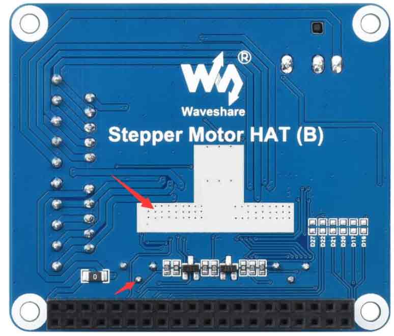
First, you need to solder the 6 resistors on the back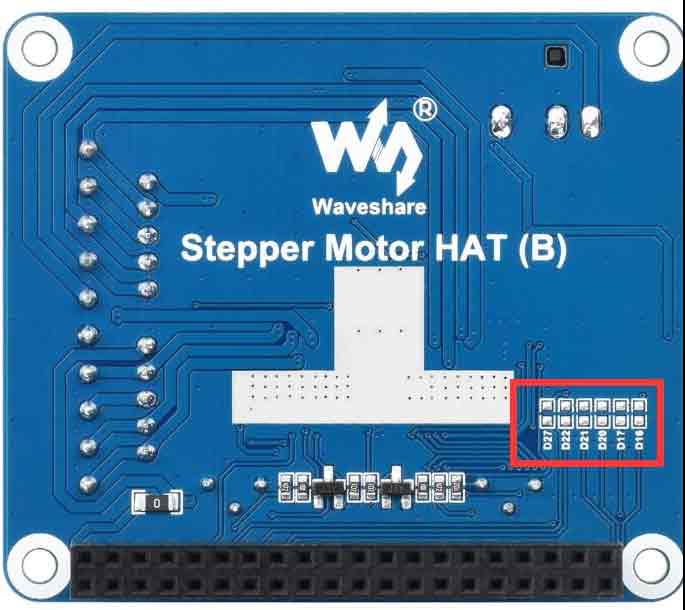
Modify the corresponding command on the program to enable the corresponding software system
python can be selected by 'softward'
c language can be selected by SOFTWARD
And it is necessary to turn all the DIP switches to 1 for the software control to take effect.
- Hardware Microstepping Control:
In the c program can be selected by HARDWARD
In python can be selected by 'hardward'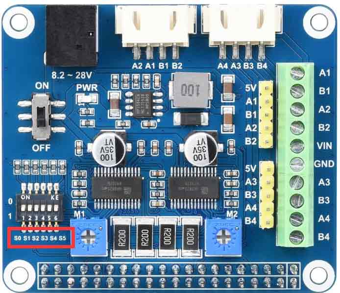
D0, D1, D2 correspond to MODE0, MODE1, MODE2 that control the M1 driver, and D3, D4, and D5 correspond to MODE0, MODE1, and MODE2 that control the M2 driver. The specific correspondence is as follows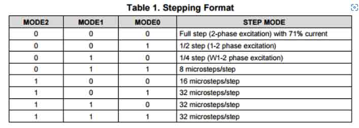
Note: The sample program needs to dial all D0-D5 to 0, corresponding to the full step.
Note: The default subdivision is all in the position of 1, so the subdivision of the hardware is very slow, and the experimental effect may not be seen. It is best to adjust it to 0.
Current Setting
The maximum output current of DRV8825 is 2.5A. The size of the current can be adjusted by adjusting the potentiometer in the figure below
Onboard Risense = 200mR, then we can simplify the formula: Ichop = Vxref
So Ichop is proportional to Vxref, Vxref is the voltage of the potentiometer, and Ichop is the output current.
When the potentiometer rotates clockwise, the voltage decreases, and when the potentiometer rotates counterclockwise, the voltage increases. If you need to measure, you can plug in the power supply to the module, use a multimeter, the red test lead touches the bottom, and the black test lead touches the upper rectangular pad.
The factory-set potentiometer is in the middle, which can drive most motors.
If the minimum phase current of the motor is larger than this, it may not reach the ideal state, and working for a long time may cause the chip to burn.
Do not turn it counterclockwise to the end. Working for a long time may cause the chip to burn.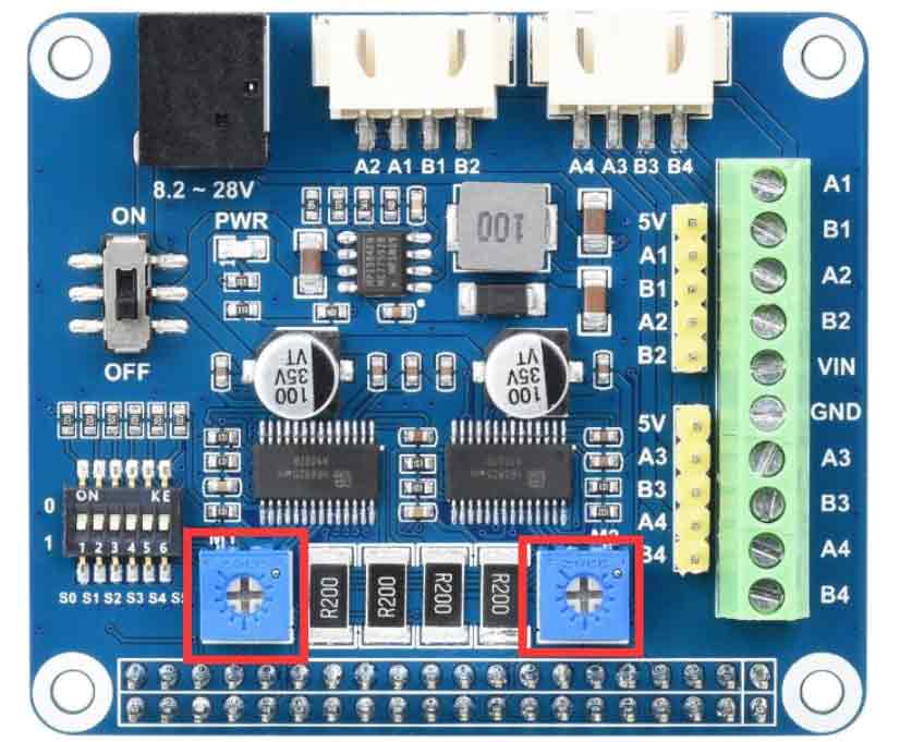
Raspberry Pi
Pin
| Stepper Motor HAT | Raspberry Pi (BCM) |
|---|---|
| A1A2B1B2 dir | 13 |
| A1A2B1B2 step | 19 |
| A1A2B1B2 enable | 12 |
| A1A2B1B2 mode | 16 17 20 |
| A3A4B3B4 dir | 24 |
| A3A4B3B4 step | 18 |
| A3A4B3B4 Dir | 4 |
| A3A4B3B4 mode | 21 22 27 |
Library Installation
BCM2835
#Enable the Raspberry Pi terminal and run the following command
wget http://www.airspayce.com/mikem/bcm2835/bcm2835-1.68.tar.gz
tar zxvf bcm2835-1.71.tar.gz
cd bcm2835-1.71/
sudo ./configure && sudo make && sudo make check && sudo make install
# For more information, please refer to the official website: http://www.airspayce.com/mikem/bcm2835/
WiringPi
#Open the Raspberry Pi terminal and run the following command
sudo apt-get install wiringpi
#For Raspberry Pi systems after May 2019 (earlier than before, you may not need to execute), you may need to upgrade:
wget https://project-downloads.drogon.net/wiringpi-latest.deb
sudo dpkg -i wiringpi-latest.deb
gpio -v
# Run gpio -v and version 2.52 will appear. If it does not appear, the installation is wrong

#Bullseye branch system use the following command:
git clone https://github.com/WiringPi/WiringPi
cd WiringPi
./build
gpio -v
# Run gpio -v and version 2.60 will appear. If it does not appear, it means that there is an installation error
Python
sudo apt-get update
sudo pip install RPi.GPIO
Download Sample Program
sudo apt-get install p7zip-full
wget https://www.waveshare.com/wiki/File:Stepper_Motor_HAT_B_Code.7z
7z x Stepper_Motor_HAT_Code_B.7z -r -o./Stepper_Motor_HAT_Code_B
sudo chmod 777 -R Stepper_Motor_HAT_Code_B
cd Stepper_Motor_HAT_Code_B/Raspberry\ PI/
Running Sample Program
Provide three programs, BCM2835, wiringPi, python
Do the following steps before running the program:
1. Raspberry Pi uses independent power supply
2. The DC port of the module is connected to 8.2V-28V power supply, and the switch is turned ON
3. Correctly connect the stepper motor
- BCM2835 Demo
cd bcm2835/
make clean
make
sudo ./motor
- wiringPi Demo
cd wiringpi/
make clean
make
sudo ./motor
- Python Demo
cd python/
sudo python test.py
Jetson Nano
Library Installation
#python2
sudo apt-get install python-pip
sudo pip install Jetson.GPIO
sudo groupadd -f -r gpio
sudo usermod -a -G gpio your_user_name
sudo udevadm control --reload-rules && sudo udevadm trigger
#python3
sudo apt-get install python3-pip
sudo pip3 install Jetson.GPIO
sudo groupadd -f -r gpio
sudo usermod -a -G gpio your_user_name
sudo udevadm control --reload-rules && sudo udevadm trigger
Download Sample Program
sudo apt-get install p7zip-full
wget https://www.waveshare.net/w/upload/9/9d/Stepper_Motor_HAT_B_Code.7z
7z x Stepper_Motor_HAT_Code_B.7z -r -o./Stepper_Motor_HAT_Code_B
sudo chmod 777 -R Stepper_Motor_HAT_Code_B
cd Stepper_Motor_HAT_Code_B/Jetson\ nano/
Running Sample Program
Provides three demos: C, Python2, Python3
- C
cd C/
make clean
make
sudo ./main
- Python 2
cd python2/
sudo python main.py
- Python 3
cd python3/
sudo python3 main.py


