


- sales/support
Google Chat:---
- sales
+86-0755-88291180
- sales01
sales@spotpear.com
- sales02
dragon_manager@163.com
- support
tech-support@spotpear.com
- CEO-Complaints
zhoujie@spotpear.com
- Only Tech-Support
WhatsApp:13246739196
- Purchase/Shipping/Refund
WhatsApp:13424403025
- HOME
- >
- ARTICLES
- >
- Common Moudle
- >
- ESP
T-Camera-S3-0.96inch User Guide
【Examples】
examples examples
├─AllFunction                       # Full function test
├─MinimalCameraExample              # Minimal camera example
├─MinimalPowersExample              # Minimal PMU operation example
├─MinimalScreenExample              # Minimal screen example
├─MinimalSoundDetectionExample      # Minimal ambient sound detection example
└─MinimalVoiceWakeupExample         # Minimal voice wakeup example
【Software】
- Installation VisualStudioCode and Python
- Search for PlatformIO plug-in in
VisualStudioCodeextension and install it. VisualStudioCodeneeds to be restarted after installation.- VisualStudioCode, select File in the upper left corner of VisualStudioCode-> Open Folder-> Select LilyGo-Cam-ESP32S3 directory.
- Click the platformio.ini file and cancel the sample lines to be used in the platformio column. Please ensure that only one line is valid.
- Click the (√) symbol in the lower left corner to compile.
- Connect the board to the computer USB.
- Click (→) to upload the firmware.
- Click (plug symbol) to monitor serial output.
- Use
AllFunctionandMinimalSoundDetectionExampleExample, need to upload additional model files, according to the following steps.- Click PlatformIO(bee icon) to the left of VisualStudioCode.
- Select
t-cameras3 - Select
Platform - After ensuring that the board is connected to USB, click
Upload Filesystem image
【Note】
- Can I use
Arduino IDE?AllFunctionandMinimalSoundDetectionExampleexample is not acceptable, because you need to upload model files and custom partition tables. At present, Arduino IDE does not support custom partition tables and uploading model files (the time for writing README is 20220930).- The remaining example is that Arduino IDE can be used.
- The board is integrated with PMU(Power management chip), which has short-circuit and overload protection. By default, PWRKEYneeds to press for 6 seconds to turn off the power supply of the board, and press PWRKEY for 128 milliseconds to turn on the power supply. If you need to modify the power-off pressing time, please refer to MinimalPowersExample.
- If the charging function is needed, the
PMUTS Pindetection function needs to be turned off. By default, there is no NTC sensor on board, so it is necessary to disable TS Pin detection in order to use the charging function normally. If the TS Pin detection function is not turned off, the PMU charging indicator light will blink after inserting the battery, and charging will be disabled at this time. - The external 5 Pin expansion socket of the board, 5V is shared with
PMUSYS, please do not externally connect an external power supply load larger than 600mA, and the 3.3V is powered by PMUDCDC3, and the voltage can be adjusted, and the maximum output current should not exceed 1A - All peripherals on board except OLED can turn off the power supply.
- When the sketch cannot be uploaded, please press and hold the BOOT button on the board, and then insert USB. At this time, you should be able to see the port in the device manager of the computer, and then click Upload Sketch again.
- When the power channel of ESP32S3 is turned off by mistake, please insert USB, then press and hold the BOOT button of the board, and then press and hold the PWRKEY button. At this time, the board enters the download mode, and the sketch can be uploaded normally.
- Please understand the risks before changing the peripheral voltage, otherwise, please do not try to change the voltage of the camera and other onboard equipment, which may cause permanent damage.
- When you think there is something wrong with the board, you can try to burn our factory firmware for testing, and you can rule out whether it is a hardware problem first. FactoryFirmware
【Pins】
Camera
| PWDN | Reset | XCLK | SDA | SCL | VSYNC | HREF | PCLK |
|---|---|---|---|---|---|---|---|
| N/A | 39 | 38 | 5 | 4 | 8 | 18 | 12 |
| D9 | D8 | D7 | D6 | D5 | D4 | D3 | D2 |
| 9 | 10 | 11 | 13 | 21 | 48 | 47 | 14 |
| OLED/PMU/PIR | SDA | SCL | PMU IRQ | PIR |
|---|---|---|---|---|
| 7 | 6 | 2 | 17 | |
| Microphone | WS | DATA | CLK | |
| 42 | 41 | 40 |
Power Channel:
| PMU Channel | Microphone | OLED | Camera | Pir |
|---|---|---|---|---|
| BLDO1 | DCDC1 | ALDO1/ALDO2/ALDO4 | ALDO3 |
TAG:
14 inch Dual LCD Computer PC Monitor Display Double Secondary Screen Type C Mini HDMI 1080P For Windows/MacOS
ESP32 C6 Development Board 1.43 inch AMOLED QSPI Display 1.43inch TouchScreen Dual MIC AudioI Deepseek N16R8
D-Robotics RDK X3 Module Core MD Module Horizon Sunrise Pi ARM Cortex-A53 5Tops Size Compatible With Raspberry Pi CM4 Size
Jetson Orin 4G/3G/2G expansion board GNSS GPS SIM7600G-H-M.2
Raspberry Pi OpenWrt Tutorial 1
Wiki
Horizontal Drag Instructions
IR Thermal Imaging Camera
Raspberry Pi MIPI
Raspberry Pi CM4
Raspberry Pi 5inch Display 1024x600 HDMI Capacitive TouchScreen 5 inch LCD B Wide-Cover For Mini PC
Raspberry Pi Pico 2 Tiny RP2350B RP2350-Linux Mini Development Board with PSRAM-8MB Or Without PSRAM
RS485 to RJ45
RV1103 SC3336
Raspberry Pi 5 PD Power
Gyroscope
Raspberry Pi DSI 800×480
Milk-V
spotpear
ESP32 C3 1.44inch LCD
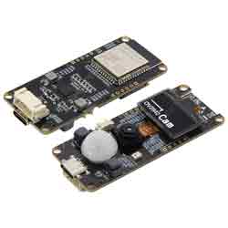
ESP32 S3 Development board T Camera S3 With 0.96inch OLED display screen OV2640Camera WiFi Bluetooth
TAG:
ESP32 C3 Round LCD Electronic EYE 0.71 inch Display Watch Screen GC9D01 160x160
Pi5 Active Cooler
Serial UART Magnetic Encoder Bus Servo TTL ST3235 30KG.CM High Precision Large Torque
SpotPear
Raspberry Pi 5 inch DSI IPS LCD Display MIPI 800x480 Optional Touchscreen
5.79inch e Paper Ink (G) Red-Yellow-Black-White display 792x272 Arduino Raspberry Pi Jetson STM32
LCD Screen
Raspberry Pi LCD display screen 1.3inch ST7789 with
Raspber Pi 5 PD Power
Providing Effective Interference Shielding
VGA to RGB
Raspberry Pi Autofocus Camera 12MP IMX708 120° FOV
Raspberry Pi 4 Model B
Raspberry Pi 5 Argon NEO 5 M.2 NVME PCIE Case Pi5
240x280
Arduino 1.5inch LCD
1.54 inch Passive NFC e-Paper ink (G) RYBW Display Screen No Need Battery Wireless Power & Data Transfer
Raspberry Pi PICO LoRa
WiFi Wireless ESP32 DDSM Motor Driver Direct Drive Servo Hub Motors Raspberry Pi
Raspberry Pi CM5 Industrial Module 4G/5G/LoRa Gigabit Ethernet RJ45