- sales/support
Google Chat:---
- sales
+86-0755-88291180
- sales01
sales@spotpear.com
- sales02
dragon_manager@163.com
- support
tech-support@spotpear.com
- CEO-Complaints
zhoujie@spotpear.com
- Only Tech-Support
WhatsApp:13246739196
- Purchase/Shipping/Refund
WhatsApp:13424403025
- HOME
- >
- ARTICLES
- >
- Common Moudle
- >
- UART Module
CAN FD TO ETH User Guide
Overview
Introduction
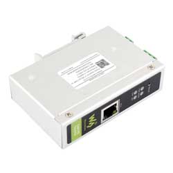
The CAN FD TO ETH is a DIN-rail CAN FD to ETH bidirectional converter, featuring high-speed, low-latency, stable performance, ease of use, and cost-effectiveness. It supports five data conversion modes: transparent conversion, transparent conversion with ID, standard protocol conversion, Modbus protocol conversion, and custom protocol conversion. It enables interconnection between CAN and Network port devices, compatible with CAN FD and CAN 2.0A/2.0B protocols.
It features industrial-grade design, supports -40°C ~ 85°C stable working, 9V ~ 36V wide power input, 5Kbps~1Mbps CAN FD arbitration domain baud rate, and 100Kbps~5Mbps CAN FD data domain baud rate.
It supports parameter configuration via host computer, built-in 120Ω terminal resistors (switchable via DIP switches), supports DIN-rail mounting, easy to configure and install.
Specifications
| Classification | Parameter | Value |
|---|---|---|
| Basic parameters | Working voltage | DC 9V ~ 36V |
| Size | 110 × 27 × 76.1 (mm) | |
| Installation | DIN-rail installation | |
| Reload button | Long press to restore factory settings | |
| Indicator light | POWER, WORK, NET and CAN | |
| Interface parameters | CAN port specification | 1-ch CAN port, supports CAN FD, compatible with CAN 2.0A/2.0B |
| CAN port baud rate | Arbitration domain baud rate: 5Kbps ~ 1Mbps Data domain baud rate: 100Kbps ~ 5Mbps | |
| Terminal resistor | Built-in 2 × 120Ω terminal resistors Switching either DIP switch to ON connects one 120 Ω resistor in parallel | |
| Network port specification | RJ45, 10/100Mbps, cross-connection adaptive | |
| Working Environment | Working temperature | -40℃ ~ 85℃ |
| Storage temperature | -40℃ ~ 105℃ | |
| Working humidity | 5% ~ 95% RH (no condensation) | |
| Storage humidity | 5% ~ 95% RH (no condensation) | |
| Software function | Networking protocol | TCP server, TCP client, UDP server, and UDP client |
| Modbus gateway | CAN FD to Modbus TCP (Master/Slave) | |
| Send message | Supports up to 64 transmit messages | |
| Receive message | Supports up to 64 receiving messages | |
| Protocol conversion | Transparent conversion, transparent conversion with ID, standard protocol conversion, Modbus protocol conversion, and custom protocol conversion | |
| CAN ID | Supports standard frame and extended frame | |
| Frame ID filtering | Supports only standard frames, only extended frames, and custom input frame ID (up to 32 groups) | |
| Pack frame time | Supports customizing the number of frames and the time of frame packing | |
| Change direction | Supports bidirectional conversion, only Network port to CAN, and only CAN to Network port | |
| Firmware upgrade | Supports the host computer for firmware upgrade | |
| Parameter configuration | AT command and host computer software configuration | |
| Other features | Supports heartbeat packets; register packets; normal, loopback, and only listen modes | |
| Protection parameters | ESD protection | Air discharge: 8 KV, Contact discharge: 6 KV |
| Eft/Burst | Power circuit: 2KV; Network port & CAN port circuit: 1KV | |
| Surge immunity test | Power circuit: 1kV differential mode, 2kV common mode; CAN port circuit: 2kV common mode; Network port circuit: 2kV |
Hardware Description
Indicator Light Description
| Indicator | Color | Function description |
| POWER light | Red | Always on when powered on, turns off when powered off |
| STA light | Green | Flickering: Device operating normally, frequency 1s; Strobe: Enters the CAN bus passive error state; Always on: CAN bus running abnormally |
| NET light | Green/Red | Green flickering: Indicates that the network port is receiving data Red flickering: Indicates that data is being sent from the network port |
| CAN light | Red | Green flickering: Indicates that the CAN port is receiving data Red flickering: Indicates that data is being sent from the CAN port |
Software Operation
- Note: Take the transmission mode as an example
CAN FD Converter Basic Parameter Configuration
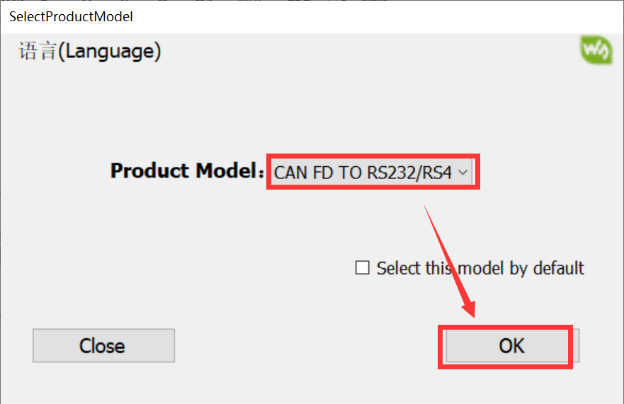
- Open WS-CAN-FD-Converter and select CAN FD TO ETH. (The software defaults to English and can be modified to Chinese)
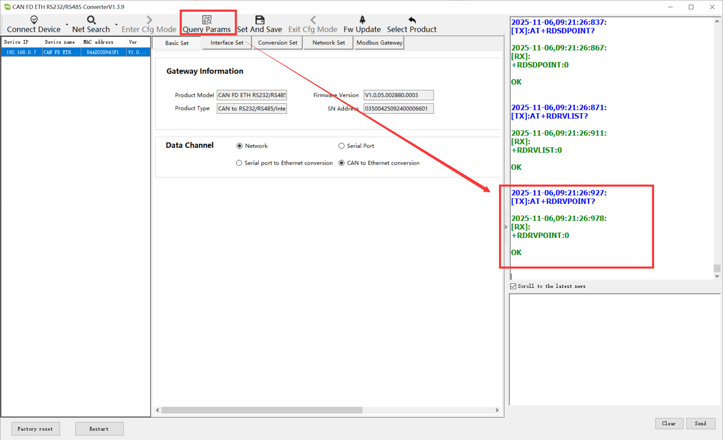
- Click on Net Search, target device, and Read Params in order.
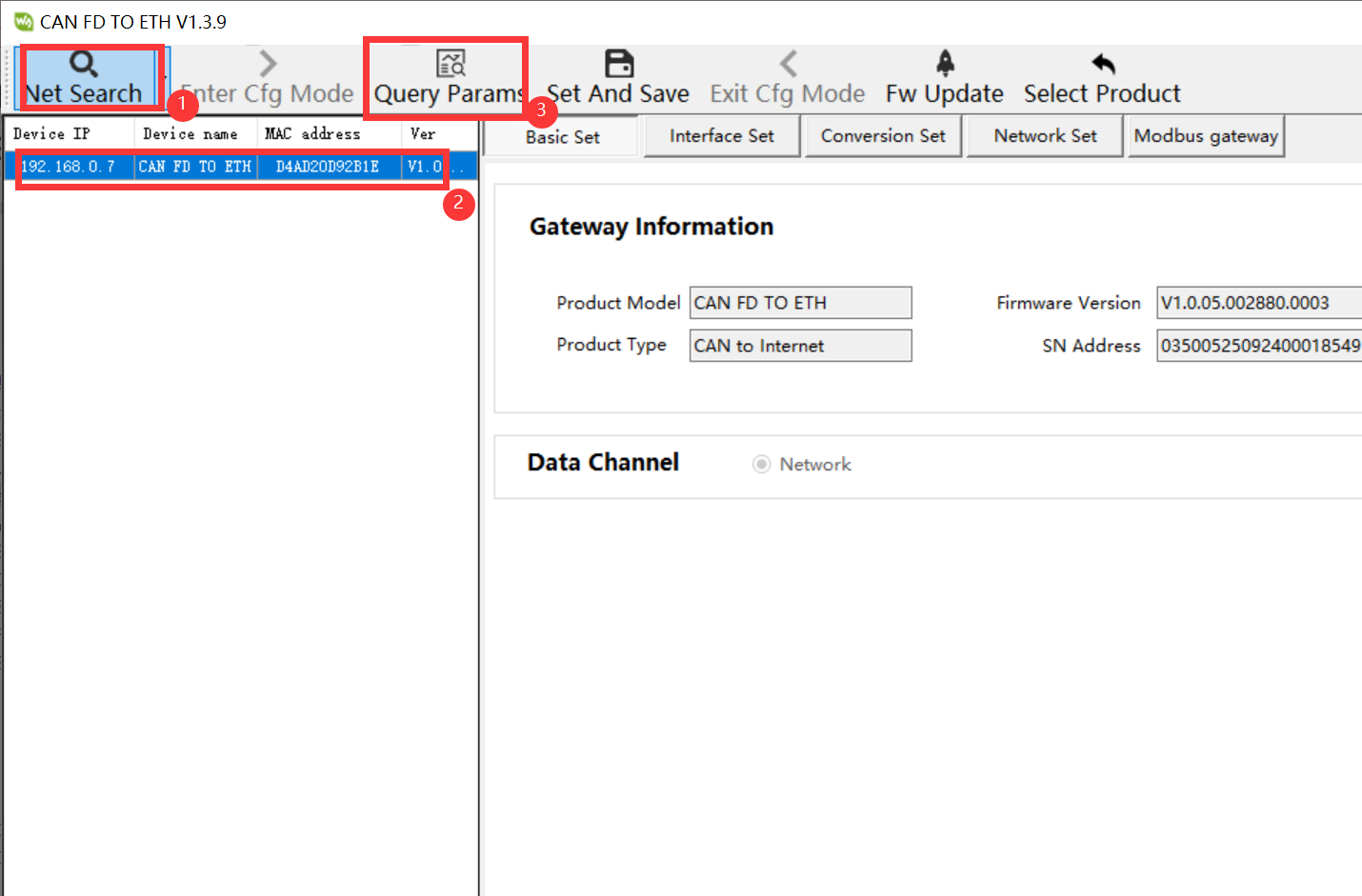
- If there is an error prompt in the message bar on the right, click "Read Params" again until no error occurs before proceeding to the next step
- Click Interface Set, set CANFD mode, enable CANFD Accelerate, Arbitration domain baud rate as 1000k, Data domain baud rate as 5000k, and then click Network Set
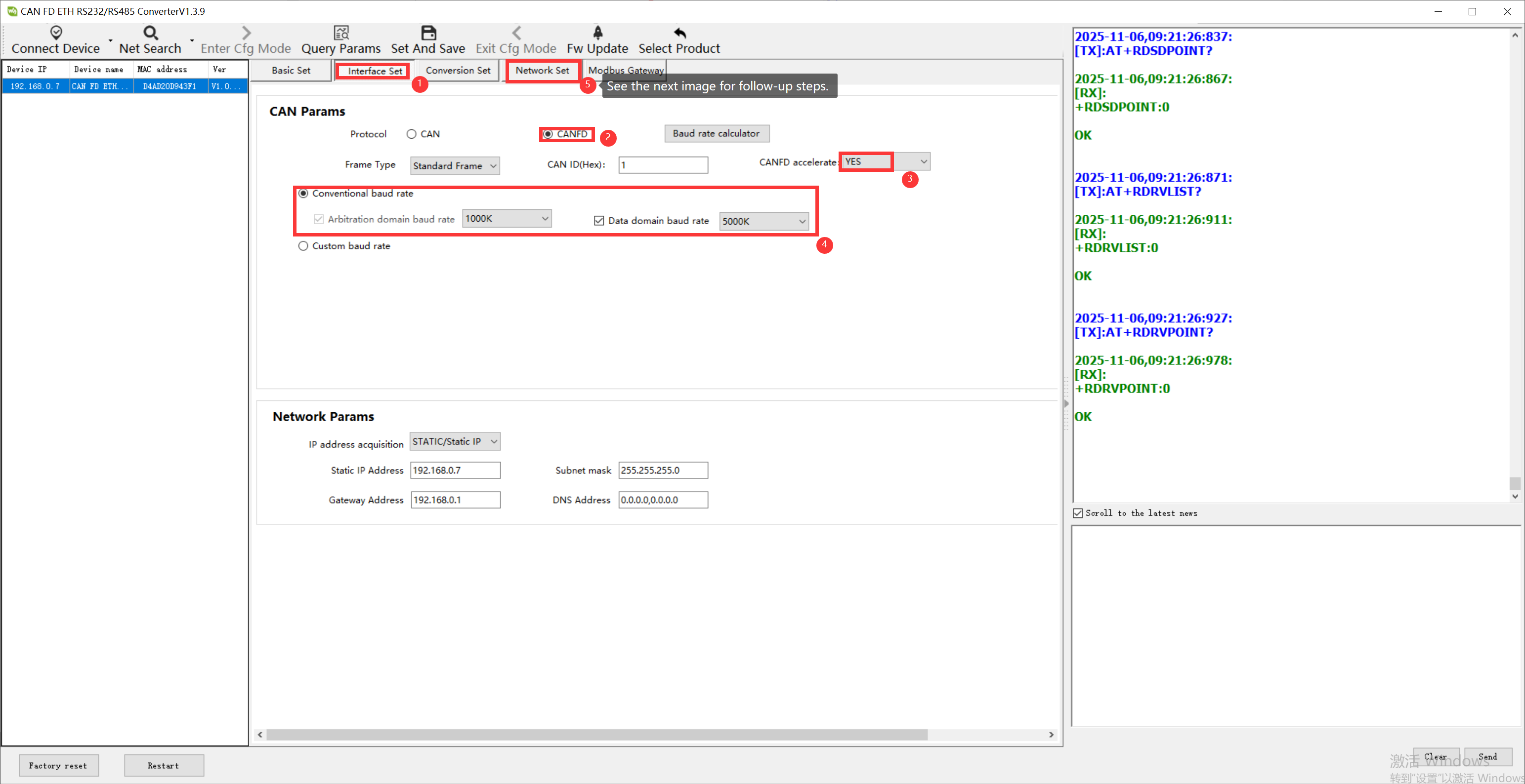
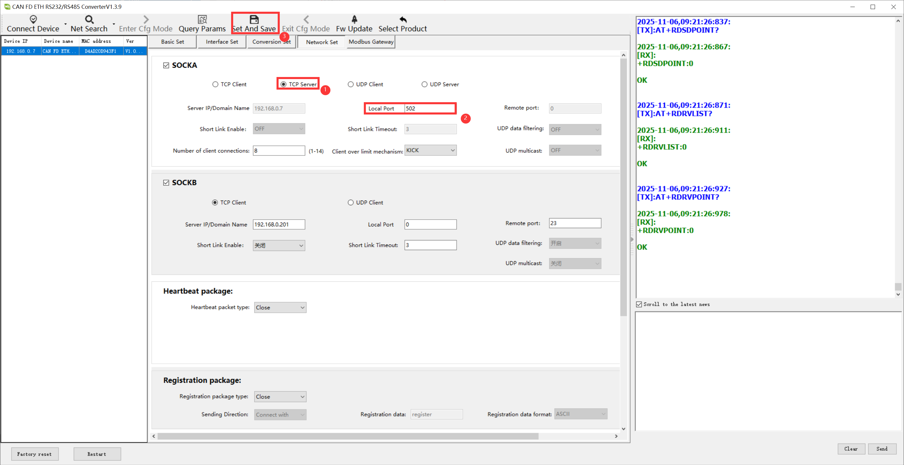
- Select TCP Server in network working mode, change the local port to 502, and finally click Set and Save to end the device configuration. The command on the right has an error and needs to be saved or reconfigured
Example Demonstration
Connection Description
CAN
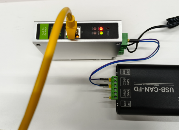
1. The CAN-H of CAN FD TO ETH is connected to the CAN1-H of USB-CAN-FD
2. The CAN-L of CAN FD TO ETH is connected to the CAN1-L of USB-CAN-FD
Network cable
The network port of CAN FD TO ETH is connected to the network port of the computer
USB_CANFD TOOL Communication Software Configuration
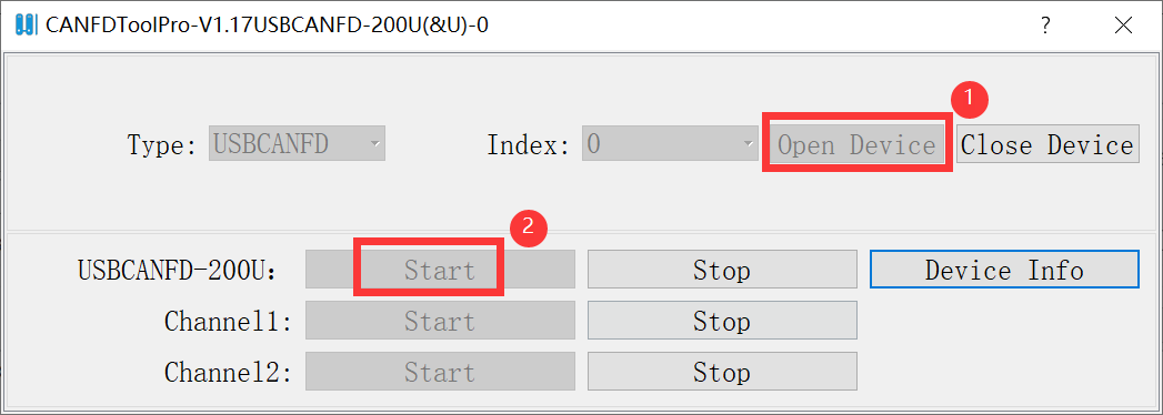
- Open the test software "USB_CANFD TOOL.exe" and click Device Operations
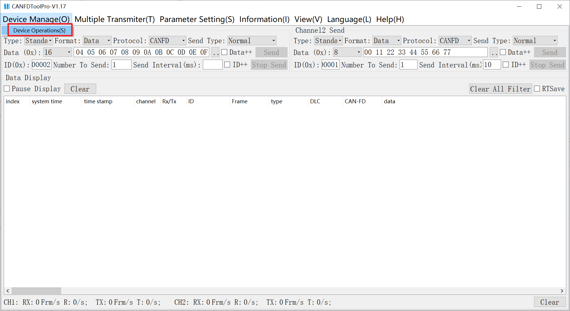
- Click "Open Device" next to the Index, then click "Start" next to USBCANFD- 200U
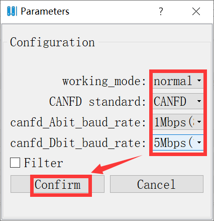
- Select "Normal" for working mode, "CANFD ISO" for CANFD standard, "1Mbps" for arbitration domain baud rate, "5Mbps" for data domain baud rate, and finally click "Conform"
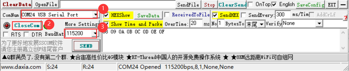
SSCOM Software Settings
- Select TCPClient mode in the network settings area, enter the remote IP address as 192.168.0.7, which is the module's default IP address, select the local IP address as 192.168.0.200 (choose according to the specific situation), server port 502, which is the module's TCP port, and click to establish a TCP connection.
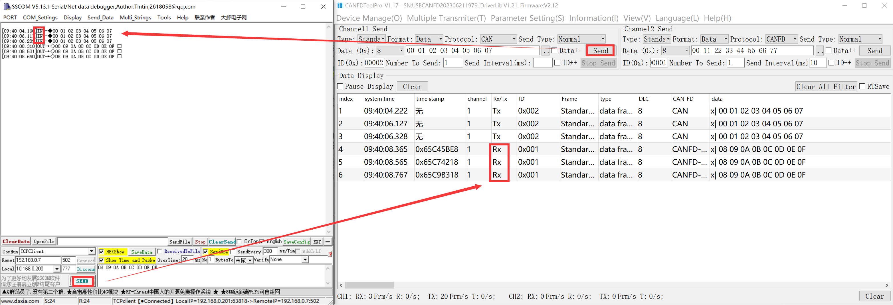
Interface Transmission and Reception Communication Test
- USB_CANFD TOOL: Click to send message, send data 55 55 66 66 77 77 88 88. SSCOM software: Check HEX hexadecimal to receive data 55 55 66 66 77 77 88 88.
- SSCOM software: Click to send message, send data 11 11 22 22 33 33 44 44. USB_CANFD TOOL: Check HEX hexadecimal to receive data 11 11 22 22 33 33 44 44.
Instructions for Conversion Modes
Transparent Conversion
- In the transparent conversion mode, the data received from one bus is immediately converted and sent to the other bus, without attaching data or making any modifications to the data. This not only realizes the exchange of data formats without changing the data content, and the converter is transparent to the buses at both ends.
- The CAN message frame information (frame type part) and frame ID are pre-configured by the user and remain unchanged during the conversion process. The user can choose whether to convert the frame information and frame ID.
- This method does not increase the communication burden on users, but can convert data in real-time and handle the transmission of large amounts of data.
Ethernet to CAN(FD)
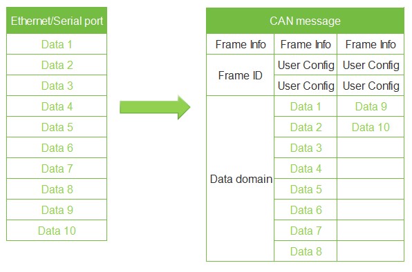
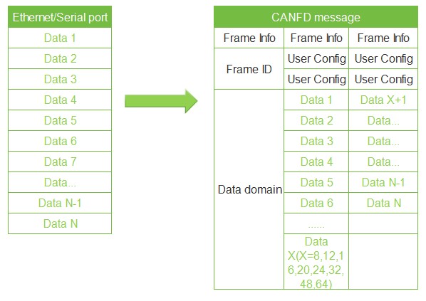
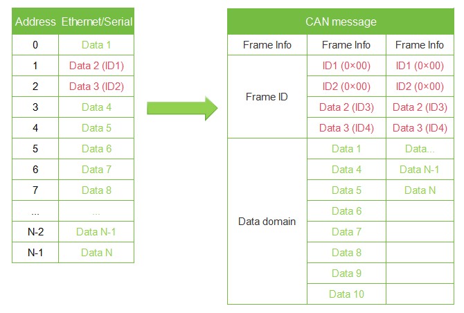
- Ethernet frame to CAN message: All data from Ethernet frames is sequentially filled into the data field of CAN message frame. As soon as the converter detects data on the Ethernet, it immediately receives and converts it. The frame information (frame type section) and frame ID need to be pre-configured.
- CAN mode: Maximum 8 bytes per frame of data.
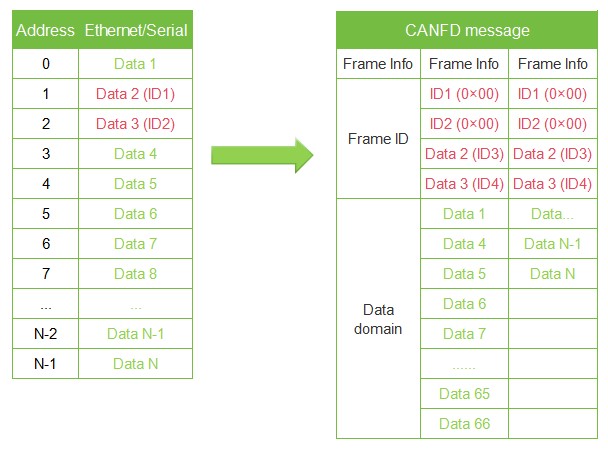
- CANFD mode: Maximum 64 bytes per frame of data. Note: When the data length exceeds 8 bytes, it must be encoded according to the length of CANFD's DLC to ensure accurate conversion, i.e., the length is 12, 16, 20, 24, 32, 48, 64, otherwise the converter will automatically split the CANFD messages into several CANFD messages of appropriate length.
- ETH to CAN
- ETH to CAN FD
- ETH to CAN FD
CAN (FD) to Ethernet
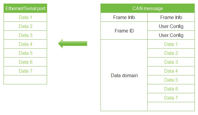
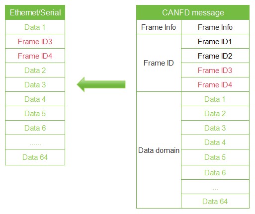
- Similarly, for CAN bus messages, one received CAN(FD) message will be immediately forwarded.
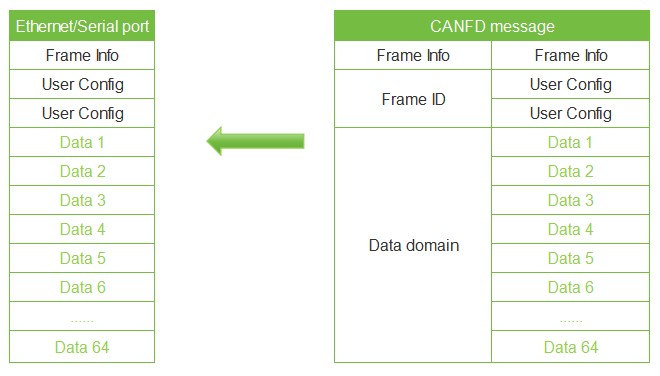
- If the configuration enables frame information, the converter will add the frame information of the CAN (FD) message to the first byte of the Ethernet frame during operation. Frame information for CAN(FD) is not converted when unchecked.
- If the configuration enables the frame ID, the converter will add the frame ID of the CAN (FD) message before the frame data of the Ethernet frame and after the frame information (such as enabling the frame information) during operation
CAN to Ethernet data (enable frame information/enable frame ID not enabled) CANFD to Ethernet data (enable frame information/enable frame ID enabled)
- CAN to ETH (enable frame information/enable frame ID not enabled)
- CAN to ETH (enable frame information/enable frame ID not enabled)
- CAN FD to ETH (enable frame information/enable frame ID enabled)
- CAN FD to ETH (enable frame information/enable frame ID enabled)
Conversion Examples
Network port: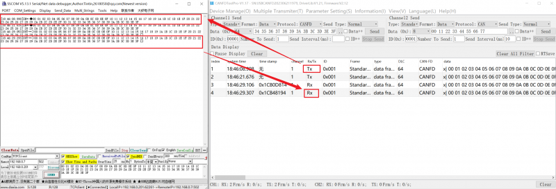
Transparent Conversion with ID
- Transparent conversion with ID is a special use of transparent conversion and does not add any protocol. This method can convert the "Address" in Ethernet data into the ID field of CAN (FD) messages, where the starting position and length of the frame ID in Ethernet data can be configured. The converter will extract this frame ID during conversion and fill it in the frame ID field of the CAN (FD) message as the ID of the CAN (FD) message when forwarding Ethernet data. Similarly, when CAN messages are converted to Ethernet data, the CAN(FD) message ID is also converted to the corresponding position in the Ethernet data.
- In this way, the converter adapts to the user's custom protocol to the maximum.
- Note: In this conversion mode, the "CAN ID" setting option of the configuration software is invalid because the identifier (frame ID) sent at this time is filled with data from the above Ethernet data.
Ethernet to CAN(FD)
- Configure the starting address and length of the "Frame ID" for CAN (FD) frame types and all CAN (FD) messages carried in Ethernet data. The range of the starting address is 0~7; the length range is standard frame: 1~2, and the extended frame: 1~4.
- The "Frame ID" of the CAN(FD) messages in the Ethernet data will be converted according to the pre-configured settings and mapped to the Frame ID field of the CAN(FD). If the length of the configured transparent conversion with ID is less than the frame ID length of the frame type in the CAN(FD) message, the high byte of the frame ID in the CAN(FD) message is padded with 0.
- For CAN (FD) messages, one frame is immediately forwarded upon receipt. During each forwarding, the ID in the received CAN (FD) message is converted based on the pre configured position and length of the CAN (FD) frame ID in the Ethernet data. Other data is forwarded in sequence.
- Note: If the CAN(FD) frame ID length is greater than the set transparent conversion with ID length, only the low bytes are taken and converted to the corresponding position in the Ethernet frame. For example: If the CAN frame ID is 01020304 and the transparent conversion with ID length is set to 2, then only 0304 is converted to the corresponding position in the Ethernet frame.
- ETH to CAN
- ETH to CAN
- ETH to CAN FD
- ETH to CAN FD
CAN (FD) to Ethernet
- For CAN (FD) messages, one frame is immediately forwarded upon receipt. During each forwarding, the ID in the received CAN (FD) message is converted based on the pre configured position and length of the CAN (FD) frame ID in the Ethernet data. Other data is forwarded in sequence.
- Note: If the CAN(FD) frame ID length is greater than the set transparent conversion with ID length, only the low bytes are taken and converted to the corresponding position in the Ethernet frame. For example: If the CAN frame ID is 01020304 and the transparent conversion with ID length is set to 2, then only 0304 is converted to the corresponding position in the Ethernet frame.
- CAN to ETH
- CAN to ETH

- CAN FD to ETH
- CAN FD to ETH
Conversion Examples
Network port: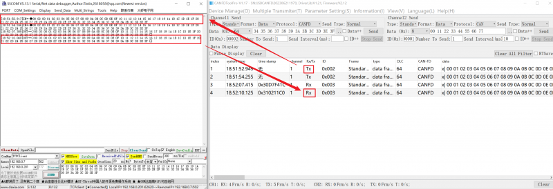
Standard Protocol Conversion
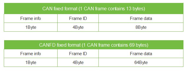
- Standard CAN frame format, each CAN frame contains 13 bytes, including CAN frame information (1 byte) + frame ID (4 bytes) + data frame (8 bytes).
- Standard CANFD frame format, each CANFD frame contains 69 bytes, including CANFD frame information (1 byte) + frame ID (4 bytes) + data frame (64 bytes).
- By correctly configuring the frame information (the first byte of data), it is possible to flexibly transmit standard, extended and even remote frames. Details of standard frames, extended frames, or remote frames can be obtained by correctly parsing Ethernet frames.
- Note:
- (1) In this conversion mode, the "CAN ID" and "Frame Type" configured in the software are invalid because the frame ID sent at this time is populated by the frame ID data in the Ethernet frame above, and the frame type is determined by the frame information in the Ethernet frame.
- (2) In this mode, the standard Ethernet data format must be strictly followed to successfully convert. It is necessary to ensure that the frame information is correct and that the reserved bits are zero. CAN frames have a fixed length of 13 bytes, CANFD frames have a fixed length of 69 bytes. If the length is not sufficient, it must be padded with 0s, otherwise it cannot be transmitted.
Standard CAN Frame Format
Frame information: 1 byte in length, used to identify frame information: frame type, frame length.
FF:  The identification bit for standard frame and extended frame, 1 for extended frame, 0 for standard frame.

RTR: The identification bit for remote frame and data frame, 1 for remote frame, 0 for data frame, and can only be 0 in CANFD mode.

EDL: CAN and CANFD identification, 0 for CAN, 1 for CANFD.

BRS: Baud rate switches enable identification, 0 for no rate conversion, 1 for variable rate conversion, valid only when CANFD. This bit should be 0 when CAN.

DLC3~DLC0: Data length bit, identifying the data length of the CAN(FD) frame.
Frame ID: 4 bytes long; high byte first, low byte last. The standard frame has 11 valid bits, and the extended frame has 29 valid bits.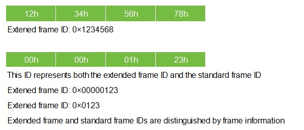
Frame data: In CAN mode, the length is 8 bytes, and in CANFD mode, the length is 64 bytes; if insufficient, it must be padded with 00.
Conversion Examples
Network port: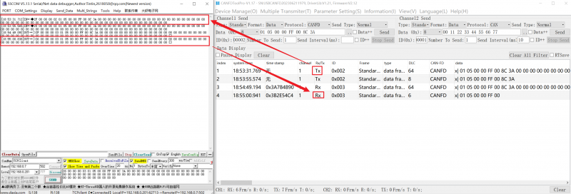
Modbus Protocol Conversion
The Modbus protocol conversion can convert the standard Modbus data protocol into a specific CAN(FD) data format. This conversion generally requires the CAN(FD) bus device messages to be editable.
On the CAN side, a simple and user-friendly segmented communication format has been developed to implement Modbus communication. The role of the converter remains protocol validation and forwarding. It supports the transmission of Modbus protocol, instead of the host or slave of Modbus, and the user can communicate according to the Modbus protocol.
Note:
(1) In this conversion mode, the "CAN ID" of the "CAN Parameter" item of the configuration software is invalid because the frame ID sent at this time is populated by the address field in the Modbus TCP Ethernet frame.
Frame Format
Modbus frame format:
Network port: Modbus TCP protocol, user frames must comply with this protocol.
CAN frame:
A segmentation protocol format is designed on the CAN side, which defines a segmentation and reorganization method, as shown below. Among them, the CAN frame information (remote frame or data frame; standard frame or extended frame) is set through configuration software.
In CAN mode, the transmitted Modbus protocol content can start from the "Data 2" byte. If the protocol content is greater than 7 bytes, then the remaining protocol content will continue to be converted according to this segmented format until the conversion is completed.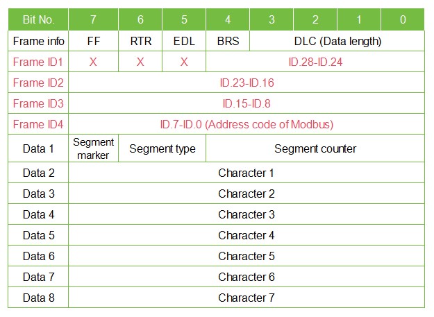
In CANFD mode, the transmitted Modbus protocol content can start from the "Data 2" byte. If the protocol content is greater than 63 bytes, then the remaining protocol content will continue to be converted according to this segmented format until the conversion is completed.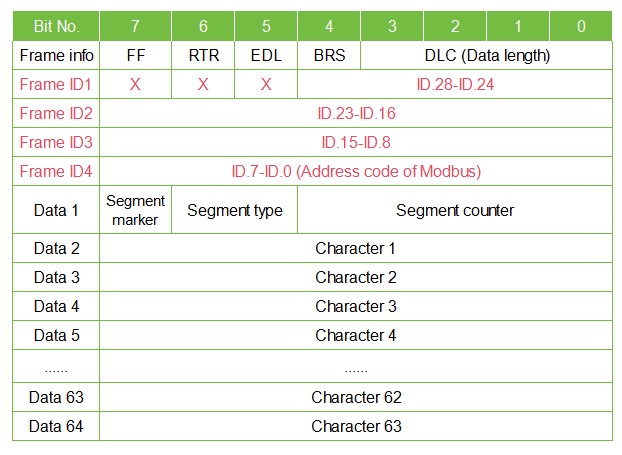
Data 1 is the segment control information (1 byte, 8 bits), which means the following:
- Segment mark: Occupies 1 bit (Bit7), indicating whether this message is a segmented message. This bit is 0 to indicate a standalone message, and 1 to indicate a frame belonging to a segmented message.
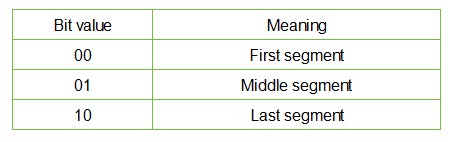
- Segment type: Occupies 2 bits (Bit6, Bit5), used to indicate the type of this message in segmented messages:
- Segment counter: Occupies 5 bits (Bit4~Bit0), indicating the sequence number of the segment in the entire message. If it is the nth segment, then the value of the counter is n. This allows you to verify that any segments are missing at the time of receipt.
Modbus TCP to CAN(FD)
The address field of the Modbus protocol is converted into the ID4 (extended frame) or ID2 (standard frame) of the frame ID in the CAN message, and the identifier remains unchanged during the conversion of this frame.
The MBAP header is not converted into a CAN message, and CAN messages do not have to have an MBAP header.
The conversion involves the Modbus protocol content—function code and data field—where they are sequentially converted into the data field of a CAN message frame (starting from the second data byte, with the first data byte used for segmented protocol). Since the length of Modbus frame varies depending on the function code, while a CAN message frame can only transmit 7 data, and a CANFD message frame can only transmit 63 data. Therefore, the converter will convert the longer Modbus frame segments into CAN messages and send them using the CAN fragmentation protocol described above. Users can process the function code and data field when receiving them on the CAN node.
CAN(FD) to Modbus TCP
For Modbus protocol data on the CAN bus, there is no need to perform cyclic redundancy check (CRC16). The converter receives it according to the segmentation protocol and automatically adds cyclic redundancy check (CRC16) after parsing one frame, then convert it into a Modbus frame and send it to the Ethernet bus.
Note: If the received data does not comply with the segmentation protocol, discard this group of data without conversion.
CAN: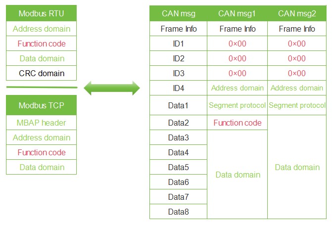
CAN FD: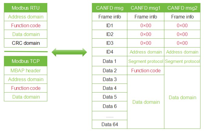
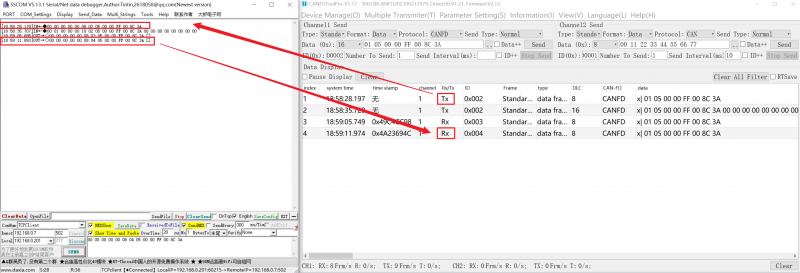
Conversion Examples
Network port:
Custom Protocol Conversion
To make it convenient for users to use CAN-bus, the Ethernet frame format is aligned with the CAN frame format. In the Ethernet frame, the start and end of a frame are specified, namely the "frame header" and "frame footer", which can be configured by the user.
Ethernet to CAN(FD)
The Ethernet frame format must comply with the specified frame format, otherwise it cannot be transmitted correctly. An Ethernet frame must contain: header, data length, data field, and frame footer. The frame header and footer are customized by the user and consist of 1 byte.
Data length refers to the byte length of a data field. The data length and frame end data must match to be transmitted correctly, otherwise they are discarded. For example, the frame header is configured as AA and the frame footer is configured as FF. For Ethernet frame AA03010204FF, it can be transmitted normally. If the Ethernet frame AA0301020304FF is to be sent, and the data field 010203 is followed by 04 instead of the frame footer FF, the frame is discarded and cannot be transmitted.
As with transparent conversion, the CANID and CAN types need to be configured by yourself in custom protocol conversion. The frame header, frame footer, and data length are not converted into CAN frames.
CAN: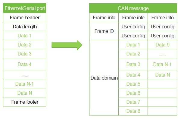
CAN FD: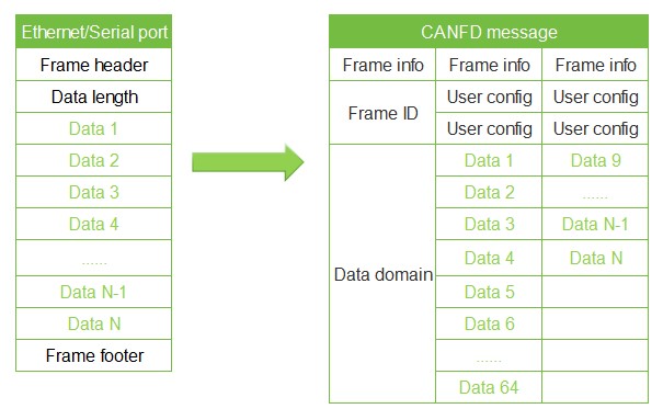
Ethernet to CAN(FD)
The CAN(FD) bus message forwards one frame for every frame received. The module will sequentially convert the data in the CAN message data field, while automatically adding frame header, frame length, frame information, and other data to the Ethernet frame. This is essentially the reverse form of converting an Ethernet frame to a CAN message.
CAN: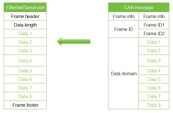
CAN FD: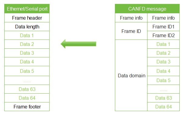
Conversion Examples
Network port: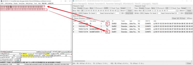
Resources
Software
FAQ
Support
Monday-Friday (9:30-6:30) Saturday (9:30-5:30)
Email: services01@spotpear.com