- sales/support
Google Chat:---
- sales
+86-0755-88291180
- sales01
sales@spotpear.com
- sales02
dragon_manager@163.com
- support
tech-support@spotpear.com
- CEO-Complaints
zhoujie@spotpear.com
- Only Tech-Support
WhatsApp:13246739196
- Purchase/Shipping/Refund
WhatsApp:13424403025
- HOME
- >
- ARTICLES
- >
- Common Moudle
- >
- UART Module
USB TO RS485/422 User Guide
Introduction
USB TO RS485/422, an industrial-grade USB to RS485/422 isolated converter, adopts the original FT232RNL, an industrial rail case design, built-in protection circuits such as power isolation, ADI magnetic coupling isolation, and TVS. USB TO RS485/422 is easy to operate, and can automatically transmit and receive without delay. It features fast communication speed, stability, reliability, and safety, which can be applied to various industrial control devices or applications with high communication requirements.
Features
- Onboard Original FT232RL and SP485EEN chip. Fast communication, stable and reliable, better compatibility.
- Onboard unibody power supply isolation, provides stable isolated voltage and needs no extra power supply for the isolated terminal.
- Onboard unibody digital isolation, allows signal isolation, high reliability, strong anti-interference, and low power consumption.
- Onboard TVS (Transient Voltage Suppressor), effectively suppresses surge voltage and transient spike voltage in the circuit, lightning-proof & anti-electrostatic.
- Onboard self-recovery fuse and protection diodes, ensure the current/voltage stable outputs, provide over-current/over-voltage proof, improve shock resistance.
- Onboard 15KV ESD isolation protection and 600W lightning-proof & anti-surge protection.
- Onboard 120R terminal resistor on the RS485/RS422 ports, enable by default, configurable by jumper.
- 3x LEDs for indicating the power and transceiver status.
- Industrial rail-mount ABS case design, small in size, easy to install, and cost-effective
Specification
| Model | Industrial grade isolated USB to RS485/422 converter | |
| Baud Rate | FT232RNL | 300bps ~ 3Mbps |
| Host Port | USB | |
| Device Port | RS485/422 | |
| USB Port | Operating Voltage | 5V |
| Interface Type | USB-B | |
| Connector | 200mA self-recovery fuse, ESD protection | |
| Transmission Distance | About 5m | |
| RS485/422 Interface | Interface | Screw Terminal |
| RS485 Interface | A+, B-, PE | |
| RS422 Interface | TA, TB, RA, RB, PE | |
| Direction Control | Hardware automatic control | |
| Interface Protection | 600W lightningproof, anti-surge, and 15KV ESD protection (onboard 120R balancing resistor) | |
| Transmission Distance | About 1200m (at low rates) | |
| Transmission Mode | Point-to-multi points (up to 32 nodes, it is recommended to use repeaters for 16 nodes or more) | |
| Indicator | PWR | Red power indicator, lights up when there is a USB connection and voltage is detected |
| TXD | Green TX indicator, light up when the USB port sends data | |
| RXD | Blue RX indicator, lights up when the device ports send data back | |
| Operating Environment | Temperature Range | -15℃ ~ 70℃ |
| Humidity Range | 5%RH~95%RH | |
| Operating System | Mac, Linux, Android, WinCE, Windows 10 / 8.1 / 8 / 7 / XP | |
| Appearance | Enclosure | Rail-mount ABS case, suitable for 35mm DIN rail |
| Outline Dimensions | 81.9 × 54.0 × 32.0mm | |
Interface Introduction
| Interface | PE | TA | TB | RA | RB |
| RS422 | Signal ground | Send differential signal positive T+ | Send differential signal negative T- | Receive differential signal positive R+ | Receive differential signal negative R- |
| RS485 | Signal ground | Differential signal positive A+ | Differential signal negative B- | NC | NC |


120R Matching Resistor Setting Description
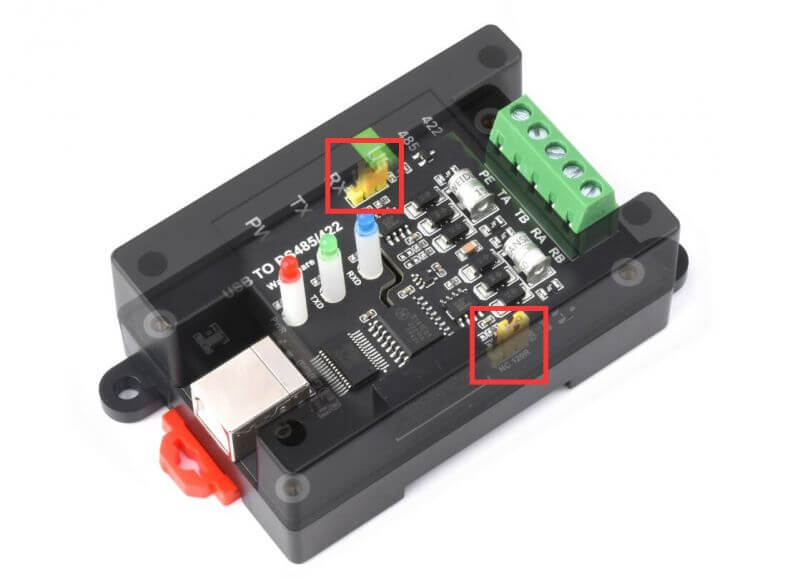
Description: The RS422 and RS485 interfaces of this product also have a built-in 120R enabling resistor, which is enabled by default, and the user can remove the case to modify the settings as needed.
Modification method: Modify the yellow jumper cap at the red frame.
Dimensions

Software Installation
USB Driver Installation
- The first method: download the driver wizard from the Internet, and automatically detect and install the driver.
- The second method: Manually install the driver (the following uses WIN7 installation as an example).
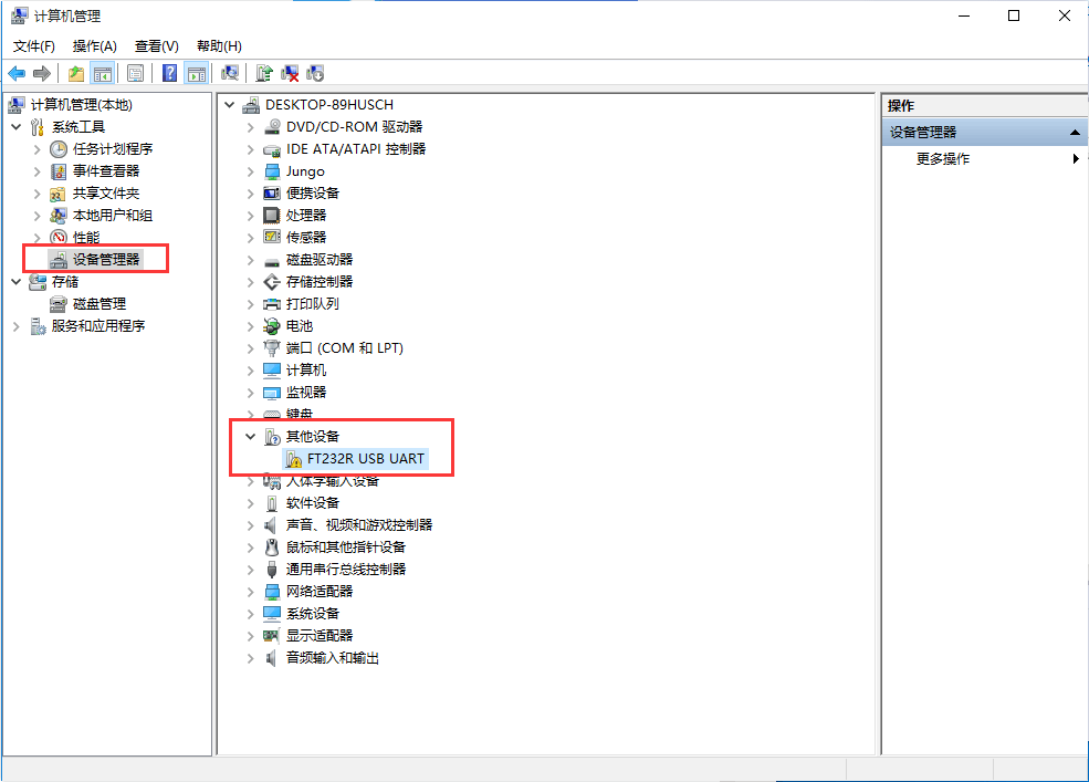
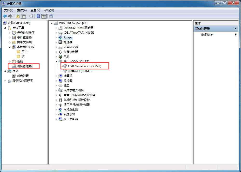
- Connect the device to the computer via a USB cable, and check the device manager, the serial port number has a yellow exclamation mark, indicating that the driver is not installed.
- You can download the software installation package on the official website WIKI, (There must be a path here) Double-click

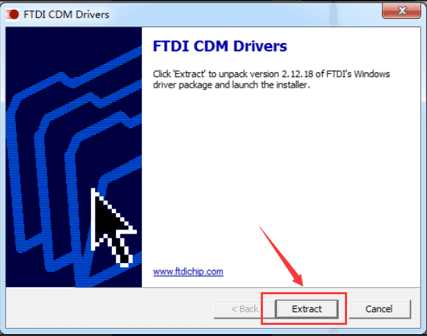
- Click Extract:
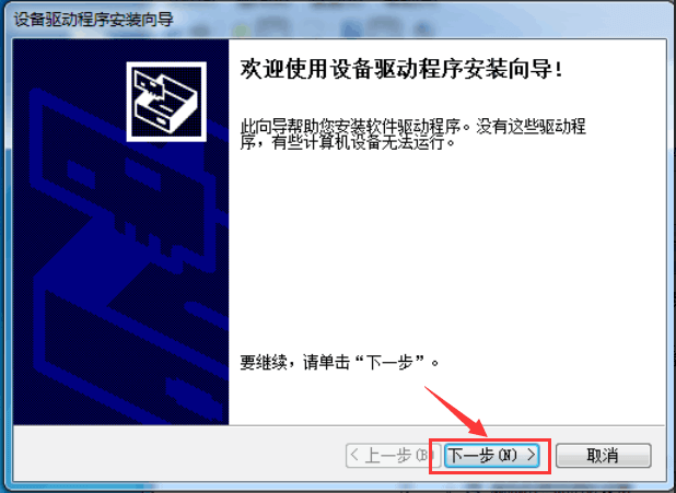
- Click Next:
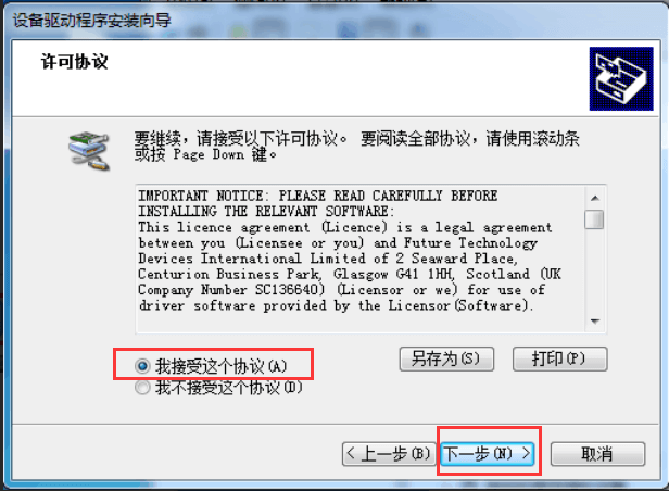
- Check I accept this agreement (A), and then click Next:
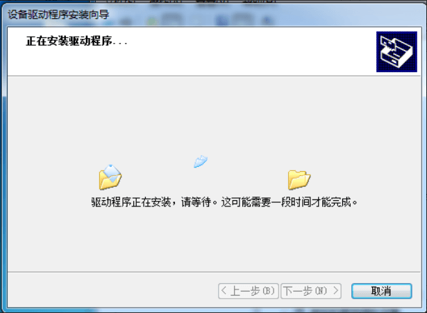
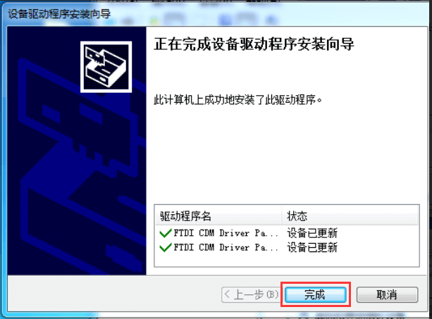
- Click Finish, and check the computer device manager at this time, you can see that the port number is already available for normal use.
Hardware Test
Test environment: PC (Windows system)
Required accessories:
- USB TO RS485/422 x 2pcs
- Adapter cable
RS485 test
- Connect the RS485 interface of the USB TO RS485/422 module, that is, connect TA-->TA to TB-->TB. The hardware connection diagram is as follows:
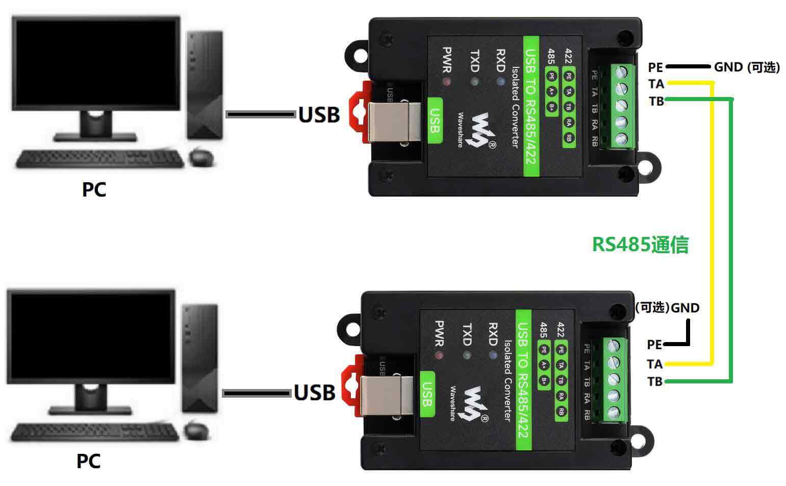
Note: The RS485 interface of this product also has a built-in 120R enabling resistor, which is turned on by default. Users can remove the case to modify the settings according to their needs. If signal isolation is required, PE can also be connected to the ground.
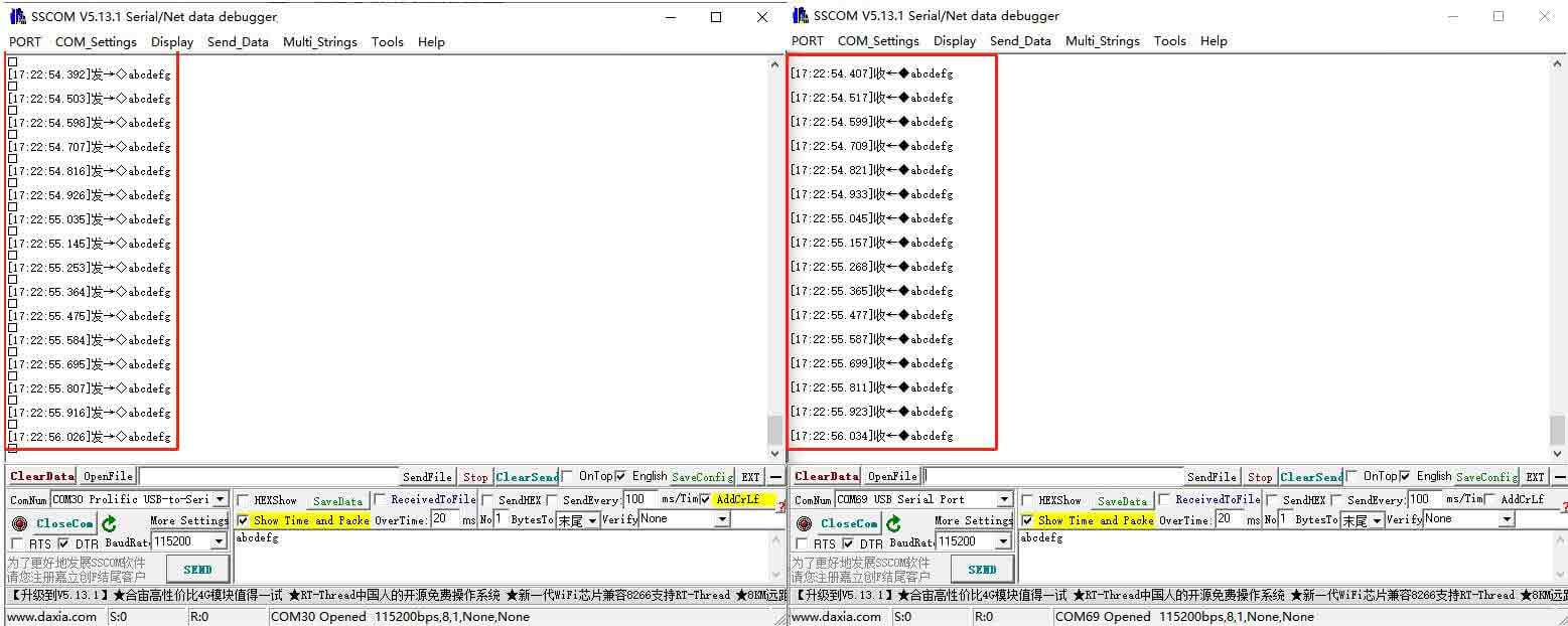
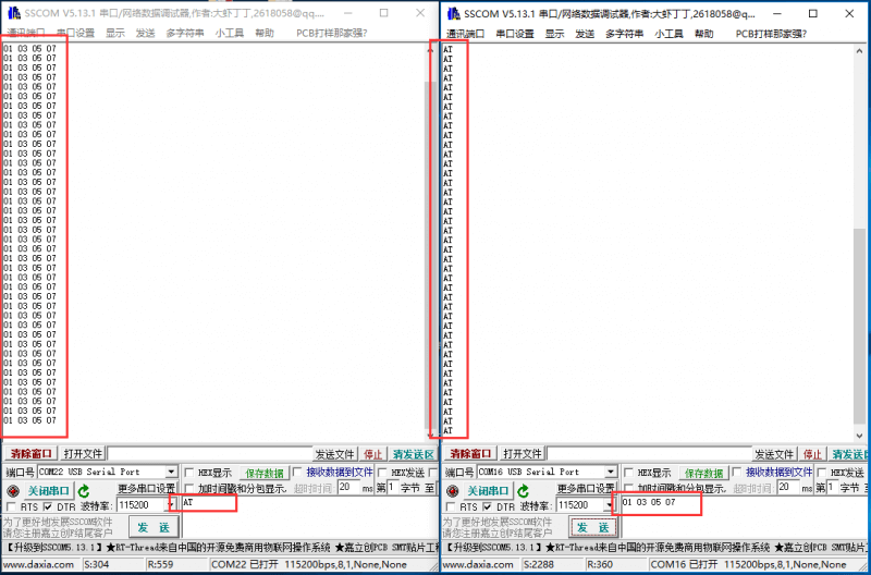
- Open two SSCOM serial port debugging assistants on the computer, open the corresponding port number, set the same baud rate, and click Send at regular intervals to receive and send normally. The test results are shown in the figure below:
RS422 Test
- Connect two sets of USB TO RS485/422 together for communication. When the RS422 interface is connected, cross-connection is required, as shown in the figure below:
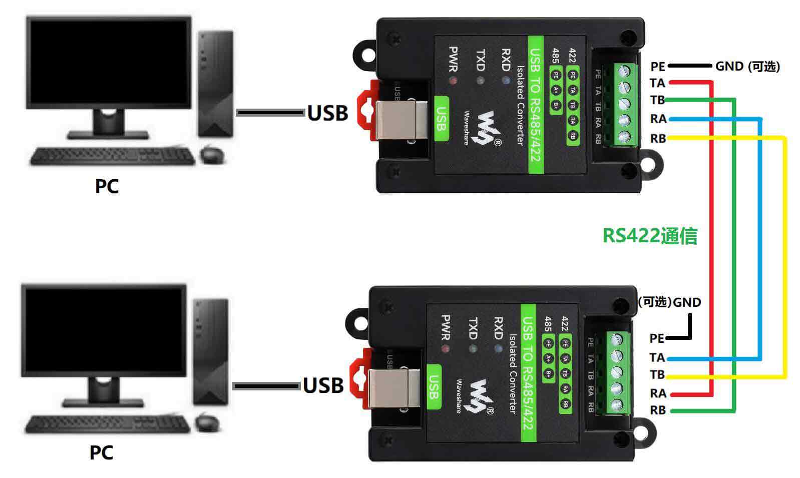
Note: The RS485 interface of this product also has a built-in 120R enabling resistor, which is turned on by default. Users can remove the case to modify the settings according to their needs. If signal isolation is required, PE can also be connected to the ground.
- On the PC, open two SSCOM, open the corresponding port number, set the same baud rate, and click Send at regular intervals to send and receive normally. The screenshot of the software is as shown below: