- sales/support
Google Chat:---
- sales
+86-0755-88291180
- sales01
sales@spotpear.com
- sales02
dragon_manager@163.com
- support
tech-support@spotpear.com
- CEO-Complaints
zhoujie@spotpear.com
- Only Tech-Support
WhatsApp:13246739196
- Purchase/Shipping/Refund
WhatsApp:13424403025
- HOME
- >
- ARTICLES
- >
- For Arduino
- >
- Mother Board
Arduino uno r3 pin diagram function
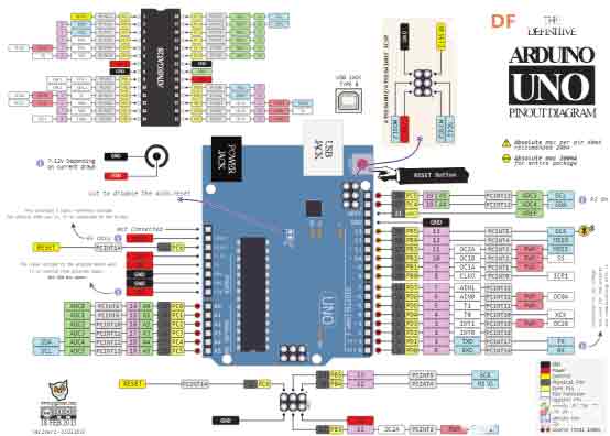
The pinout diagram of the Arduino Uno R3 development board contains 14 digital pins, 6 analog inputs, power jack, USB connection and ICSP header. The multiplexing function of the pins provides more different options, such as driving motors, LEDs, reading sensors, etc. The figure below shows the function of Arduino Uno pins.
Power Pin Description
VIN — When the external DC power supply is connected to the power socket, it can supply power to the outside through VIN; it can also directly supply power to UNO through this pin; when VIN has power, it will ignore the power connected from USB or other pins
5V — Power the 5V chip on the UNO via a voltage regulator or 5V from USB
3.3V — 3.3V voltage generated by the voltage regulator, the maximum drive current is 50mA
GND — ground pin
input Output
The Arduino Uno has 14 digital input and output pins that can be controlled using pinMode(), digitalWrite() and digitalRead().
Some of them have special functions, these pins are as follows:
Serial
0 (RX), 1 (TX), used to receive and send serial port data. These two pins are connected to the ATmega16u2 for serial communication with the computer.
External interrupt 2, 3, can input external interrupt signal. There are four trigger modes for interrupts: low level trigger, level change trigger, rising edge trigger, and falling edge trigger.
PWM output: 3, 5, 6, 9, 10, 11, can be used to output 8-bit PWM wave. Corresponding function analogWrite() .
SPI: 10 (SS), 11 (MOSI), 12 (MISO), 13 (SCK), can be used for SPI communication. It can be manipulated using the official SPI library.
L-LED: 13. An LED is connected to pin 13. When the pin outputs a high level, the LED is turned on, and when the pin outputs a low level, the LED is turned off.
TWI: A4 (SDA), A5 (SCL) and TWI interface, can be used for TWI communication, compatible with I²C communication. It can be manipulated using the officially provided Wire library.
Arduino Uno 6 analog input pins, analog values can be read using analogRead(). Each analog input has 10-bit resolution (ie 1024 different values). By default, the analog input voltage range is 0 to 5V, and other reference voltages can be set using the AREF pin and the analogReference() function.
The relevant pins are as follows:
AREF: Analog input reference voltage input pin.
Reset: Reset the port. Connecting to a low level will reset the Arduino, and when the reset button is pressed, the port will be connected to a low level to reset the Arduino.
Indicator lights (LED) Arduino UNO has 4 LED indicators, the functions are as follows:
ON: Power indicator light. The ON light will light up when the Arduino is powered.
TX: Serial port transmit indicator. The TX light will be on when the USB is connected to the computer and the Arduino is transmitting data to the computer.
RX: serial port receiving indicator light. When the USB is connected to the computer and the Arduino receives data from the computer, the RX light will light up
L: Programmable control indicator light. The LED is connected to pin 13 of the Arduino through a special circuit. When the pin 13 is high or high-impedance, the LED will light up; when it is low, it will not light up. The LED can be controlled to turn on or off by program or external input signal.
Communication
Arduino UNO has a variety of communication interfaces, which can communicate with computers, other Arduinos or other controllers.
ATmega328 provides UART TTL (5V) serial communication, which is located on two pins 0 (RX) and 1 (TX). ATmega16U2 on Uno will simulate a USB serial port on the computer, so that ATmega328 can communicate with the computer. The Arduino IDE provides a serial monitor, which can be used to send and receive simple text data. The RX\TX LEDs on the Uno can indicate the current communication status of the Uno.
The SoftwareSerial library can simulate any digital pin of the Uno as a serial port for serial communication.
The ATmega328 also supports I2C (TWI) and SPI communication. The Wire library that comes with Arduino IDE can be used to drive the I2C bus, and the built-in SPI library can be used for SPI communication.