


- sales/support
Google Chat:---
- sales
+86-0755-88291180
- sales01
sales@spotpear.com
- sales02
dragon_manager@163.com
- support
tech-support@spotpear.com
- CEO-Complaints
zhoujie@spotpear.com
- Only Tech-Support
WhatsApp:13246739196
- Purchase/Shipping/Refund
WhatsApp:13424403025
- HOME
- >
- ARTICLES
- >
- Common Moudle
- >
- ESP
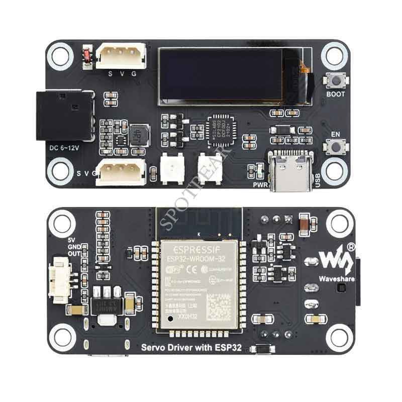
Servo Driver with ESP32 User Guide
Overview
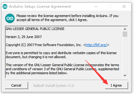
This product is a bus servo control board based on ESP32 and we provide examples that can control bus servos through the WEB application. This product supports the programming of servos to change the ID and working mode of the servos (servo mode/motor mode) in theory, it can control 253 bus servos and read the current angle, load, voltage, mode, and other information of each servo, and can use the serial port to communicate with the upper computer, which is used to build the lower computer of the robot project, and the on-board OLED. The screen can be used to display key information and is suitable for robot projects that require feedback on the angle and load of the servos such as robotic arms, hexapod robots, humanoid robots, wheeled robots, etc.
Product Specifications
- Supply voltage: DC 6-12V(the input voltage and the servo voltage must be matched)
- Controloller: ESP32
- Control interface: UART
- Download interface: Type-C
- Power supply connector: 5.5*2.1mm DC
- Dimensions: 65mm x 30mm
- Fixing hole diameter: 3.0mm
- Mounting hole size: 2.75mm
- Mounting hole spacing: 23 × 58mm
Product Features
- Allows controlling up to 253 SC, ST series serial bus servos at the same time (adequate power supply required).
- Wide range voltage input 6-12V (the input voltage and the servo voltage must be matched).
- Built-in WiFi and Bluetooth, as well as ESP-NOW support, for remote control and servo debugging.
- Automatic download circuit for easy uploading programs.
- Open source web application and various robot structures.
- Compact size and space-saving, suitable for integration into sorts of space-limited projects.
Open Source Project
You can download the relevant open-source robot models in the product documentation for building your own projects.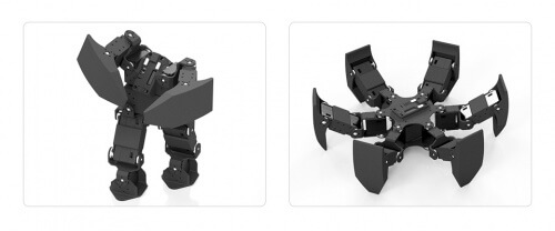
Install Arduino IDE
- You can directly click this link to download the Arduino IDE from Arduino.cc.
- Run the installation package.
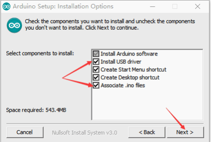
- Click I agree
- Check Install USB driverand Associate.ino files, then click Next.
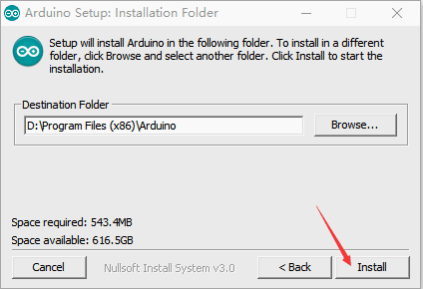
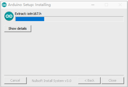
- Select the installation path of Arduino IDE, then click Install.
- Wait for the installation to complete.
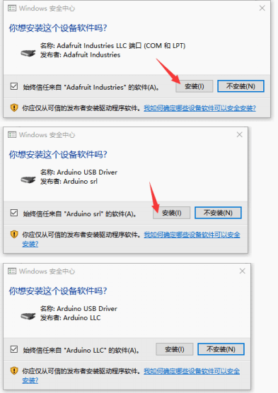
- Install the required drivers.
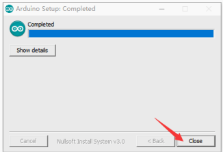
- Arduino IDE installation is complete.
Install the Arduino core for the ESP32
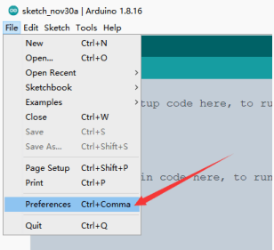
- Run the Arduino IDE and click File .
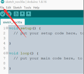
- Click Preferences
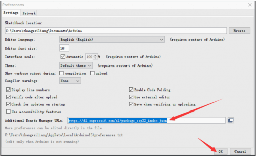
- Fill in https://dl.espressif.com/dl/package_esp32_index.json in Additional Boards Manager URLs. Then click OK.
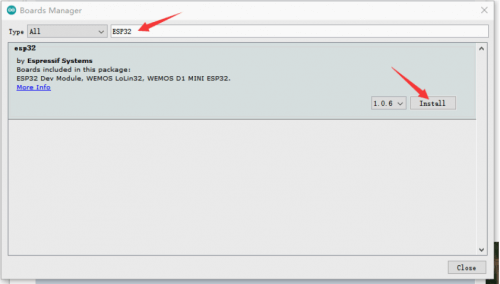
- Restart the IDE, click Tools> Board > Boards Manager, open Boards Manager.
- Fill in ESP32 and click Install.
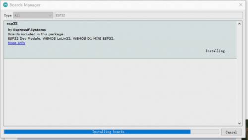
- Wait for the installation to complete.
Download the product program and install the dependency library
Libraries installed through the library manager are:
Adafruit SSD1306
Adafruit_NeoPixel
Libraries installed by copying folders are:
SCServo
- Click Tools > Manage Libraries to open the library manager.
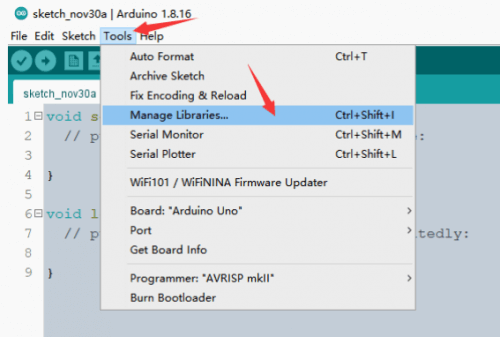
- Enter the names of the libraries that need to be installed through the library manager in the search box in turn, and install them.
Adafruit SSD1306
Adafruit_NeoPixel
Place the mouse on the point Update with Update, and select the latest version without Update and click Install.
- Click this Github link to download the product program locally, or you can download the product program on the Micro Snow official website.
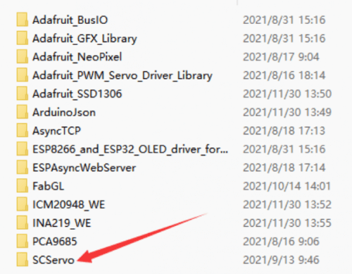
- Copy SCServo to \Documents\Arduino\libraries..
Upload the program to the robot
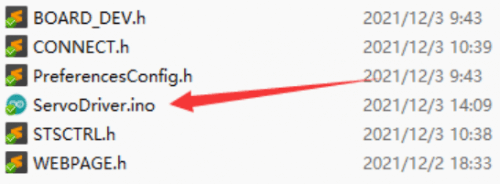
- Double click and run ServoDriver.ino
- Click Tools > Port to remember the existing COM Port, no need to click it.
The COM displayed here is different for different computers, remember that there is a COM now.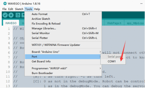
- Connect the driver board and computer.
- Click Tools > Port and click on this new COM.
The newly-appearing COM is different for different computers, click the newly-appearing COM.
If no new COM appears, refer to the USB driver section of the Q&A.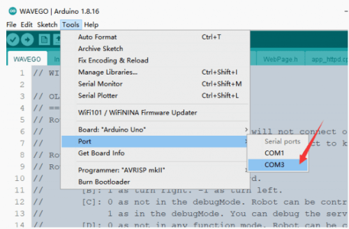
- Click Tools > Boards: > ESP32 Arduino > ESP32 Dev Module, select ESP32 Dev Module.
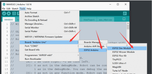
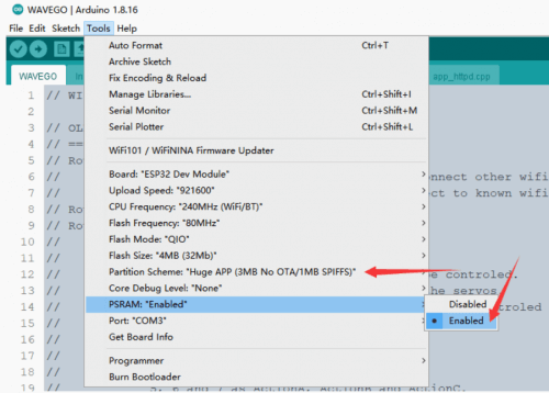
- Other setting are as follows
Upload Speed: "921600"
CPU Frequency: "240MHz(WiFi/BT)"
Flash Frequency: "80MHz"
Flash Mode: "QIO"
Flash Size: "4MB(32Mb)"
Partition Scheme: "Huge APP(3MB No OTA/1MB SPIFFS)"
PSRAM: "Enabled"
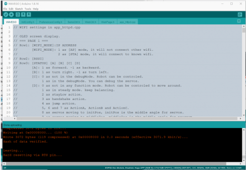
- Click Upload in the upper left corner to upload the program.
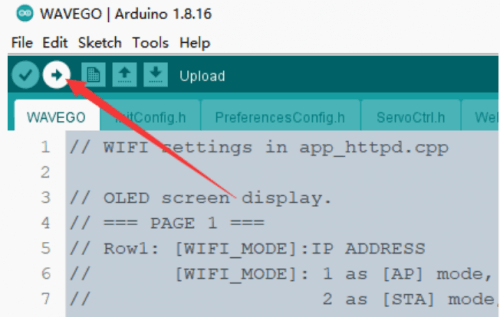
- Wait for the program upload to complete.
- After displaying Leaving... Hard resetting via RTS pin..., it means that the upload has been successful.
Use driver board
- Connect the SC15 Servo servo to the driver board. There are two 3pin servo ports on the driver board. These two ports are connected, so you can connect any one.
- Use 6-8.4V DC power supply, the driver board will automatically turn on after plugging in the power supply.
When powered on, the RGB blue light indicates that the driver board starts to initialize WIFI and establish a WebServer. After completion, the driver board will automatically scan the connected servos. The RGB light is light green during scanning, and the RGB will turn off after scanning.
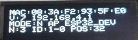
After power on, the first line of OLED is the MAC address of the device, which is unique and used for ESP-NOW communication.
The second row V: is the measured voltage. After the voltage is the device IP address.
The third line MODE: is the role of the device, N is Normal, ESP-NOW related functions are disabled; L is Leader, ESP-NOW will send the current Active Servo ID and position information to Follower, control the rudder with the same ID connected to Follower machine; F is Follower, the device will receive commands from Leader through ESP-NOW.
The role of the device is followed by AP or STA. In AP mode, the device will establish a WIFI hotspot; in STA mode, the device will A known WIFI will be connected.
In AP mode, AP is followed by the SSID of the device; in STA mode, STA is followed by a signal Strength RSSI.
The first line N: is Number, showing the number of servos connected in the last scan; ID: is the currently selected servo (Active Servo), after the servo, -0 indicates that the servo is in servo mode; -3 indicates that the servo is in motor mode. POS: is the current position of the servo.
- Download and install the Chrome browser on your phone, or other browsers with the same kernel.
- In the default program, a WIFI hotspot will be created automatically after the driver board is powered on, and the mobile phone will be used to search for WIFI hotspots.
- In the default program, the WIFI name is ESP32_DEV, and the WIFI password is 12345678.
- After the connection is successful, open the browser and enter 192.168.4.1 in the address bar to open the ESP32 WEB interface.
Under normal circumstances, if the servo is connected first and then powered on, the driver board will scan the connected servo when it is powered on. If you turn on the servo first and then connect the servo, you need to manually click Start Searching on the WEB interface of the mobile phone, and then wait for a while for the servo to scan, including re-scanning the servo after resetting the servo ID.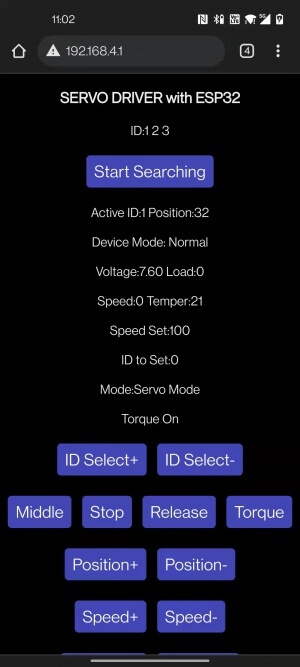
- If you only connect one servo, the ID Select+ and ID Select- buttons are useless; if you connect multiple servos with different IDs, you can use these two Press the key to select the servo, the currently selected servo ID is displayed behind ID: ; if you connect multiple servos with the same ID, it is very likely that the ping will fail, resulting in the driver board without the servo ID. Select, at this time, you need to disconnect the redundant connections, connect only one servo, and connect it in series with the servos of other IDs after changing the ID.
- Middle button, after pressing the servo, the servo will rotate to the middle position of the servo swing range.
- Stop button, the servo will stop turning after pressing it.
- Release button, press the servo to turn off the torque lock, and people can turn the servo by hand (due to the existence of multi-stage reduction gears, it may be very difficult to rotate the steering wheel between them, there must be a force arm to rotate).
- Torque button, press it to open the torque lock, when receiving external force, the servo will try its best to keep it in one position.
- Position+, the servo position value increases after pressing, the servo starts to rotate clockwise, and the rotation stops when released.
- Position-, the servo position value decreases after pressing, the servo starts to rotate counterclockwise, and the rotation stops when released.
- Speed+ Speed-, press to increase/decrease the speed of the servo, the changed speed is displayed after Speed Set:, the speed of the servo will use this speed .
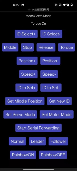
- ID to Set+ ID to Set- Set New ID, used to select the servo ID to be changed, displayed after ID to Set:. For example, when you need to change the servo with ID 3 to servo with ID 9, you need to click
ID Select to change the display area ID: to 3 (the premise is that At this time, there is a servo with ID 3 in the scanned servo), then use the ID to Set button to change the number after ```ID to Set: to 9, and then click Set New ID, click OK or OK in the pop-up dialog box, so that the ID3 servo is set to ID9, then you need to click ```Start Searching``` again to search for the servo .
- Set Middle Position, only for ST series, SC series servos do not have this function, this button is used to set the currently selected servo position as the middle position of the servo.
- Set Servo Mode, set the current servo to servo mode, which is also the initial default mode of the servo, which can be rotated to an absolute position.
- Set Motor Mode, set the current servo to motor mode, in this mode the servo can rotate continuously, can control the relative position of each rotation, and can be used as a geared motor (SC series servo) Or stepper motor (ST series servo).
- Start Serial Forwarding, after turning on the servo, the servo will start the serial port forwarding, and forward the data of the Type-C UART0 and the UART1 used to control the servo, so that the FD tool on the computer can be used to debug the servo , the default baud rate of UART0 is ```115200```.
- Normal, set the current device to `Normal, the related functions of ESP-NOW will not be enabled in this mode.
- Leader, set the current device as Leader, in this mode, the device will send the current Active Servos ID and Position to Follower .
- Follower, set the current device to Leader, in this mode, the device will receive commands from Leader through ESP-NOW.
- RainbowON RainbowOFF, used to turn on and off the RGB rainbow light, you can expand more WS2812 RGB LEDs on the RGB light interface.
Advanced Features
Change max servo ID
The method of scanning the currently connected servos each time is to ping each ID. If Ping passes a certain ID, it means that the servo with this ID is connected to the driver board, so if there are too many IDs to be PINed, it will take a long time. The maximum ID of the scanning servo is defined in ServoDriver.ino, MAX_ID, if you control many servos or the servo ID value is relatively large, you can change this value to Adjust the number of IDs to ping per scan. The maximum is 253, the default is 20.
// set the max ID.
int MAX_ID = 20;
Set MAC address
ESP-NOW is used for communication between the driver boards. The default program supports one-to-one control. You can follow the tutorials later in this section for one-to-many or many-to-one communication.
The premise of ESP-NOW communication is to know the MAC address of the receiver. After the driver board is powered on, it will automatically obtain the MAC address of the device and display it on the first line of the OLED screen.
The working mode of the driver board can be set to Normal Leader Follower, when you use one driver board to control another, the driver board on the control side is Leader, and the other driver board to be controlled is Leader. Follower, the specific steps are as follows:
- Connect Follower to the computer, note down the Follower's MAC address.
- Open ServoDriver.ino, change DEFAULT_ROLE to 2, and upload it to the Follower driver board.
// set the default role here.
// 0 as normal mode.
// 1 as leader, ctrl other device via ESP-NOW.
// 2 as follower, can be controled via ESP-NOW.
#define DEFAULT_ROLE 2
It is not necessary to change the DEFAULT_ROLE step. After changing this, the driver board will automatically be in the corresponding working mode after booting. If you do not change this, you need to manually set it on the WEB page. When the driver boards with the same SSID are running in AP mode at the same time, you may not be able to distinguish which name corresponds to which driver board. For WIFI settings, please refer to the ```WIFI: AP and STA Mode`` chapter.
- Connect the Leader driver board to the computer, open ServoDriver.ino, change broadcastAddress[] to the MAC address of Follower, remember to Add 0x before each value.
// the MAC address of the device you want to ctrl.
uint8_t broadcastAddress[] = {0x08, 0x3A, 0xF2, 0x93, 0x5F, 0xA8};
The above is an example, in practice the MAC address of each device is different.
- Change DEFAULT_ROLE to 1 and upload it to the Follower driver board.
// set the default role here.
// 0 as normal mode.
// 1 as leader, ctrl other device via ESP-NOW.
// 2 as follower, can be controled via ESP-NOW.
#define DEFAULT_ROLE 1
- After the two devices are connected to the servos with the same ID, the ID and Position of the Leader's Active Servo will be sent to the Follower , which controls the rotation of the servo connected to it.
In the example, it is only applicable to the servo working in servo mode, if it is working in the motor mode, it will not work. SC series servos are running continuously. The angle cannot be controlled in motion mode.
When connecting the mobile phone to the driver board, pay attention to whether the SSIDs of the two driver boards have the same name. Connected to wrong driver board.
You can refer to the WIFI: AP and STA Mode section to change the SSID.
ESP-NOW related links link title