


- sales/support
Google Chat:---
- sales
+86-0755-88291180
- sales01
sales@spotpear.com
- sales02
dragon_manager@163.com
- support
tech-support@spotpear.com
- CEO-Complaints
zhoujie@spotpear.com
- Only Tech-Support
WhatsApp:13246739196
- Purchase/Shipping/Refund
WhatsApp:13424403025
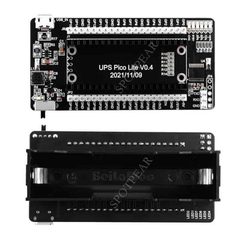
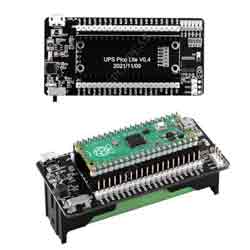
Raspberry Pi PICO UPS Pico Lite V0.4 User Guide
Product description
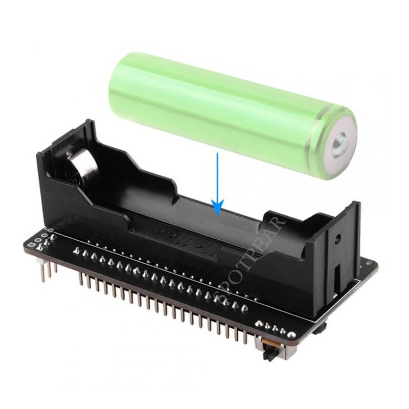
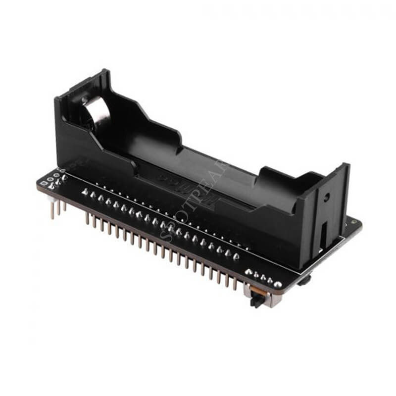
- This is a portable power supply for the Raspberry Pi Pico. Supports the use of a single 18650 lithium battery for power supply, freeing your pico from the shackles of cables and making it more convenient for your DIY Pico projects. The remaining battery power can be read from 4 LED indicators. You can also read battery voltage and current information by connecting a USB to TTL cable to the serial port pins of the UPS. The charging prompt when charging is very intuitive. When the battery is fully charged, it will stop charging and the "standby indicator" on the panel will light up. All GPIOs are lead out and provide clear silkscreen, which is very convenient for Pico experiments.
- It is a plug and play module.
- This device is a power supply device, please pay attention to the positive and negative poles of the battery. Reversing the battery can damage your UPS device or Pico development board. Please check the circuit carefully before turning on the power switch to avoid short circuit damage to the device.
Features
- Plug and Play
- Only supports Raspberry Pi Pico
- Monitor battery voltage (error ±2%), monitor battery current (error ±10%).
- Monitor charging current.
- If not in charging mode, the power LED indicator will not light, wake up every 2 minutes for 5 seconds to reduce light pollution.
- In charging mode, you can judge whether it is fully charged, and stop flashing when fully charged.
- In charging mode, the LED will flash when not fully charged.
- Evenly distribute the power ratio of each LED to prevent the load from popping up.
- Static power consumption is less than 10mA.
- Serial output data.
- Only supports 18650 lithium battery
Serial output data format
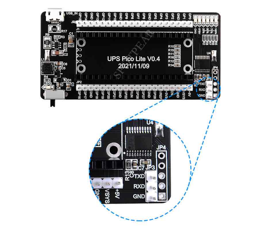
- The parameters are read from the onboard serial port, you can connect the USB-To-TTL line to the pins (TX and RX), Silkmark is JP3.
- NOTE: It is normal to still be able to read the current draw without connecting the PICO and turning the power switch on. After all, the board also consumes less power, which can be ignored.
- Data format: [Battery voltage mV] | [Charging current mA] | [Discharging current X10] mA
- Battery Voltage | Charge Current In | Battery Current
Notice:
- When the data shows a negative sign it means the battery is charging.
- When the data is displayed as positive, it means the battery is draining.
- Data parameters are separated by pipe symbols (delimiter is "|")
- microPython can use the split method to split data information.
- Insert the battery (18650) into the slot.
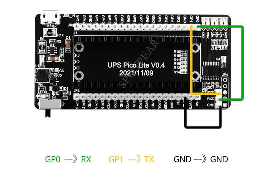
- Connect GP0 to the RX pin and GP1 to the TX pin on the UPS JP3 header.
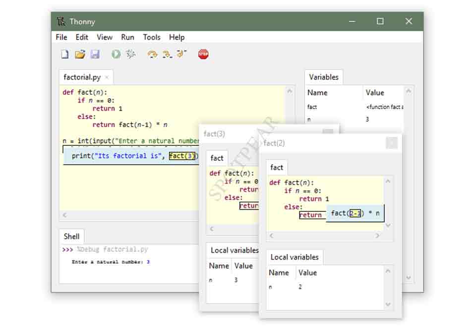
- Open a new file and paste the following code, then press the run button on Thonny IDE.
- Thonny IDE download: [ https://thonny.org/ ]
Pin Definition
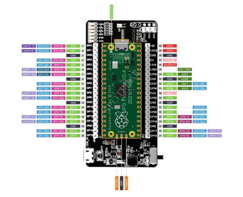
Picture
TAG:
ESP32-C6 LCD Development Board 1.3 inch Display 1.3inch Screen ST7789 240x240 Mini TV SD-Port QST LVGL For Arduino
Milk-V Duo S User Guide Total
Raspberry Pi OpenWrt Tutorial 1
Raspberry Pi Pico
Sensor Development Board
3.4inch Round LCD HDMI Capacitive Touchscreen Display 800x800 For Raspberry Pi/Jetson Nano/mini PC
Supports 6V~24V Solar Panel
RDK X5 PoE Module For Power Over Ethernet/ IEEE 802.3af/at PoE For D-Robotics RDK X5
Arduino Thermal imaging
Raspberry Pi 4B
Raspberry Pi 5
ESP32-P4 Smart 86 TV Box Development Board 4 inch 720x720 Display TouchScreen RS485 Relay Camera RJ45 ETH
Arducam 64MP Camera
Jetson Orin Nano UGV Beast PT ROS2 AI OpenCV Robot Car MediaPipe
Mini Uninterruptible Power Supply module Supports charging And Power output at the same time 5V 2.5A
Milk V
ESP32-S3 A7670E 4G development board supports LTE Cat-1/2G/GNSS positioning/WiFi/Bluetooth
ESP32 C3
ADXL354C Evaluation Board
ESP32-AI Series User Guide
TAG:
Raspberry Pi MLX90640
Raspberry Pi 5
Spotpear Project Customization Raspberry Pi / Arduino / ESP32 / Jeston Nano Related project customization
BPI
Luckfox Aura RV1126B Linux Development Board 3 TOPS Computing Power 2G/4G
Raspberry Pi 5 POE
SpotPear
ESP32 Thermal imaging camera
Raspberry Pi 5 PCIe M.2 Mini NVMe SSD Pi5 Active Cooler
ESP32 S3 Development Board 1.75 inch AMOLED Display TouchScreen SD slot 6-axis sensor Deepseek
1.3inch LCD
Secondary Screen
Arduino 0.85inch LCD
GC2083
TVOC Sensor gas Sensor Expansion board UART High Sensitivity For Arduino /Raspberry Pi /Pico /ESP32
Raspberry Pi DSI LCD
Raspberry Pi Pico
Raspberry Pi 5 Case
ESP32-S3 1.28inch Round Display
Raspberry Pi 5 8 inch DSI LCD Captive TouchScreen MIPI Display 1280x800