- sales/support
Google Chat:---
- sales
+86-0755-88291180
- sales01
sales@spotpear.com
- sales02
dragon_manager@163.com
- support
tech-support@spotpear.com
- CEO-Complaints
zhoujie@spotpear.com
- Only Tech-Support
WhatsApp:13246739196
- Purchase/Shipping/Refund
WhatsApp:13424403025
- HOME
- >
- ARTICLES
- >
- Common Moudle
- >
- UART Module
USB-TO-TTL-FT232 User Guide
Overview
Introduction
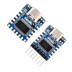
The USB-TO-TTL-FT232 is a UART serial module that converts a USB interface to TTL level. With this converter, a computer or other device with a USB interface can connect to TTL logic level devices, such as microcontrollers, sensors, and more, enabling data communication.
Features
- Onboard original FT232RNL chip, fast communication, stable and reliable, better compatibility.
- Castellated holes design, compact size, easy to integrate into the device by soldering.
- UART communication baudrate: 300bps~3Mbps.
- Onboard self-recovery fuse and ESD diode, provides over-current/over-voltage protection, stable and safe operation.
- Onboard TXD and RXD indicators for monitoring transceiver status.
- Reserved VCC switching pads on the back, using 3.3V TTL by default, allows switching to 5V by re-soldering.
- Adapting all function pins of the chip, more convenient for secondary development and integration.
- Onboard USB Type-C port, smoothly plug & pull, solid and reliable.
Parameters
| Items | Parameters |
| Model | USB to UART TTL |
| Power Supply | 5V |
| Serial Port (TTL Level) | 3.3V/5V |
| Baud Rate | 300bps ~ 3Mbps |
| Operating System | Support Win7/8/8.1/10/11, Mac, Linux, Android, WinCE... |
Onboard Interface
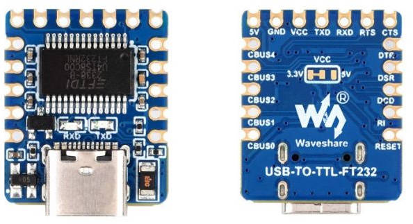
| Pin | Function | Input/Output |
| 5V | Provide 5V to external devices | - |
| GND | Ground | - |
| VCC | Provide 5V or 3.3 to external devices (By selecting the output voltage via the solder pads on the back.) | - |
| TXD | Serial Data Transmitting pin, connect to MCU.RX | Output |
| RXD | Serial Data Receiving pin, connect to MCU.TX | Input |
| RTS | Send requests, connect to MCU.CTS | Output |
| CTS | Clean requests, connect to MCU.RTS | Input |
| DTR# | Data terminal ready, for control external devices, low active | Output |
| DSR# | Data set ready, detect whether the external device is ready, low active | Input |
| DCD# | Data carrier detection, low active | Input |
| RI# | Ring indicator, detect whether the external device rings, low active | Input |
| RESET# | FT232 reset pin, low active (pull low RESET pin, FT232 reset) | Input |
| CBUS0-CBUS4 | Configurable function pin | Output/Input |
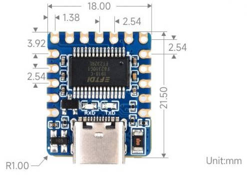
Dimensions
How to Use
Driver Installation
- Download the driver file VCP Driver
- Double click on CDM212364_Setup.exe and install it.
- Click on Extract, and then "NEXT".
- Click on I accept this agreement, and then click on "NEXT", and click on "Finish".
- After connecting the PC, you can see the usable COM port number in the device manager.
Device
SSCOM Usage
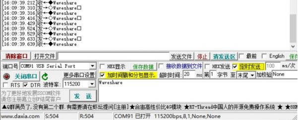
- Connect the TXD and RXD pins of the device.
- Open SSCOM, input "waveshare", select "Show Time and Packet", set the baudrate and then click on "Open COM".
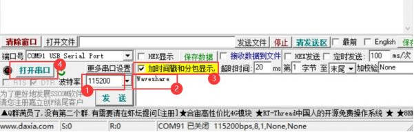
- Select Send Every 100ms, and you can see the device sends and receives data:
Linux
Take RPI as an example, use the default driver, connect the device, and query the serial device name through the following command:
lsusb
ls /dev/ttyUSB*
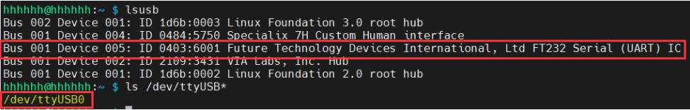
For example, use minicom to open UART0, input the following command line:
sudo minicom -D /dev/ttyUSB0
Android
- Download SerialTool_Android.
- FT232 driver is included in the above APP, there are no external drivers required.
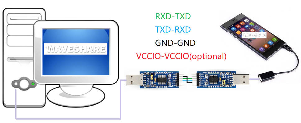
- Connect USB-TO-TTL-FT232 to your Android phone with an OTG cable, and then connect them to another USB-TO-TTL-FT232 and your PC.
- It will prompt: Whether to allow the APP to visit the USB device, please click "OK".
- Input the string to be sent in the Android serial tool, the computer can receive the corresponding on the sscom, and vice versa.
MacOS
- First, click to download and install the driver.
- Driver installation tutorial: click here to view.
After installation, open the serial port assistant and run it (you can download the serial port assistant online for your MAC).
Resource
Driver
- Click the links below to download or download from FTDI official website:
- Windows — VCP Driver
- MacOS — VCP Driver
- Linux supports FTD devices, so no driver is required.
Software
Datasheet
FAQ
Question:How to use 5 configurable pins of the USB-TO-TTL-FT232?
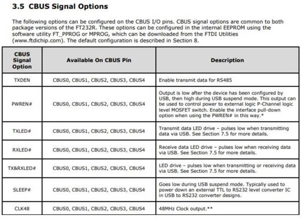
- Configure the internal EEPROM of USB-TO-TTL-FT232 through the official FTDI software FT_Prog , and the configurable functions as shown below:
- How to Configure the original TXD indicator as power indicator:
1. Download and install the configuration software FT_Prog.
2. Connect the USB port of the product and double click the FT_Prog software to open it.
3. Click the magnifying glass icon in the red box to view the configuration of the device that has been connected to the USB port, and click in the order of the figure to view the default configuration of the five function pins: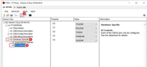
4. Select C0 as PWREN#, and then click the saving icon to save it in the path you want to place, and then click the command box on the above:
5. Input SCAN and then press Enter key, then you can view the connected devices (if not, please repeat this step one more time):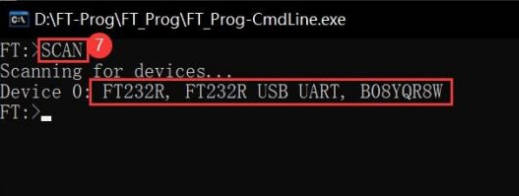
6. Input "prog 0 F:\Burnprocess\1.xml" after finding the device, and press the Enter key. It will prompt "successfully" once the programming is OK (Please modify F:\Burnprocess\1.xml as the path where you save the programming file and the name of the programming file should be modified as the one you saved.)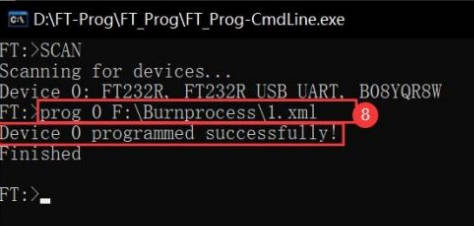
7. Pull and plug the USB interface of the device again, and then you can see that the original TXD indicator is changed to the normally-on PWR indicator.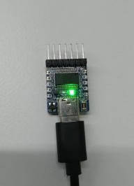
【If you want to restore it, you can configure C0 as TXLED according to the above steps.】
Question:What is the max. current ratings when providing 5V and 3.3V DC output pins?
This USB 5V current follows the current. For example, if it is connected to the USB2.0 of the computer, it is 500mA. If you are using 3.3V, the maximum current output is 50mA.