


- sales/support
Google Chat:---
- sales
+86-0755-88291180
- sales01
sales@spotpear.com
- sales02
dragon_manager@163.com
- support
tech-support@spotpear.com
- CEO-Complaints
zhoujie@spotpear.com
- Only Tech-Support
WhatsApp:13246739196
- Purchase/Shipping/Refund
WhatsApp:13424403025
RP2350-Touch-AMOLED-1.43 User Guide
Overview
Introduction
RP2350-Touch-AMOLED-1.43 is a low-cost, high-performance MCU board designed by Waveshare. It is equipped with a 1.69inch capacitive touch LCD screen, a lithium battery charging chip, a six-axis sensor (three-axis accelerometer and three-axis gyroscope), RTC, buzzer and other peripherals, which are convenient for development and embedding into the product.
Features
- Adopts unique dual-core and dual-architecture design, equipped with dual-core ARM Cortex-M33 processor and dual-core Hazard3 RISC-V processor, flexible clock running up to 150 MHz
- Built-in 520KB of SRAM and 16MB of on-chip Flash
- Onboard 1.43inch AMOLED display, 466 × 466 resolution, supporting 16.7M color
- AMOLED screen display uses an SPI interface, capacitive touch screen uses an I2C interface, supporting interrupt output
- Onboard QMI8658 6-axis IMU (3-axis accelerometer and 3-axis gyroscope) for detecting motion gesture, step counting, etc.
- Built-in PCF85063 RTC chip, with a reserved SH1.0 battery slot (supporting charging) for RTC functionality implementation
- Onboard RST and BOOT side buttons
- Onboard 3.7V MX1.25 lithium battery recharge/discharge header
- Built-in TF card slot, supports external TF card storage for images or files
- Onboard USB Type-C port for power supply, downloading and debugging, making development more convenient
- Lead out the UART and I2C SH1.0 4PIN interface, and reserve a 2×14PIN 1.27mm pitch interface
- Optional CNC exquisite shell, clearly marked, beautiful and portable
- USB1.1 host and device support
- Low-power sleep and dormant modes
- Temperature sensor
- Accurate clock and timer on-chip
- On-chip accelerated floating-point library
Specifications
| AMOLED parameters | |||
| Display Panel | AMOLED | Display Size | 1.43inch |
| Display Resolution | 466(H)RGB x 466(V) | Display Color | 16.7M |
| Display Brightness | 350cd/m2 | Contrast | 60000:1 |
| Communication interface | SPI | Driver IC | CO5300 |
| Touch | Supported | Touch IC | FT6146 |
| IMU parameters | |||
| Sensor Name | QMI8658 | ||
| Accelerometer Characteristics | Resolution: 16 bits Measuring Range (optional): ±2, ±4, ±8, ±16g | ||
| Gyroscope Characteristics | Resolution: 16 bits Measuring Range (optional): ±16, ±32, ±64, ±128, ±256, ±512, ±1024, ±2048°/sec | ||
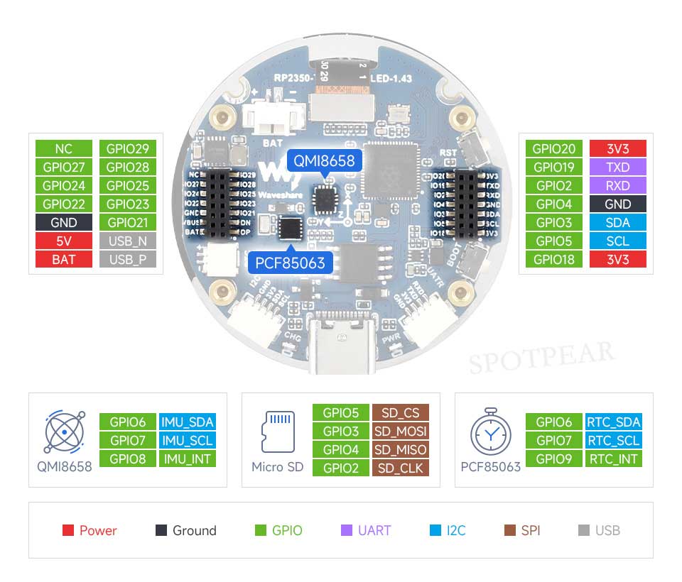
Pinout Definition
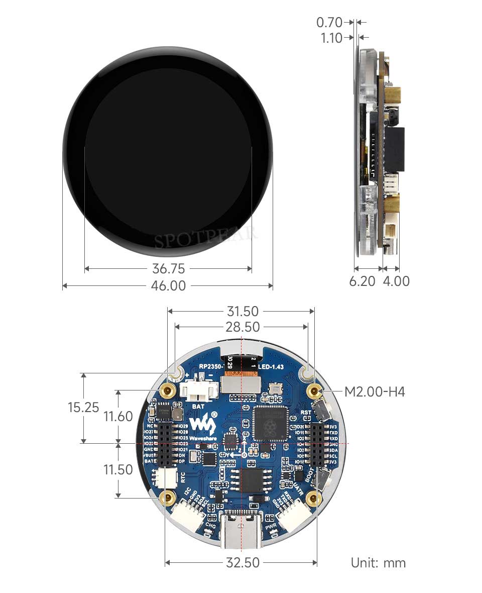
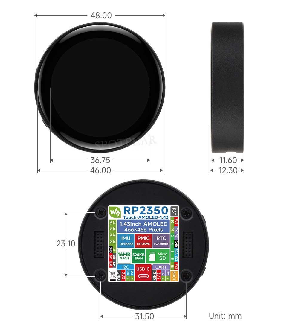
Dimensions
Pico Getting Started
Firmware Download
- MicroPython Firmware Download

- C_Blink Firmware Download

Basic Introduction
MicroPython Series
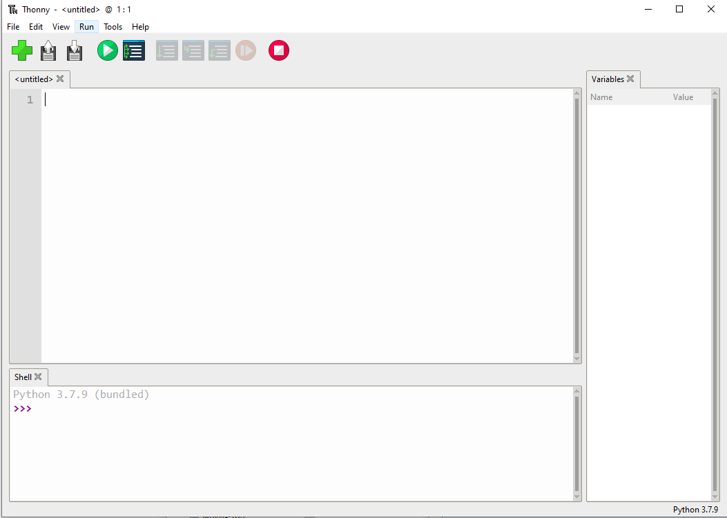
Install Thonny IDE
In order to facilitate the development of Pico/Pico2 boards using MicroPython on a computer, it is recommended to download the Thonny IDE
- Download Thonny IDE and follow the steps to install, the installation packages are all Windows versions, please refer to Thonny's official website for other versions
- After installation, the language and motherboard environment need to be configured for the first use. Since we are using Pico/Pico2, pay attention to selecting the Raspberry Pi option for the motherboard environment
- Configure MicroPython environment and choose Pico/Pico2 port
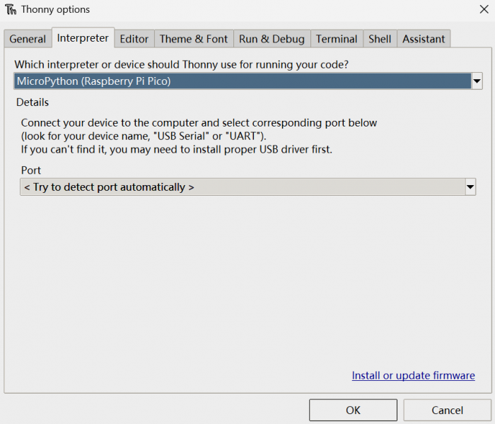
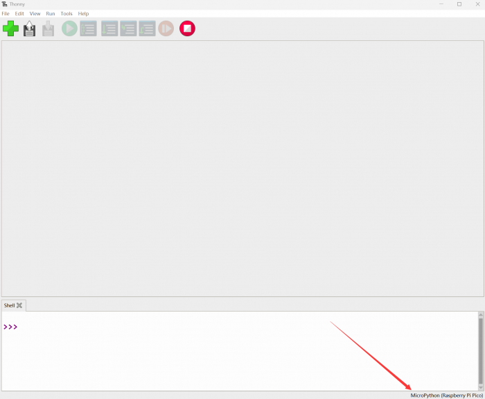
- Connect Pico/Pico2 to your computer first, and in the lower right corner of Thonny left-click on the configuration environment option --> select Configture interpreter
- In the pop-up window, select MicroPython (Raspberry Pi Pico), and choose the corresponding port

Flash Firmware
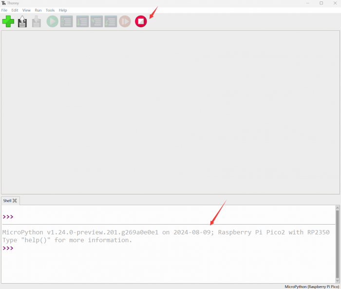
- Click OK to return to the Thonny main interface, download the corresponding firmware library and burn it to the device, and then click the Stop button to display the current environment in the Shell window
- Note: Flashing the Pico2 firmware provided by Micropython may cause the device to be unrecognized, please use the firmware below or in the package
- How to download the firmware library for Pico/Pico2 in windows: After holding down the BOOT button and connecting to the computer, release the BOOT button, a removable disk will appear on the computer, copy the firmware library into it
- How to download the firmware library for RP2040/RP2350 in windows: After connecting to the computer, press the BOOT key and the RESET key at the same time, release the RESET key first and then release the BOOT key, a removable disk will appear on the computer, copy the firmware library into it (you can also use the Pico/Pico2 method)
MicroPython Series Tutorials
【MicroPython】 Machine.Pin Functions
- machine.Pin(id, mode=None, pull=None, value)
- Pin object constructor
- id: GPIO number, the value is 0-29, if GPIO13 is used, fill in 13, here. ;
- mode: mode, optional None, Pin.IN(0), Pin.OUT(1), Pin.OPEN_DRAIN(2);
- pull: use internal pull-up and pull-down resistors, only valid in input mode, optional None, Pin.PULL_UP(1), Pin.PULL_DOWN(2);
- value: port value in output or open-drain mode, 0 is low (off), 1 is high (on);
The first parameter ID represents the GPIO number, and the value should be 0-29. If GPIO13 is used, fill in 13 here.
The second parameter mode represents the GPIO mode and can be set to no initialization, input mode, output mode and open-drain mode
The third parameter pull is to use the internal pull-up and pull-down resistor, which can be set to pull-up, pull-down and floating. Note that this parameter is only valid in input mode.
The fourth parameter is the output value, and the port value is valid in output or open-drain mode.
- Pin.init(mode=None, pull=None)
- Reinitialize the GPIO port;
- mode: mode, optional None, Pin.IN(0), Pin.OUT(1), Pin.OPEN_DRAIN(2);
- pull: use internal pull-up and pull-down resistors, only valid in input mode, optional None, Pin.PULL_UP(1), Pin.PULL_DOWN(2);
Its function is to re-initialize the GPIO, and the parameters are the same as the PIN constructor, so I won't go into details here.
- Pin.value([x])
- Returns the value of the GPIO port without filling in the parameter, and writes the parameter into the GPIO port when filling in the parameter, the parameter can be 0 or 1;
The value function in the PIN class is used to return the value of the GPIO port without filling in the parameter, and write the parameter into the GPIO port when the parameter is filled in, and the parameter can be 0 or 1;
- Pin.toggle()
- Flip port settings in output or open-drain mode
- The toggle function in the PIN class is a flip of the port value in output or open-drain mode
- Pin.low()
- Set the port low in output or open-drain mode;
- Pin.off()
- Set the port low in output or open-drain mode;
- Pin.high()
- Set the port high in output or open-drain mode;
- Pin.on()
- Set the port high in output or open-drain mode;
- The above four functions are used in output or open-drain mode, Low OFF is set to low, high and on are set to high.
- Pin.irq(handler=None,trigger=(Pin.IRQ_FALLING | Pin.IRQ_RISING))
- Used to set external interrupt
- handler: interrupt trigger callback function;
- trigger: interrupt trigger condition, set to:
- Pin.IRQ_FALLING Falling edge interrupt.
- Pin.IRQ_RISING interrupt on rising edge
The PIN class irq function is an external interrupt function, the first parameter is the interrupt trigger callback function; the second parameter trigger is the interrupt trigger condition, which is set to edge trigger or level trigger.
This article is only for RP2040 MicroPython firmware, and the source code shall prevail. This article is written according to the official source code at the time of writing, which is used to provide convenience for beginners and is for reference only. Those who are capable are recommended to refer to MicroPython.
【MicroPython】machine.PWM Function
- machine.PWM(pins):
- PWM object constructor
- pin: GPIO object that needs to be set as PWM output;
Its function will reinitialize the specified GPIO and set it to PWM output mode.
The first parameter pin is the Pin object explained in the previous tutorial, which is used to specify the use of GPIO, and the object will be reinitialized.
- PWM.deinit():
- Cancel PWM initialization.
deinit is a deinitialization function whose function is to clear initialization and stop PWM output.
- PWM.freq([value]):
- Sets the PWM output frequency function.
- value: PWM output frequency, the value should conform to the PWM frequency calculation formula;
The freq function is a PWM frequency setting function that automatically calculates the frequency divider parameter (frequency division factor) and the TOP register parameter (counter maximum count value) according to the parameter value.
- PWM.duty_u16([value]):
- Set the counter comparison value,
- value: Set the duty ratio, the value should be between 0-65536;
The duty_u16 function is used to set the duty cycle. Through the parameter value, the corresponding value will be automatically calculated and given to the CC register. When the counter count value is smaller than the CC register, the PWM pin outputs a high level, otherwise it outputs a low level.
- PWM.duty_ns([value]):
- Set the time of high level;
- value: Set the high level time, the unit is ns;
The role of the duty_ns function is to set the duration of a cycle to output a high level. Its parameter value is the high level time in ns.
This article is only for RP2040 MicroPython firmware, and the source code shall prevail. This article is written according to the official source code at the time of writing, which is used to provide convenience for beginners and is for reference only. Those who are capable are recommended to refer to MicroPython.
【MicroPython】machine.ADC Function
- machine.ADC(id):
- ADC object constructor, and initialize the corresponding channel.
- id: can be a GPIO object or an ADC channel;
The ADC object constructor is used to initialize the corresponding ADC channel. The parameter ID is the ADC channel used. You can use the Pin object or directly specify the ADC channel.
When using the Pin object, the specified GPIO needs to support the ADC function, namely GPIO26-29;
Use the specified ADC channel, channel 0-3 corresponds to GPIO26-29, channel number 4 corresponds to the internal temperature sensor.
- ADC.read_u16():
- Read the ADC value of the corresponding channel
The read_u16 function reads the corresponding channel ADC and returns the read value;
It should be noted here that the return value of this function does not directly return the value read by the ADC, but the processed value, and its value range is 0-65535;
Therefore, the ADC voltage calculation formula should be:
Vin =\frac{3.3*ReadData}{65535}Vin=655353.3∗ReadData
The ADC read voltage is 3.3 times the return value divided by 65535 in V
This article is only for RP2040 MicroPython firmware, and the source code shall prevail. This article is written according to the official source code at the time of writing, which is used to provide convenience for beginners and is for reference only. Those who are capable are recommended to refer to MicroPython.
【MicroPython】machine.UART Function
- machine.UART(id,baudrate=115200,bits=8,parity=None,stop=1,tx=None,rx=None):
- UART object constructor, used to initialize the corresponding channel and pin.
- id: use the UART channel, which can be 0 or 1;
- baudrate: baud rate parameter
- bits: data bit length
- parity: parity bit
- stop: stop bit length
- tx: TXD pin, should be a Pin object
- rx: RXD pin, should be a Pin object
machine.UART is the constructor of the UART object, which is used to initialize the corresponding channel and pin. D The first parameter id is to use the UART channel, which can be 0 or 1.
The second parameter baudrate is the baud rate used.
The third parameter bits is the data bit length (only 8 bits are valid at this stage).
The fourth parameter parity is whether to use the parity bit.
The fifth parameter stop is the length of the stop bit.
The sixth and seventh parameters tx and rx are transceiver pins, which should be Pin objects.
- UART.any():
- The any function is used to detect whether there is data in the current receive buffer. If there is data in the receive buffer, it returns 1, otherwise it returns 0.
- UART.read([nbytes]):
- The read function is used to read strings.
- nbytes: If 'nbytes is specified, read at most this many bytes, otherwise read as much data as possible.
- UART.readline()
- The readline function reads a line, ending with a newline character.
- UART.readinto(buf[, nbytes])
- readinto: store the read string in the specified buffer
- buf: used to specify the cache
- nbytes: If 'nbytes is specified, read at most this many bytes, otherwise read as much data as possible.
- The readinto function stores the read string in the specified cache. buf is used to specify the cache nbytes and the function of the read function nbytes above is the same
- UART.write(buf)
The write function, used to send a string, returns the number of bytes sent by the value. buf: Sending a string The write function is used to send a string and return the number of bytes sent. The parameter buf is the string to be sent.
- UART.sendbreak()
The sendbreak function sends a stop signal on the bus. This will drive the bus low for longer than the normal transmission of the character takes.
【MicroPython】machine.I2C Function
- machine.I2C(i2c_id,scl,sda,freq=400000)
- The I2C object constructor is used to initialize the corresponding channel and pin.
- i2c_id: Use the I2C channel, which can be 0 or 1;
- scl: SCL pin, should be a Pin object (I2C0 defaults to 9, I2C1 defaults to 7)
- sda: SDA pin, should be a Pin object (I2C0 defaults to 8, I2C1 defaults to 6)
- freq: I2C clock frequency, the default is 400Kb/S
- I2C.scan()
- The scan slave function returns a list of all 7-bit addresses of slave devices mounted on the I2C bus.
- I2C.readfrom(addr, nbytes, stop=True)
- The function of readfrom is to read data from the device through the I2C bus and return a byte string.
- addr: slave device address.
- nbytes: read character length.
- stop: Whether to send the end signal after receiving the completion data.
- I2C.readfrom_into(addr, buf, stop=True)
- The readfrom_into function is an upgraded version of the readfro function, which can specify the read data to be stored in a character array.
- addr: slave device address
- buf: character array, used to store data
- stop: whether to send the end signal after receiving the completion data
- I2C.writeto(addr, buf, stop=True)
- The writeto function is used to write data to the slave device.
- addr: slave device address
- buf: send string
- stop: whether to send the end signal after receiving the completion data
Memory Operation
- I2C.readfrom_mem(addr, memaddr, nbytes, *, addrsize=8)
- The readfrom_mem function is used to read data from the register of the device.
- addr: slave device address
- memaddr: register address
- nbytes: read length in bytes
- addrsize: register address length
- I2C.readfrom_mem_into(addr, memaddr, buf, *, addrsize=8)
- The readfrom_mem_into function is used to read data from the register of the device to the specified character array.
- addr: slave device address
- memaddr: register address
- buf: character array, used to store data
- addrsize: register address length
- I2C.writeto_mem(addr, memaddr, buf, *, addrsize=8)
- The writeto_mem function is used to write data to the register of the slave device
- addr: slave device address
- memaddr: register address
- buf: send string
- addrsize: register address length
Software I2C
- I2C.start()
- The start function is used to send a start signal in the I2C bus (SCL remains high, SDA turns low)
- I2C.stop()
- The start function is used to send a termination signal in the I2C bus (SCL remains high, SDA turns low)
I2C.readinto(buf, nack=True,)
- The function of readinto is to read data from the I2C bus to the specified character array, and the read length is the length of the character array.
- buf: character array to store data
- nack: whether to send a nack signal after receiving the last data
- I2C.write(buf)
- The function of the write function is to write the data of the buf character array to the I2C bus.
- buf: array of characters to send
Demo Address
This article is only for RP2040 MicroPython firmware, and the source code shall prevail. This article is written according to the official source code at the time of writing, which is used to provide convenience for beginners and is for reference only. Those who are capable are recommended to refer to MicroPython.
【MicroPython】machine.SPI Function
- machine.SPI(id,baudrate=1000000, polarity=0, phase=0, bits=8, firstbit=SPI.MSB, sck=None, mosi=None, miso=None)
- SPI object constructor, used to initialize the corresponding channel and pin
- id: use SPI channel, can be 0 or 1
- baudrate: SPI communication rate, which is the frequency on the SCK pin
- polarity: Clock polarity, if it is 0, SCK outputs a low level when the bus is idle, otherwise it outputs a high level.
- phase: the clock phase, if it is 0, the data is captured on the first clock edge, otherwise, the data is captured on the second clock edge.
- bits: the number of data bits per transfer
- firstbit: transmit high or low bits first
- sck: SCK pin, should be a Pin object
- mosi: MOSI pin, should be a Pin object
- miso: MISO pin, should be a Pin object
- sck, mosi and miso are all pins used by SPI and should be Pin objects
- SPI.init()
- init function, used to restart SPI
- SPI.deinit()
- deinit function, used to close the SPI
- SPI.read(nbytes,write=0x00)
- read function, used to read data from the device and return
- nbytes: number of bytes read
- write: When reading data, MOSI outputs data.
- SPI.readinto(buf,write=0x00)
- The readinto function is used to read data from the device and store it in the specified character array.
- buf: character array, used to store received data
- write: When reading data, MOSI outputs data.
- SPI.write(buf)
- write function, which writes a character array to the slave device.
- buf: character array, used to store transmission data
- SPI.write_readinto(write_buf, read_buf)
- write_readinto function for sending and receiving data at the same time
- write_buf: character array, used to store transmission data
- read_buf: character array, used to store received data
- PS: The length of the character array for transmitting and receiving data here is required to be consistent.
Demo Address
This article is only for RP2040 MicroPython firmware, and the source code shall prevail. This article is written according to the official source code at the time of writing, which is used to provide convenience for beginners and is for reference only. Those who are capable are recommended to refer to MicroPython.
【MicroPython】PIO Function
MicroPython introduces a new @rp2.Asm_pio decorator and rp2.PIO class.
- The definition of the PIO program and the configuration of the state machine are divided into 2 logical parts:
1. Program definition, including how many pins are used and if they are in/out pins. This is defined in @rp2.asm_pio.
2. Program, which sets the frequency of the state machine and which pin to bind to. These parameters are set when a state machine is set up to run a specific program.
All program configuration (such as autopull) is done in the @asm_pio decorator. Only setting the frequency and base pins needs to be set in the StateMachine constructor.
@asm_pio
@asm_pio(
    out_init=None,
    set_init=None,
    sideset_init=None,
    in_shiftdir=0,
    out_shiftdir=0,
    autopush=False,
    autopull=False,
    push_thresh=32,
    pull_thresh=32,
    fifo_join=0
)
- out_init: initialize the output pin
- set_init: set the pin initialization
- sideset_init: side set the pin initialization
- in_shiftdir: data input direction
- out_shiftdir: data output direction
- autopush: if it is enabled, ISR will be transmitted to RX-FIFO automatically when ISR has reached the threshold.
- autopull: if it is enabled, TX-FIFO will be transmitted to OSR automatically when OSR has reached the threshold.
- push_thresh: push threshold
- pull_thresh: pull threshold
- fifo_join: Fifo combination, specify a FIFO, close the other FIFO and add it to the FIFO to get a FIFO with deeper bits.
rp2.StateMachine Function
- rp2.StateMachine.init(sm_id ,program, freq=-1, *, in_base=None, out_base=None, set_base=None, jmp_pin=None, sideset_base=None, in_shiftdir=None, out_shiftdir=None, push_thresh=None, pull_thresh =None)
- sm_id: Use state machine ID
- program: PIO running program
- freq: the operating frequency of the state machine, the default is the system clock frequency,
- The distribution factor for the clock divider is calculated as "system clock frequency/frequency", so there may be slight rounding errors.
- The smallest possible clock divider is 1/65536 of the system clock: so at the default system clock frequency of 125MHz, the minimum is 1908.
- To run the state machine at a slower frequency, use "machine.freq()" to reduce the system clock speed.
- in_base: the first pin for the in() instruction
- out_base: the first pin for the out() instruction
- set_base: the first pin for the set() instruction
- jmp_pin: the first pin for the jmp(pin, …) instruction
- sideset_base: is the first pin for sideset.
- in_shiftdir: The direction in which the ISR will move, which can be PIO.SHIFT_LEFT or PIO.SHIFT_RIGHT
- out_shiftdir: The direction in which the OSR will move, which can be PIO.SHIFT_LEFT or PIO.SHIFT_RIGHT
- push_thresh: push threshold
- pull_thresh: pull threshold
- StateMachine.active([value])
- Gets or sets whether the state machine is currently running.
- When the value is not empty, set the state machine, otherwise get the running state.
- StateMachine.restart()
- Restart the state machine and jump to the beginning of the program.
- StateMachine.exec(instr)
- Execute a single PIO instruction. Use asm_pio_encode to encode instructions from the given string instr.
- StateMachine.get(buf=None, shift=0)
- Extract a word from the RX-FIFO of the state machine.
- If the FIFO is empty, it blocks until data arrives (ie the state machine pushes a word).
- shift is the number of shifts to the right before returning
- The return value is "word >> shift"
- StateMachine.put(value, shift=0)
- Push a word to the state machine's TX FIFO.
- If the FIFO is full, it blocks until there is room (i.e. the state machine pulls a word).
- shift is the number of shifts to the right before returning
- The return value is "word >> shift"
- StateMachine.rx_fifo()
- Returns the number of words in the state machine's RX FIFO. A value of 0 means the FIFO is empty.
- Used to check if data is waiting to be read before calling StateMachine.get().
- StateMachine.tx_fifo()
- Returns the number of words in the state machine's RX FIFO. A value of 0 means the FIFO is empty.
- Used to check if data is waiting to be read before calling StateMachine.put().
- StateMachine.irq(handler=None, trigger=0|1, hard=False)
- Returns an IRQ object for the given StateMachine.
PIO_ASM
- JMP (condition) target
1. target: Jump address, values 0-31 are allowed because PIO has only 32 instruction space. 2. condition :
- ! X OR !Y:
- X– OR Y–
- X!=Y :
- PIN :
- !(OSRE):
- The function of the JMP instruction is to jump the program to the specified address when certain conditions are met.
- When the condition is met, the program will jump to the specified address according to the target
Of course, you can also not fill in the conditions, and the specified address will be jumped unconditionally.
- WAIT Polarity Source Index
- Polarity: wait 0 OR 1
- Source: 1. GPIO: Absolute GPIO, 2. PIN: pin after pin mapping, 3. IRQ: Interrupt Flag
- Index: 1. GPIO_num: corresponding to GPIO source, GPIO value, 2. pin_num: corresponding to pin source, pin value, 3. IRQ_num: Corresponding to the IRQ source, specifying the waiting pin or bit, where IRQ_NUM also supports the use (_rel)
- The WAIT instruction acts to wait until the condition is met
- IN Source,Bitcount
- Source: 1. PINS, 2. X, 3. Y, 4. NULL, 5. ISR, 6. OSR
- Bitcount : the number of bits to read.
- The IN instruction functions to store data into the ISR register
- OUT destination,Bitcount
- destination: 1. PINS, 2. X, 3.Y, 4. NULL, 5. PINDIRS, 6. PC, 7. ISR, 8. OSR, 9. Bitcount : the number of bits to read.
- PUSH (IfFull) (Block/noBlock)
- IfFull, if it is 1, only the ISR can push the threshold when it reaches the threshold.
- Block, if it is 1 and the RX FIFO reaches the threshold, it will push the data to the ISR, otherwise it will wait for the RXFIO to reach the threshold. If it is 0, the RXFIFO will not reach the threshold, and it will not be pushed.
- The function of the PUSH instruction is to push the contents of the ISR to the RX FIFO and clear the ISR
- PULL (IfEmpty) (Block/noBlock)
- IfEmpty: If it is 1, only the OSR will receive the data of the TXFIFO.
- Block: 1, if the TXFIFO is empty, wait for the TXFIFO.
- The role of the PUSH instruction is to read data from the TXFIFO to the OSR register.
- MOV destinationmov,(Operation ),source
- destination: 1. PINS: output mapping, 2. X: 3. Y: 4. EXEC: decode register, 5. PC: PC register (JUM), 6. ISR, 7. EXEC:
- source: 1. PINS: 2. X, 3. Y, 4. NULL: empty, used for clearing, 5. STATUS: Indicates different states, such as fifo full or empty. 6. ISR: 7. OSR:
- Operation: 1. 00: No change, 2. 01: Bit inversion, 3. 10: Bit flip, high and low bits are swapped.
- The MOV instruction acts to move data from the source to the destination register.
- IRQ (option) irq_num (_rel)
- irq_num:0-7 Interrupt flag bit
- option: 1. set (default): set 2. nowait (default): do not wait for clearing, 3. wait: after waiting to clear, run, 4.clear: clear
- _rel: If it exists, add irq_num and state machine code sm_num and perform modulo four operation and set the high bit to 1. If state machine 2 sets interrupt flag 3, the interrupt value is 0X11
- irq_flag=(sm_id+irq_num) %4 + 0x10
- The IRQ instruction is used to set or clear the interrupt flag
- SET destination,data
- destination: destination address, 1. PINS :SET map pin, 2. PINDIRS: pin direction, map GPIO1 as output and 0 as input, 3. X : Temporary register, temporary data, 4. Y : Temporary storage register, temporary data storage
data : data, 0-31
- The set instruction will write data to the target address. Usually used to control the set map pin
Demo Address
This article is only for RP2040 MicroPython firmware, and the source code shall prevail. This article is written according to the official source code at the time of writing, which is used to provide convenience for beginners and is for reference only. Those who are capable are recommended to refer to MicroPython.
C/C++ Series
For C/C++, it is recommended to use Pico VS Code for development. This is a Microsoft Visual Studio Code extension designed to make it easier for you to create, develop, and debug projects for the Raspberry Pi Pico series development boards. No matter if you are a beginner or an experienced professional, this tool can assist you in developing Pico with confidence and ease. Here's how to install and use the extension.
- Official website tutorial: https://www.raspberrypi.com/news/pico-vscode-extension/
- This tutorial is suitable for Raspberry Pi Pico, Pico2 and the RP2040 and RP2350 series development boards developed by Waveshare
- The development environment defaults to Windows11. For other environments, please refer to the official tutorial for installation
Install VSCode
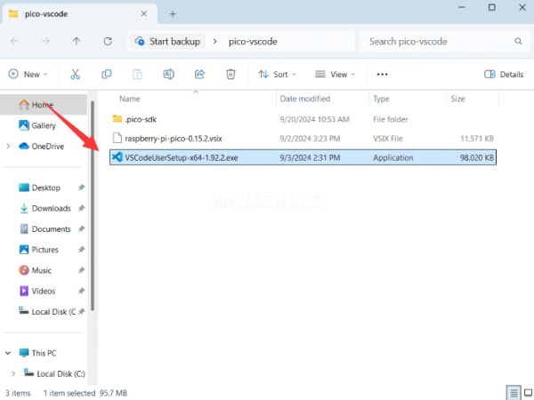
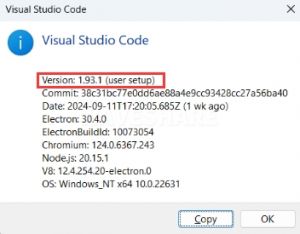
- First, click to download pico-vscode package, unzip and open the package, double-click to install VSCode
Note: If vscode is installed, check if the version is v1.87.0 or later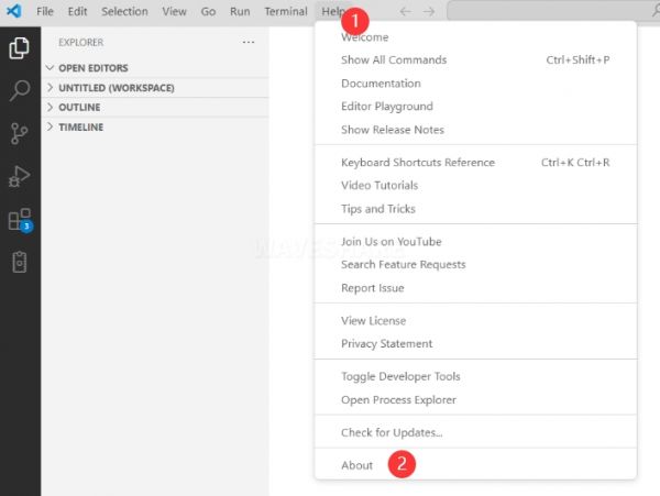
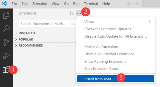
Install Extension
- Click Extensions and select Install from VSIX
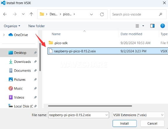
- Select the package with the vsix suffix and click Install
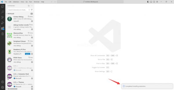
- Then vscode will automatically install raspberry-pi-pico and its dependency extensions, you can click Refresh to check the installation progress
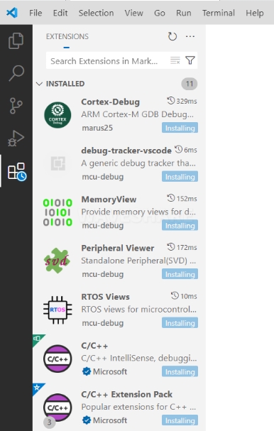
- The text in the right lower corner shows that the installation is complete. Close VSCode
Configure Extension
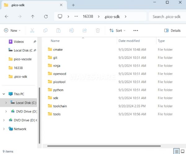
- Open directory C:\Users\username and copy the entire .pico-sdk to that directory
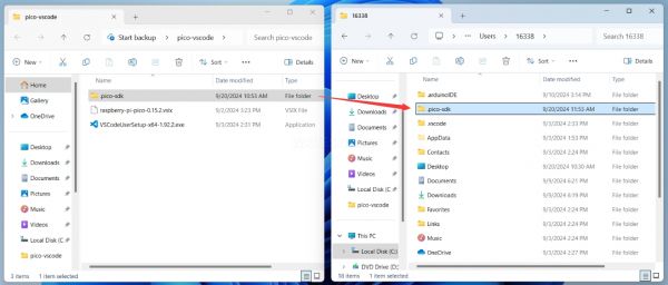
- The Copy is completed
- Open vscode and configure the paths for the Raspberry Pi Pico extensions
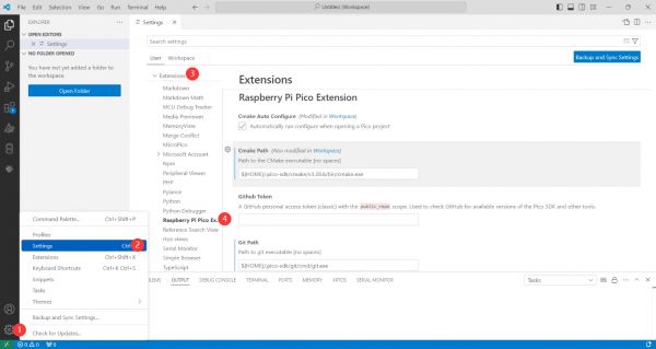
The configuration is as follows:Cmake Path: ${HOME}/.pico-sdk/cmake/v3.28.6/bin/cmake.exe Git Path: ${HOME}/.pico-sdk/git/cmd/git.exe Ninja Path: ${HOME}/.pico-sdk/ninja/v1.12.1/ninja.exe Python3 Path: ${HOME}/.pico-sdk/python/3.12.1/python.exe
New Project
- The configuration is complete, create a new project, enter the project name, select the path, and click Create to create the project
To test the official example, you can click on the Example next to the project name to select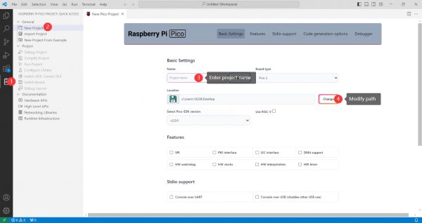
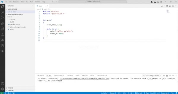
- The project is created successfully
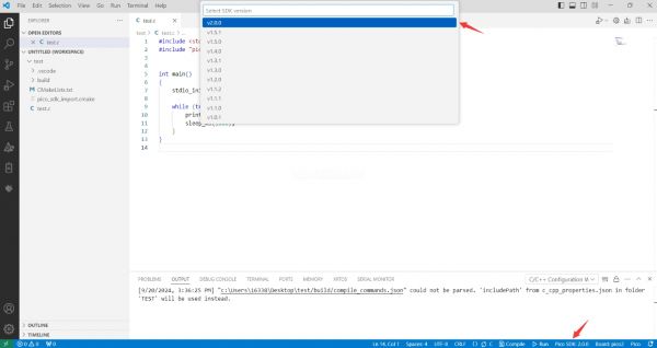
- Select the SDK version
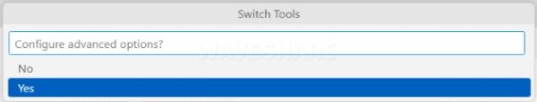
- Select Yes for advanced configuration
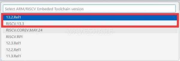
- Choose the cross-compilation chain, 13.2.Rel1 is applicable for ARM cores, RISCV.13.3 is applicable for RISCV cores. You can select either based on your requirements
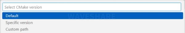
- Select default for CMake version (the path configured earlier)
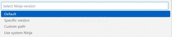
- Select default for Ninjaversion
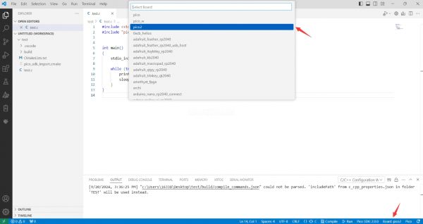
- Select the development board
- Click Complie to compile
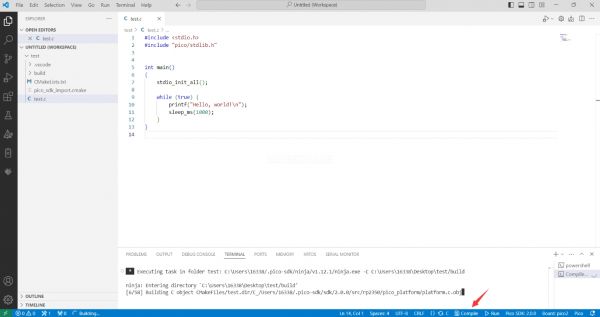
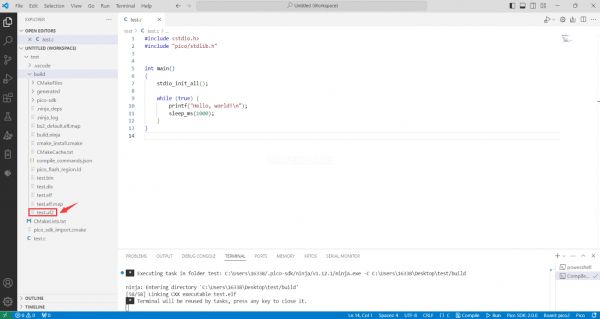
- The uf2 format file is successfully compiled
Import Project
- The Cmake file of the imported project cannot have Chinese (including comments), otherwise the import may fail
- To import your own project, you need to add a line of code to the Cmake file to switch between pico and pico2 normally, otherwise even if pico2 is selected, the compiled firmware will still be suitable for pico
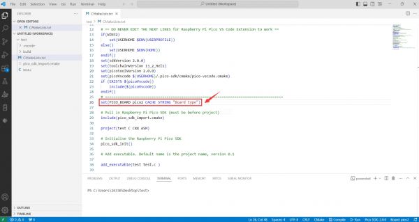
set(PICO_BOARD pico CACHE STRING "Board type")
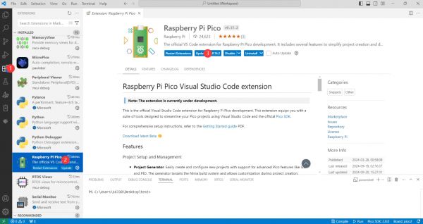
Update Extension
- The extension version in the offline package is 0.15.2, and you can also choose to update to the latest version after the installation is complete
Arduino IDE Series
Install Arduino IDE
- First, go to Arduino official website to download the installation package of the Arduino IDE.
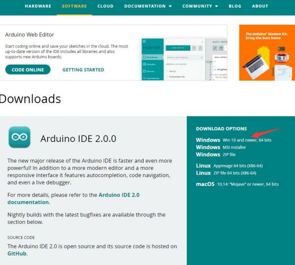
- Here, you can select Just Download.

- Once the download is complete, click Install.
Notice: During the installation process, it will prompt you to install the driver, just click Install
Arduino IDE Interface
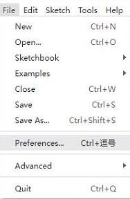
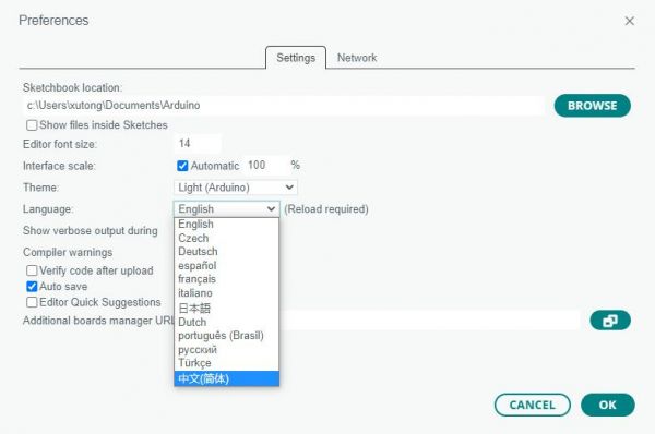
- After the first installation, when you open the Arduino IDE, it will be in English. You can switch to other languages in File --> Preferences, or continue using the English interface.
- In the Language field, select the language you want to switch to, and click OK.
Install Arduino-Pico Core in Arduino IDE
- Open the Arduino IDE, click on the file in the top left corner, and select Preferences

- Add the following link to the attached board manager URL, and then click OK
https://github.com/earlephilhower/arduino-pico/releases/download/4.0.2/package_rp2040_index.json
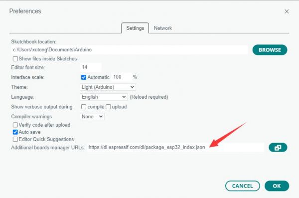
Note: If you already have an ESP32 board URL, you can use a comma to separate the URLs as follows:https://dl.espressif.com/dl/package_esp32_index.json,https://github.com/earlephilhower/arduino-pico/releases/download/4.0.2/package_rp2040_index.json
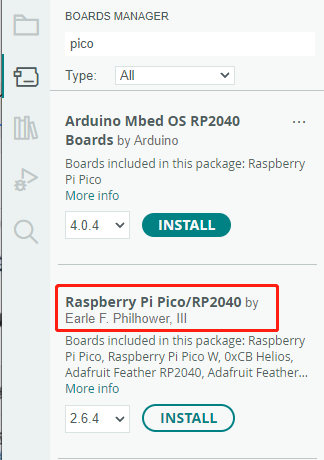
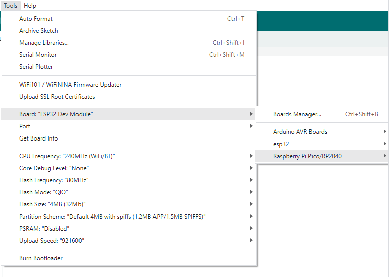
- Click Tools > Development Board > Board Manager > Search pico, as my computer has already been installed, it shows that it is installed
Upload Demo at the First Time
- Press and hold the BOOTSET button on the Pico board, connect the pico to the USB port of the computer via the Micro USB cable, and release the button after the computer recognizes a removable hard disk (RPI-RP2).
- Download the program and open D1-LED.ino under the arduino\PWM\D1-LED path
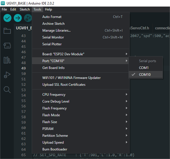
- Click Tools --> Port, remember the existing COM, do not click this COM (the COM displayed is different on different computers, remember the COM on your own computer)
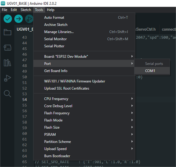
- Connect the driver board to the computer using a USB cable. Then, go to Tools > Port. For the first connection, select uf2 Board. After uploading, when you connect again, an additional COM port will appear
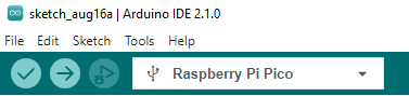
- Click Tools > Development Board > Raspberry Pi Pico > Raspberry Pi Pico or Raspberry Pi Pico 2
- After setting it up, click the right arrow to upload the program
- If issues arise during this period, and if you need to reinstall or update the Arduino IDE version, it is necessary to uninstall the Arduino IDE completely. After uninstalling the software, you need to manually delete all contents within the C:\Users\[name]\AppData\Local\Arduino15 folder (you need to show hidden files to see this folder). Then, proceed with a fresh installation.
Open Source Demos
MircoPython video demo (github)
MicroPython firmware/Blink demos (C)
Raspberry Pi official C/C++ demo (github)
Raspberry Pi official micropython demo (github)
Arduino official C/C++ demo (github)
Demo
Working with C
Directory Structure
├── CMakeLists.txt
├── example_auto_set_url.cmake
├── examples # Demos
│   ├── CMakeLists.txt
│   ├── amoled # Demo of testing AMOLED
│   │   ├── CMakeLists.txt
│   │   ├── amoled_flush_rgb
│   │   └── amoled_touch
│   ├── battery_read # Demo of serial port printing battery voltage
│   ├── hello_world # Demo of printing hello world
│   │   ├── CMakeLists.txt
│   │   ├── serial
│   │   └── usb
│   ├── lvgl # Demos using LVGL
│   │   ├── CMakeLists.txt
│   │   ├── factory # Pre-installed demo
│   │   ├── lv_port # Source files for LVGL hardware integration
│   │   ├── lvgl_battery # Demo of using LVGL to display battery voltage value
│   │   ├── lvgl_brightness # Demo of using LVGL to control screen brightness
│   │   ├── lvgl_example # Demo of running LVGL's own demo
│   │   ├── lvgl_image #Demo of using LVGL to display images
│   │   ├── lvgl_pcf85063 # Demo of using LVGL to display time and date
│   │   └── lvgl_qmi8658 # Demo of using LVGL to display IMU data
│   ├── qmi8658_raw_out # Demo of using serial port to print IMU data
│   ├── rtc_pcf85063 # Demo of using serial port to print time and date
│   └── sd_card_spi # Demo for testing SD Card read and write
├── firmware # Compiled firmware
├── libraries # Library files
│   ├── CMakeLists.txt
│   ├── bsp # Hardware-related libraries
│   ├── lvgl # LVGL library
│   └── no-OS-FatFS-SD-SDIO-SPI-RPi-Pico # TF Card related libraries
├── pico_extras_import_optional.cmake
└── pico_sdk_import.cmake
Compile
If Using the VSCode Raspberry Pi Pico Plugin
- Import project, and select project directory
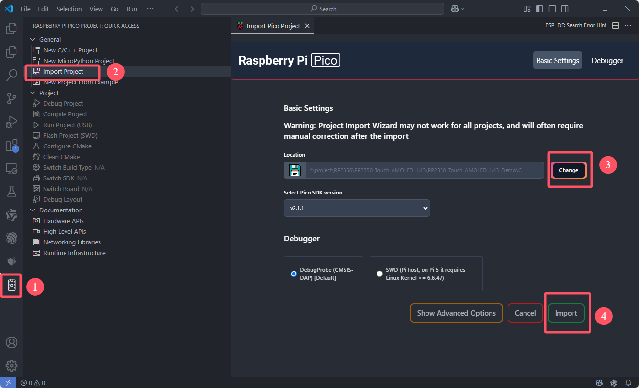
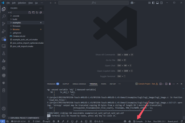
- Click Comple to compile
If using Ubuntu
cd RP2350-Touch-AMOLED-1.43-Demo/C
mkdir build
cd build
cmake ..
make -j8
Compiled Firmware
- After compilation, a .uf2 file will be generated in the build/examples directory
Flash Firmware
- Press and hold the BOOT button on the board, connect the board to the USB port of the computer through the Type-C cable, then release the button. The computer will recognize it as a removable drive, and finally copy the compiled .uf2 format file to the removable drive.
New Project
- Let's take the example of creating a new project named lvgl_test.
- Create a new folder lvgl_test in the examples/lvgl directory and create new CMakeLists.txt and main.c files in this folder.
- The content of the CMakeLists.txt file is
add_executable(lvgl_test
    main.c
    ../lv_port/lv_port.c
    )

pico_enable_stdio_usb(lvgl_test 1)
pico_enable_stdio_uart(lvgl_test 0)

# pull in common dependencies
target_link_libraries(lvgl_test
    pico_stdlib
    bsp
    lvgl
    lvgl::demos)

# create map/bin/hex/uf2 file etc.
pico_add_extra_outputs(lvgl_test)
- The content of the main.c file is
#include <stdio.h>
#include "pico/stdlib.h"
#include "../lv_port/lv_port_disp.h"
#include "../lv_port/lv_port_indev.h"
#include "demos/lv_demos.h"
#include "bsp_i2c.h"

#include "hardware/pll.h"
#include "hardware/clocks.h"
#include "hardware/structs/pll.h"
#include "hardware/structs/clocks.h"
#define LVGL_TICK_PERIOD_MS 1

#define DISP_HOR_RES 466
#define DISP_VER_RES 466

void set_cpu_clock(uint32_t freq_Mhz)
{
    set_sys_clock_hz(freq_Mhz * MHZ, true);
    clock_configure(
        clk_peri,
        0,
        CLOCKS_CLK_PERI_CTRL_AUXSRC_VALUE_CLKSRC_PLL_SYS,
        freq_Mhz * MHZ,
        freq_Mhz * MHZ);
}


static bool repeating_lvgl_timer_cb(struct repeating_timer *t)
{
    lv_tick_inc(LVGL_TICK_PERIOD_MS);
    return true;
}

int main()
{
    stdio_init_all();
    set_cpu_clock(250);
    bsp_i2c_init();

    lv_init();
    lv_port_disp_init(DISP_HOR_RES, DISP_VER_RES, 0, false);
    lv_port_indev_init(DISP_HOR_RES, DISP_VER_RES, 0);
    static struct repeating_timer lvgl_timer;
    add_repeating_timer_ms(LVGL_TICK_PERIOD_MS, repeating_lvgl_timer_cb, NULL, &lvgl_timer);
    lv_demo_widgets();
    // lv_demo_music();
    while (true)
    {
        lv_timer_handler();
        sleep_ms(LVGL_TICK_PERIOD_MS);
    }
}
- Add at the end of CMakeLists.txt in the examples/lvgl directory.
add_subdirectory(${CMAKE_CURRENT_LIST_DIR}/lvgl_test)
- Recompile, build/examples/lvgl will add a new folder lvgl_test, which contains the compiled and generated .uf2 files.
Working with MicroPython
Directory Structure
├── examples
│   ├── imu_test.py # Demo of printing IMU data
│   ├── oled_test.py # Demo of testing AMOLED
│   ├── oled_touch.py # Demo of testing AMOLED and touch simultaneously
│   ├── rtc_test.py # Demo of printing time and date
│   └── touch_test.py # Demo of testing touch, printing coordinates
├── firmware
│   └── RP2350-Touch-AMOLED-1.43.uf2 # MicroPython firmware
└── libraries
    ├── amoled_1inch43.py # 1.43-inch screen related driver, including display and touch
    ├── imu.py # IMU-related driver
    └── rtc.py # RTC-related driver
Flash Firmware
- Press and hold the BOOT button on the board, connect the board to the USB port of the computer through the Type-C cable, then release the button. The computer will recognize it as a removable drive, and finally copy the firmware/RP2350-Touch-AMOLED-1.43.uf2 file to the removable drive.
Upload Libraries
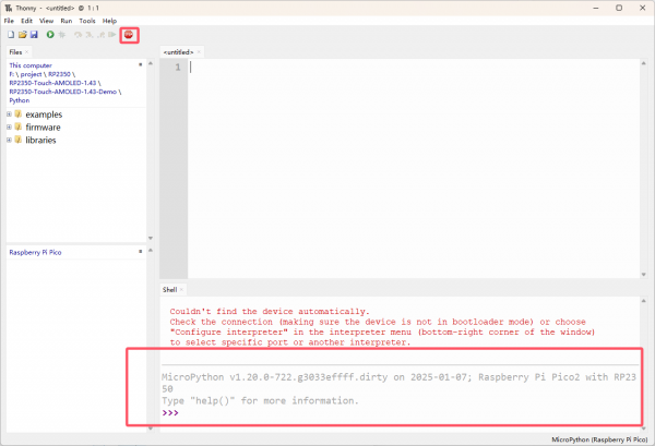
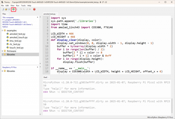
- Open Thonny, click Stop/Restart backend, if the shell below shows the information in the picture, it means the board is connected successfully.
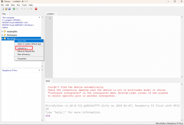
- Select libraries, right-click ->Upload to /, and wait for the upload to complete
Run
- Open any .py in the examples, click Run current script, and the program will start running
Resources
Supporting Resources
Demo
Schematic Diagram
Datasheets
Official Resources
Raspberry Pi Official Documents
- Get Started with MicroPython on Raspberry Pi Pico
- Raspberry Pi related books download
- Pico2 Schematic diagram
- Pico2 Pinout definition
- Pico2 Getting Started
- Pico2 C SDK User Manual
- Pico2 Python SDK User Manual
- Pico2 Datasheet
- RP2350 Datasheet
- RP2350 Hardware Design Reference Manual
Raspberry Pi Open Source Demos
Development Softwares
FAQ
Question: What is the spacing of 2×7 on both sides?
1.27mm
Support
Monday-Friday (9:30-6:30) Saturday (9:30-5:30)
Email: services01@spotpear.com

[Tutorial Navigation]
- Overview
- MicroPython Series Tutorials
- 【MicroPython】 Machine.Pin Functions
- 【MicroPython】machine.PWM Function
- 【MicroPython】machine.ADC Function
- 【MicroPython】machine.UART Function
- 【MicroPython】machine.I2C Function
- 【MicroPython】machine.SPI Function
- 【MicroPython】PIO Function
- Demo
- Resources
- FAQ
- Support