- sales/support
Google Chat:---
- sales
+86-0755-88291180
- sales01
sales@spotpear.com
- sales02
dragon_manager@163.com
- support
tech-support@spotpear.com
- CEO-Complaints
zhoujie@spotpear.com
- Only Tech-Support
WhatsApp:13246739196
- Purchase/Shipping/Refund
WhatsApp:13424403025
- HOME
- >
- ARTICLES
- >
- Common Moudle
- >
- LCD
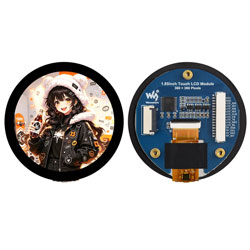
1.85inch Touch LCD Module User Guide
Features
- 360 × 360 resolution, supporting 262K color display
- IPS display panel with capacitive touch
- Built-in ST77916 display driver chip and CST816S capacitive touch controller
- Display via QSPI interface, touch via I2C interface
- Onboard level shifter chip, compatible with 3.3V / 5V power input
- Supports 15PIN terminal interface or 18PIN FPC slot
Specifications
| Parameter | Specification |
|---|---|
| Operating Voltage | 3.3 V / 5 V |
| Resolution | 360 × 360 pixels |
| Display Driver | ST77916 |
| Touch Chip | CST816S |
| Display Interface | QSPI |
| Touch Interface | I2C |
| Display Panel | IPS |
| Touch Type | Capacitive |
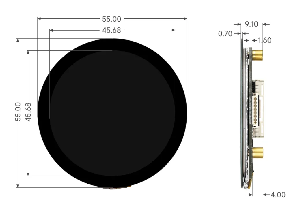
| Display Area | 45.68 × 45.68 mm |
| Display Color | 262K |
| Brightness | 450 cd/m² |
| Contrast Ratio | 1200:1 |
| Product Dimensions | 55 × 55 mm |
Interface Description
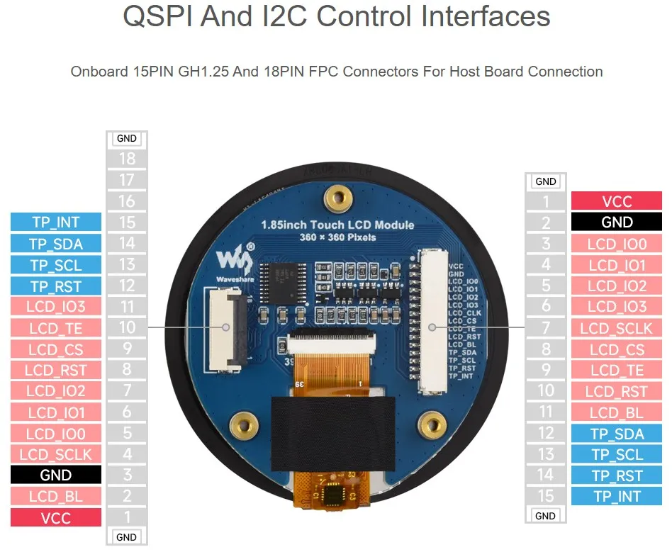
| Function Pin | Description | 15PIN Number | 18PIN Number |
|---|---|---|---|
| VCC | Power positive (3.3 V / 5 V input) | 1 | 1 |
| GND | Power ground | 2 | 3 |
| LCD_IO0 | QSPI data signal pin 0 | 3 | 5 |
| LCD_IO1 | QSPI data signal pin 1 | 4 | 6 |
| LCD_IO2 | QSPI data signal pin 2 | 5 | 7 |
| LCD_IO3 | QSPI data signal pin 3 | 6 | 11 |
| LCD_SCLK | QSPI clock signal pin | 7 | 4 |
| LCD_CS | LCD chip select, active low | 8 | 9 |
| LCD_TE | LCD tearing effect synchronization signal | 9 | 10 |
| LCD_RST | LCD reset pin, active low | 10 | 8 |
| LCD_BL | LCD backlight pin | 11 | 2 |
| TP_SDA | Touch data pin | 12 | 14 |
| TP_SCL | Touch clock pin | 13 | 13 |
| TP_RST | Touch reset pin, active low | 14 | 12 |
| TP_INT | Touch interrupt pin | 15 | 15 |
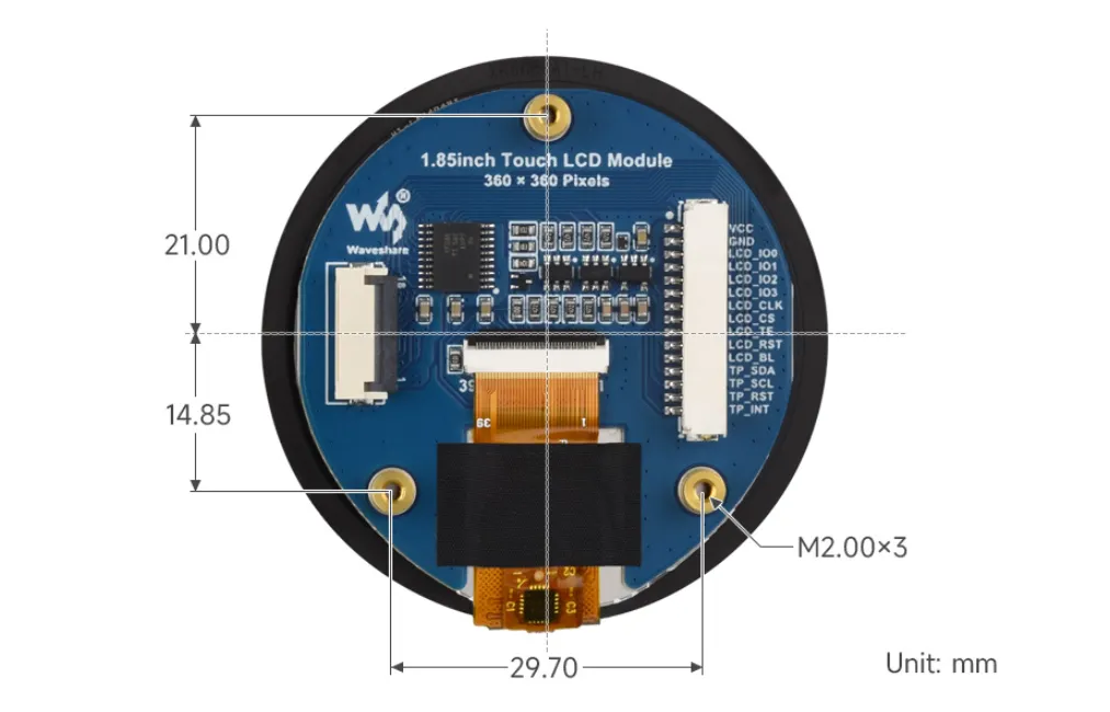
Dimensions
ESP-IDF
This chapter contains the following sections. Please read as needed:
ESP-IDF Getting Started
New to ESP32 ESP-IDF development and looking to get started quickly? We have prepared a general Getting Started Tutorial for you.
- Section 1: Environment Setup
- Section 2: Running Examples
- Section 3: Creating a Project
- Section 4: Using Components
- Section 5: Debugging
- Section 6: FreeRTOS
- Section 7: Peripherals
- Section 8: Wi-Fi Programming
- Section 9: BLE Programming
Please Note: This tutorial uses the ESP32-S3-Zero as a teaching example, and all hardware code is based on its pinout. Before you start, it is recommended that you check the pinout of your development board to ensure the pin configuration is correct.
Setting Up the Development Environment
The following guide uses Windows as an example, demonstrating development using VS Code + the ESP-IDF extension. macOS and Linux users should refer to the official documentation.
The screenshots in this section use ESP-IDF V5.5.2 as an example. When installing, please select the ESP-IDF version that matches your board's example.
Install the ESP-IDF Development Environment
Download the installation manager from the ESP-IDF Installation Manager page. This is Espressif's latest cross-platform installer. The following steps demonstrate how to use its offline installation feature.
Click the Offline Installer tab on the page, then select Windows as the operating system and the ESP-IDF version you need (the version shown in the screenshot is for reference only — choose the version that fits your actual needs).
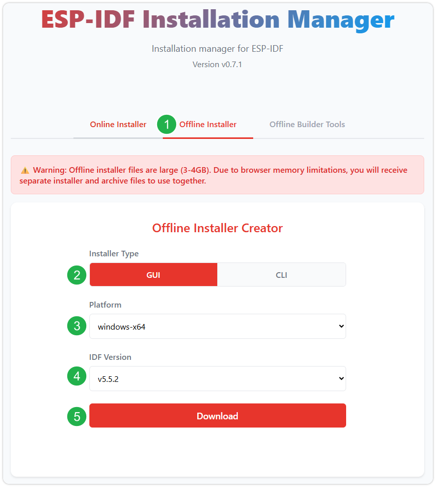
After confirming your selection, click the download button. The browser will automatically download two files: the ESP-IDF Offline Package (.zst) and the ESP-IDF Installer (.exe).
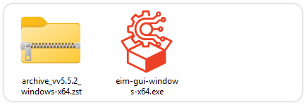
Please wait for both files to finish downloading.
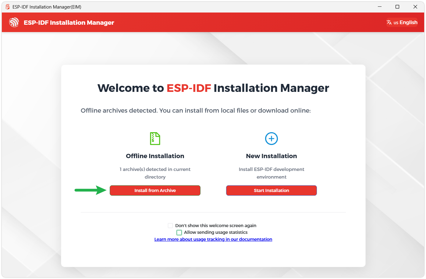
Once the download is complete, double-click to run the ESP-IDF Installer (eim-gui-windows-x64.exe).
The installer will automatically detect if the offline package exists in the same directory. Click Install from archive.
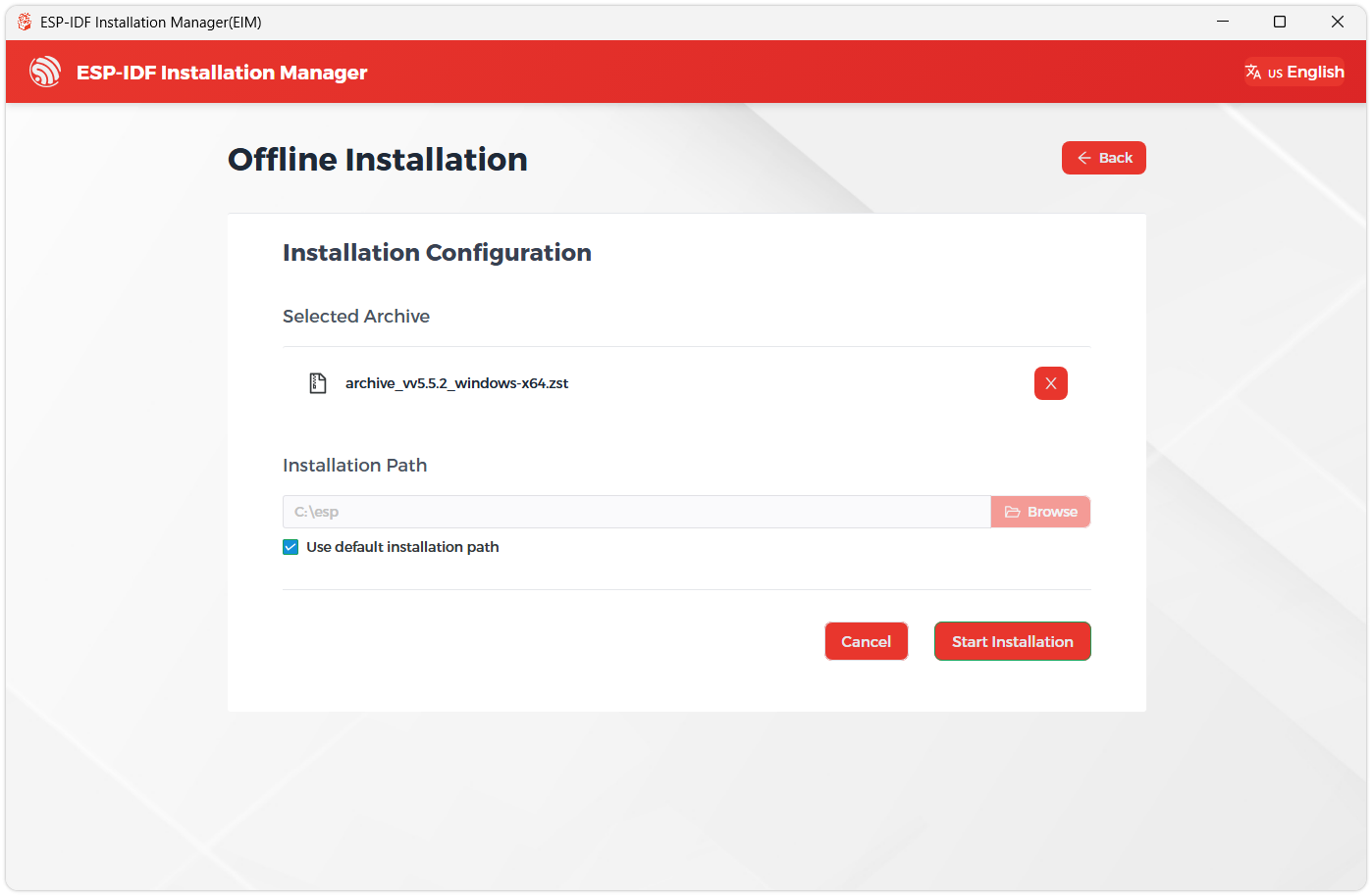
Next, select the installation path. We recommend using the default path. If you need to customize it, ensure the path does not contain Chinese characters or spaces. Click Start installation to proceed.
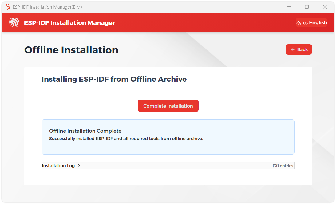
When you see the following screen, the ESP-IDF installation is successful.
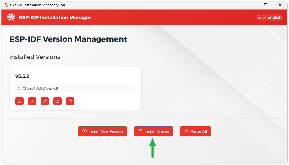
We recommend installing the drivers as well. Click Finish installation, then select Install driver.
Install Visual Studio Code and the ESP-IDF Extension
Download and install Visual Studio Code.
During installation, it is recommended to check Add "Open with Code" action to Windows Explorer file context menu to facilitate opening project folders quickly.
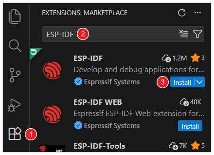
In VS Code, click the Extensions icon
 in the Activity Bar on the side (or use the shortcut Ctrl + Shift + X) to open the Extensions view.
Enter ESP-IDF in the search box, locate the ESP-IDF extension, and click Install.
For ESP-IDF extension versions ≥ 2.0, the extension will automatically detect and recognize the ESP-IDF environment installed in the previous steps, requiring no manual configuration.
Example
This module provides the following two ESP-IDF examples, both based on LVGL 8.3. Choose the appropriate example based on the connector used on the module and the development board: 1.85-S3-test is for the 15PIN GH connector with DuPont wires, and 1.85-S3-audio-board-test is for the 18PIN FFC connector with an FFC cable.
1.85-S3-test
Example Description
- Suitable for the module's 15PIN GH connector, connected to the ESP32-S3-DEV-KIT-N16R8-M development board via GH-to-Dupont wires.
- Initializes QSPI display, I2C touch, and the LVGL graphics library.
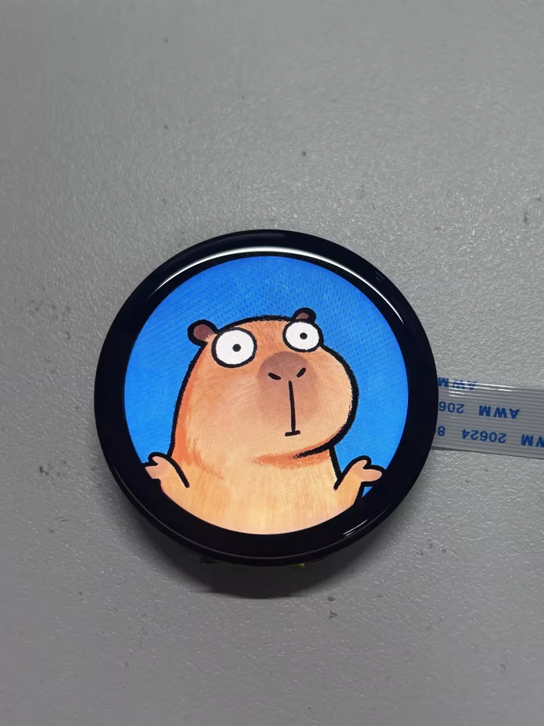
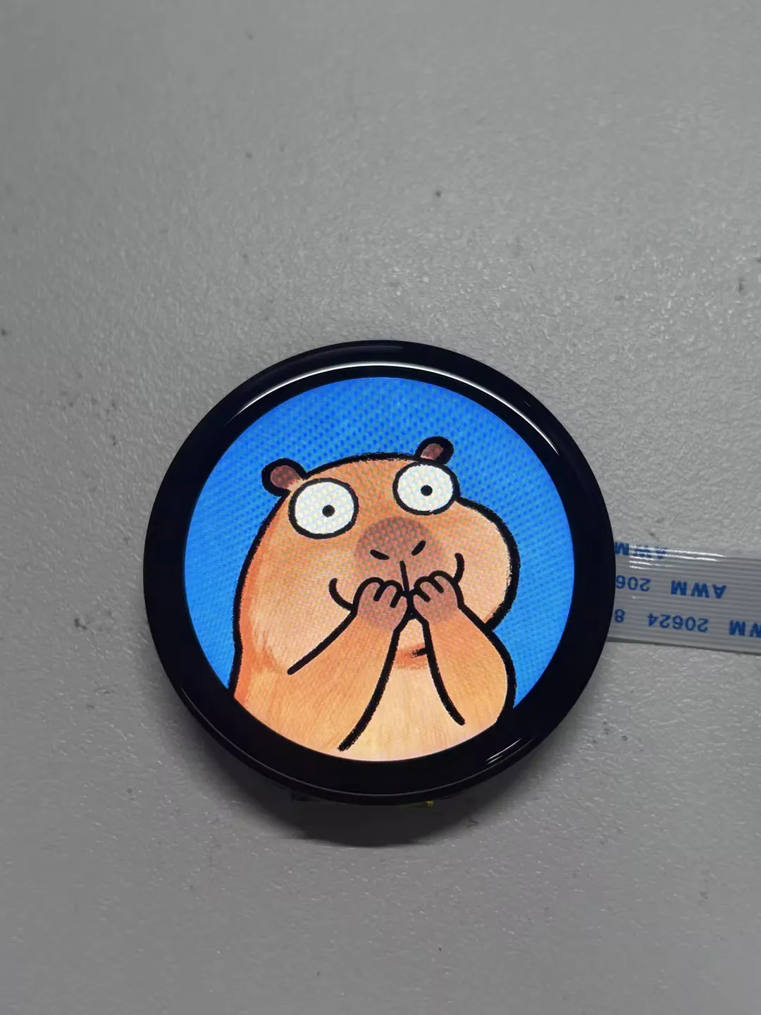
- The screen displays two 360 × 360 images that can be switched by swiping left or right, serving as a reference for LVGL image display and touch gesture development.
Hardware Connection
Use a 15PIN GH-to-Dupont wire cable and connect the display module to the ESP32-S3 development board as shown in the table below:
| 1.85inch Touch LCD Module | ESP32-S3-DEV-KIT-N16R8-M |
|---|---|
| VCC | 3.3 V |
| GND | GND |
| LCD_IO0 | GPIO 9 |
| LCD_IO1 | GPIO 8 |
| LCD_IO2 | GPIO 7 |
| LCD_IO3 | GPIO 6 |
| LCD_SCLK | GPIO 4 |
| LCD_CS | GPIO 3 |
| LCD_TE | GPIO 18 |
| LCD_RST | NC |
| LCD_BL | GPIO 5 |
| TP_SDA | GPIO 11 |
| TP_SCL | GPIO 10 |
| TP_RST | NC |
| TP_INT | NC |
- After verifying the connections, connect the development board to the computer.
Code Analysis
image_swipe_page_create(): Creates a full-screen image page, loads two images, and registers gesture events.image_gesture_cb(): Detects left and right swipe gestures and cycles between images by showing or hiding the image objects.app_main(): Initializes the display, touch, and LVGL in sequence, then continuously calls the LVGL timer handler function.
Operation Result
1.85-S3-audio-board-test
Example Description
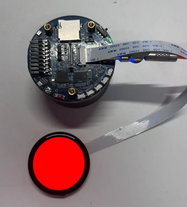
- Suitable for the module's 18PIN FFC connector, connected to the ESP32-S3-AUDIO-Board via an FFC cable.
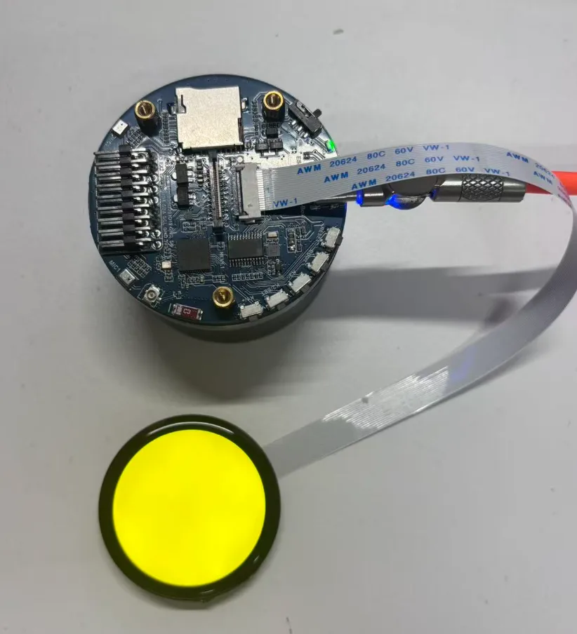
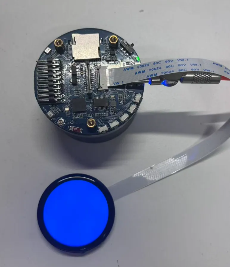
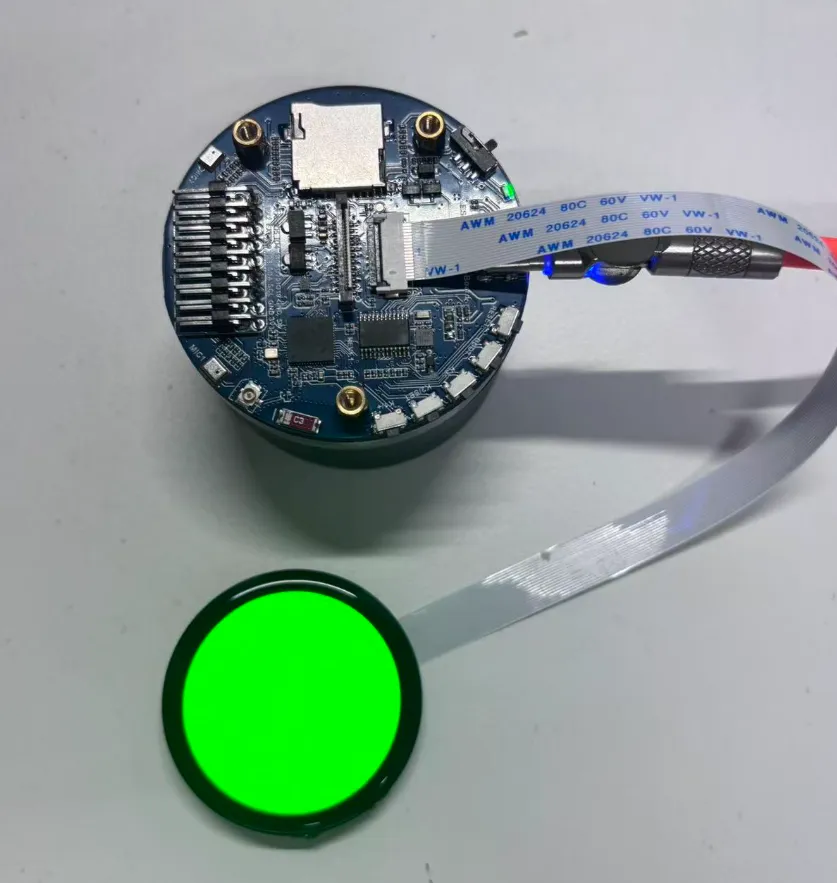
- Upon power-on, the screen displays solid color screens in red, green, blue, and yellow sequentially to verify LCD display and color reproduction.
- After the color test, the LVGL Widgets example runs to verify LVGL rendering and touch interaction.
- The project includes a
lv_demo_music()call entry; you can switch to the LVGL example inmain.cif needed.
Hardware Connection
- Use an 18PIN FFC cable to connect the display module to the ESP32-S3-AUDIO-Board; no need to connect individual Dupont wires.
- Connect and disconnect the FFC cable only when the board is powered off. Ensure the cable is fully inserted before powering on the development board.
Code Analysis
main_page_red(),main_page_green(),main_page_blue(),main_page_yellow(): Set the background color of the LVGL active screen to implement solid color display tests.app_main(): Initializes LCD, touch, and LVGL. After completing the color test, launches the LVGL Widgets example.
Operation Result
Resources
1. Hardware Resources
2. Example
3. Software
4. Other Resources
- LVGL Online Image Converter
- LVGL Online Font Converter
- ESP32 Arduino Core Documentation
- arduino-esp32
- ESP-IDF
Support
Monday-Friday (9:30-6:30) Saturday (9:30-5:30)
Email: services01@spotpear.com