- sales/support
Google Chat:---
- sales
+86-0755-88291180
- sales01
sales@spotpear.com
- sales02
dragon_manager@163.com
- support
tech-support@spotpear.com
- CEO-Complaints
zhoujie@spotpear.com
- Only Tech-Support
WhatsApp:13246739196
- Purchase/Shipping/Refund
WhatsApp:13424403025
RS232-RS485-CAN-Board User Guide
Overview
Introduction
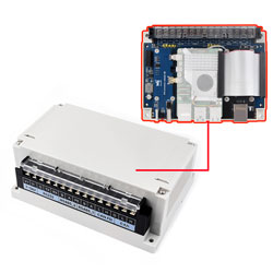
Are you still worried that Raspberry Pi can't be used in industrial environment? The isolated industrial interface expansion board is specially designed for Raspberry Pi 4B and Raspberry Pi 5! This industrial expansion board provides a variety of industrial communication interfaces for your Raspberry Pi: 2x RS485, 1x RS232, 1x CAN FD and 1x CAN, and each interface boasts electrical isolation protection. It provides stable communication with lightning-proof and anti-electrostatic protection and so on. Also, it comes with customized industrial rail-mount enclosure for easy integration in industrial control applications. For Raspberry Pi 5, it reserves PCIe interface for further expansion function, and provides sufficient internal space for users to stack and expand functions. This expansion board not only make your Raspberry Pi better integrated into industrial control applications, but also provide the possibility for future expansion.
Features
- Compatibility
- Compatible with Raspberry Pi 4B and Raspberry Pi 5 with standard Raspberry Pi 40pin GPIO headers.
- Multiple Industrial Communication Interfaces
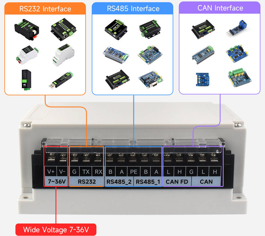
- Provide 2x RS485, 1x RS232, 1x CAN FD and 1x CAN communication interface
- Electrical Isolation Protection
- Each interface boasts electrical isolation, ensuring communication safety and reliability.
- Flexible Expandability
- Adopt SC16IS752 and SP485 dual chips, expand 2x RS485 interfaces through SPI interface.
- Adopt MCP2515 and SN65HVD230 dual chips, expand 1x CAB interface through SPI interface.
- Adopt MCP2518FD and MCP2562FD dual chips, expand 1x CAN FD interface.
- Adopt Raspberry UART and SP3232EEN dual chips, expand 1x RS232 through UART interface.
- Protection
- Onboard TVS (Transient Voltage Suppressor), lightningproof and ESD protection.
- Onboard self-recovery fuse and protection diodes, boasting anti-surge, over-voltage protection and improving anti-shock ability.
- Power Isolation
- Onboard unibody power isolation, no additional power supply, ensuring the stable current and voltage output of RS232, RS485, CAN, and CAN FD, with powerful anti-interference ability.
- Signal Isolation
- Onboard digital isolation chip, improving the safety, stability and anti-interference of signal isolation.
- Flexible Power Supply
- Support 7~36V wide voltage input and can work with Pi5 Connector Adapter (B) to power the Raspberry Pi and the HAT.
- Adjustable Terminal Resistor
- Onboard 120Ω terminal resistor, enable through jumper cap.
- Reserve Interrupt Resistor
- Reserve interrupt resistor pad, support flexible interrupt pin switching, avoid occupying special pins.
- Expansion and Installation
- Reserve PCIe connector for Raspberry Pi 5 for further function expansion.
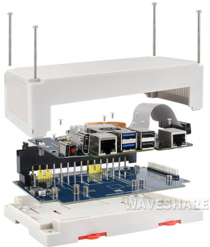
- Provide customized industrial rail-mount case, reserves enough internal space for stacking boards for customizable functions.
- Complete Resources
- Provide online development resources and manuals including Raspberry Python, C demos and so on.
Parameters
| Model | Industrial Isolated Interface Expansion Board for Raspberry Pi | |||
| Applicable Boards | Raspberry Pi 4B, Raspberry Pi 5 | |||
|---|---|---|---|---|
| Communication Interface | SPI + UART | |||
| Industrial Interface | ||||
| Interface Description | Chip Scheme | Baudrate | ||
| 1x Isolated CAN FD | MCP2518FD + MCP2562FD | 5kbps - 8 Mbps | ||
| 1x Isolated CAN | MCP2515 + SN65HVD230 | 5kbps - 1 Mbps | ||
| 2x Isolated RS485 | SC16IS752 + SP485 | 300 bps - 921600 bps | ||
| 1x Isolated RS232 | SP3232EEN | |||
| Expandability | Support Pi5 expands interfaces such as NVME, ETH, USB and 4G/5G through PCIe connector | |||
| Support Pi 4B/5 stack some HATs through 40PIN GPIO header (the pin and size must be consistent) | ||||
| Power Supply (optional) | Onboard 5V Type-C port | |||
| External screw terminal DC 7-36V wide voltage input | ||||
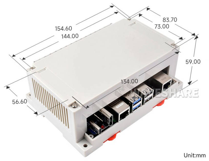
| Dimensions | 154.6 × 83.7 × 59 mm | |||
| Enclosure | Eco-friendly plastic case, support rail-mount and wall-mount installation | |||
Onboard Interface
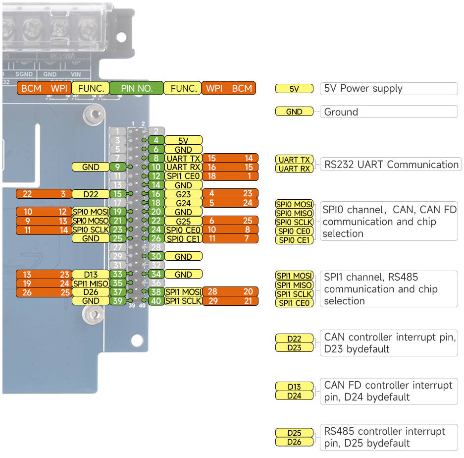
Pinout Definition
CAN Bus
The function of the CAN module is to handle the reception and transmission of all messages on the CAN bus. When a message is sent, the message is first loaded into the correct message buffer and control registers. A transmit operation can be initiated by setting the corresponding bit in the control register through the SPI interface or by using the transmit enable pin. Communication status and errors can be checked by reading the corresponding registers. Any message detected on the CAN bus is checked for errors and then matched against a user-defined filter to determine whether to move the message to one of two receive buffers.
Since the Raspberry Pi itself does not support the CAN bus, the CAN controller with the SPI interface is used with a transceiver to complete the CAN function.
Microchip's MCP2515 is a CAN protocol controller that fully supports the CAN V2.0B specification. The device can send and receive standard and extended data frames as well as remote frames. The MCP2515 comes with two acceptance mask registers and six acceptance filter registers to filter out unwanted messages, thus saving resources of the main microcontroller (MCU), which connects to the device via the SPI interface, i.e., the Raspberry Pi connects to the chip via the SPI interface, and the Raspberry Pi doesn't need to compile the driver but only needs to open the kernel driver in the device tree to use it. Support using with the MCP2518FD through one channel, only the chip selector pin is different!
The MCP2518FD is a CAN FD (Flexible Data Rate) controller produced by Microchip, which fully supports CAN framing in the Classic (CAN2.0) and CAN Flexible Data Rate (CAN FD) formats. The arbitration bit rate is as high as 1Mbps, the data baud rate also breaks through the 1Mbps limit of traditional CAN2.0, and the SPI clock speed is as high as 20MHz, which conforms to the ISO11898-1:2015 standard. The device can transmit and receive standard and extended data frames as well as remote frames. The MCP2518FD comes with 32 flexible filters and shielding objects that can filter out unwanted packets, thus reducing the overhead of the main microcontroller (MCU). The MCU is connected to the device through the SPI interface, that is, the Raspberry Pi is connected to the chip through the SPI interface. For the Raspberry Pi to use the chip, the device can be driven through the prepared device tree file. For more details, please refer to #Resource.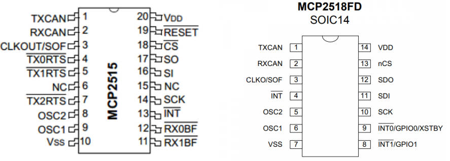
RS-485 Bus
Controller
This product adopts SC16IS752 as a controller. SC16IS752 is a high-performance UART expansion chip with dual channel support: SPI and I2C. This module adopts the SPI interface. Onboard power isolation, ADI magnetical isolation, onboard TVS (transient voltage suppression tube), self-recovery fuses and protection diodes and automatic transceiver conversion circuit. It can effectively suppress the surge voltage and transient spike voltage in the circuit, prevent lightning and static electricity, prevent overcurrent and overvoltage, improve the shock resistance, can be signal isolation, has the advantages of high reliability, strong anti-interference, low power consumption.
Communication Protocol
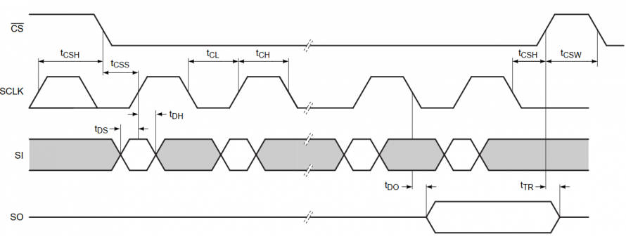
- CS: Slave chip selection, when CS is low, the slave chip is enabled.
- SCLK: SPI communication clock.
- MOSI/SI: SPI Communication host sends the data and the slave receives it.
- MOSI/SI: SPI Communication host receives the data and the slave sends it.
RS232 Bus
This product adopts SP3232 as a receiver. The SP3232E series are RS232 transceiver solutions intended for portable or hand-held applications such as notebook or palmtop computers. The SP3232E series has a high-efficiency, charge-pump power supply that requires only 0.1µF capacitors in 3.3V operation. This charge pump allows the SP3232E series to deliver true RS232 performance from a single power supply ranging from 3.0V to 5.5V. The SP3232E are 2-driver/2-receiver devices. During shutdown, the supply current falls to less than 1µA. For more details, you can refer to datasheet.
Dimensions
How to Assemble
Install Necessary Function Libraries
- Install BCM2835, open the Raspberry Pi terminal and run the following commands:
wget http://www.airspayce.com/mikem/bcm2835/bcm2835-1.60.tar.gz
tar zxvf bcm2835-1.60.tar.gz
cd bcm2835-1.60/
sudo ./configure
sudo make
sudo make check
sudo make install
#for more details, you can refer to http://www.airspayce.com/mikem/bcm2835/
wiringPi
32-bit Raspberry Pi System
#Open the Raspberry Pi terminal and run the following commands:
cd
sudo apt-get install wiringpi
#For Raspberry Pi systems after May 2019 (earlier may not support), upgrade may be required:
wget https://project-downloads.drogon.net/wiringpi-latest.deb
sudo dpkg -i wiringpi-latest.deb
gpio -v
#Running gpio -v and displays 2.52 version, if no, the installation is wrong

#For Bullseye branch system, you can run the following commands:
git clone https://github.com/WiringPi/WiringPi
cd WiringPi
./build
sudo gpio -v
#Running gpio -v and displays 2.70 version, if no, the installation is wrong
64-bit Raspberry Pi System
Use the command to copy the resource package to Raspberry Pi:
wget https://files.waveshare.com/upload/8/8c/WiringPi-master.zip
(Optional, you can skip this step if you have used the command to unzip it) Install environment to unzip
sudo apt-get install unzip
Enter the file path, and execute the command to unzip:
unzip WiringPi-master.zip
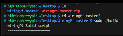
Enter the file directory (Enter the "WiringPi-master" file folder)
cd WiringPi-master/
Execute sudo ./build
sudo ./build
(Optional, see step 4 if it is error) If ". /build" does not work, run "chmod +x . /build" and then "sudo . /build".
chmod +x ./build
For example: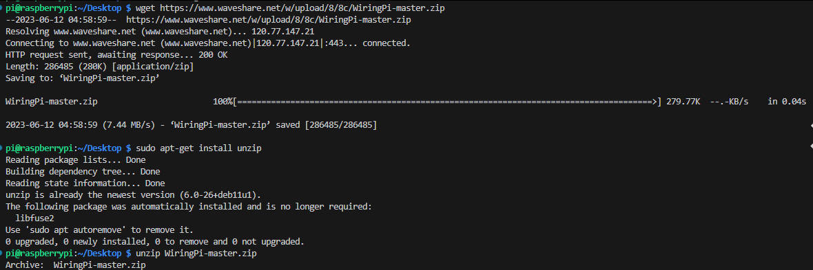
- Install Python function library:
#python2
sudo apt-get update
sudo apt-get install python-pip
sudo apt-get install python-pil
sudo apt-get install python-numpy
sudo pip install RPi.GPIO
sudo pip install spidev
sudo pip install python-can
#python3
sudo apt-get update
sudo apt-get install python3-pip
sudo apt-get install python3-pil
sudo apt-get install python3-numpy
sudo pip3 install RPi.GPIO
sudo pip3 install spidev
sudo pip3 install python-can
- Find the corresponding product on the official website, open the download path in the product information, and download the sample demo in the wiki:
- Get the unzipped package, unzip it and copy the demo to the Raspberry Pi.
Preparation
Enable Interface
Open the Raspberry PI terminal, execute the following command to enter the Raspberry Pi configuration:
sudo raspi-config
You need to disable the login shell and enable the serial port hardware.
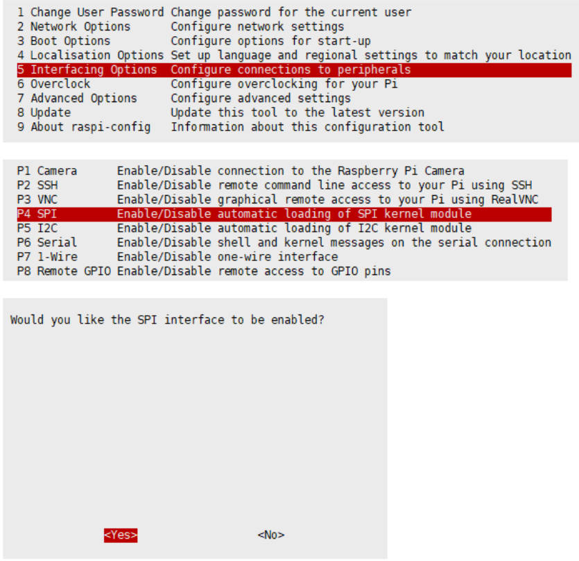
Choose Interfacing Options -> Serial -> No -> Yes:
Open the /boot/config.txt file and find the following configuration statement to enable the serial port, if not, add it at the end of the file:
enable_uart=1
- Select:
Interfacing Options -> SPI -> Yes to enable SPI interface
And reboot the Raspberry Pi:
sudo reboot
Please ensure the SPI does not be occupied by other devices, you can check it in /boot/config.txt.
Modify config.txt
Attach the module on the Raspberry Pi, and modify config.txt:
sudo nano /boot/config.txt #if you use Pi 5, please change it to /boot/firmwave/config.txt
Add the following commands at the last line:
dtparam=spi=on
dtoverlay=i2c0
dtoverlay=spi1-3cs
dtoverlay=sc16is752-spi1,int_pin=25
dtoverlay=mcp2515,spi0-0,oscillator=16000000,interrupt=23
dtoverlay=mcp251xfd,spi0-1,interrupt=24
- Reboot the Raspberry Pi to apply all settings:
sudo reboot
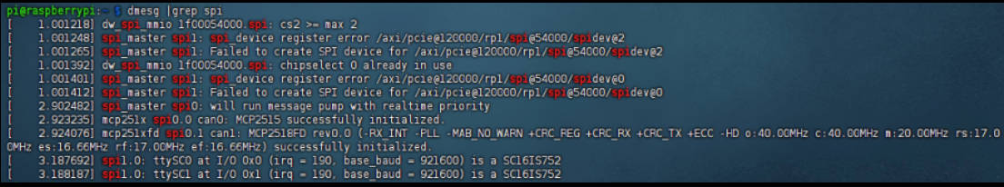
- After resetting the Raspberry Pi, view the SPI information:
dmesg | grep spi1
- Open CAN:
sudo ip link set can0 up type can bitrate 1000000
sudo ip link set can1 up type can bitrate 1000000
sudo ifconfig can0 txqueuelen 65536
sudo ifconfig can1 txqueuelen 65536
- For more CAN kernel commands, you can refer to:
https://www.kernel.org/doc/Documentation/networking/can.txt
- View ifconfig:
ifconfig
- Turn off the CAN device:
sudo ifconfig can0 down
sudo ifconfig can1 down
CAN Bus Demo
- Browse the directory.
- The receiver runs receive.py:
sudo python reveive.py
- The sender runs send.py:
sudo python send.py
Please note that the sender is sent using CAN1, and the receiver is CAN0. For more details, you can refer to the demo below:
Demo Description
【Python Demo】
This demo is based on Python platform, please ensure the "python-can" library is installed.
Please create a can device before sending as it only enables the MCP2515 kernel.
os.system('sudo ip link set can0 type can bitrate 100000')
os.system('sudo ifconfig can0 up')
The above command is initialized and enabled by configuring CAN0 and specifying CAN0 as the transmit/receive interface. To change to CAN1, the code is as follows:
os.system('sudo ip link set can1 type can bitrate 100000')
os.system('sudo ifconfig can1 up')
Step 1: Connect to CAN Bus
can0 = can.interface.Bus(channel = 'can0', bustyp = 'socketcan_ctypes')
- It must be modified as CAN1, and the demo as shown below:
can0 = can.interface.Bus(channel = 'can1', bustyp = 'socketcan')
Step 2: Create Messages
msg = can.Message(arbitration_id=0x123, data=[0, 1, 2, 3, 4, 5, 6, 7], extended_id=False)
Step 3: Send Messages
can0.send(msg)
- It must be modified as CAN1, and the demo is shown below:
can1.send(msg)
- Finally, the can device must be turned off.
os.system('sudo ifconfig can0 down')
- It must be modified as CAN1, and the demo as shown below:
os.system('sudo ifconfig can1 down')
- Receives data:
msg = can0.recv(10.0)
recv() defines the timeout receive time.
For more details, you can refer to https://python-can.readthedocs.io/en/stable/interfaces/socketcan.html
【WringPi Demo】
- Blocking reception, the Raspberry Pi opens a terminal and runs:
cd 2-CH_CAN_HAT_Code/wiringPi/receive/
make clean
sudo make
sudo ./can_receive
- Send, the Raspberry Pi opens a terminal and runs:
cd 2-CH_CAN_HAT_Code/ wiringPi/receive/
make clean
sudo make
sudo ./can_send
RS-485 Bus Demo
- Download and run the test demo:
sudo apt-get install p7zip-full
wget https://files.waveshare.com/upload/4/44/2-CH_RS485_HAT_code.7z
7z x 2-CH_RS485_HAT_code.7z
sudo chmod 777 -R  2-CH_RS485_HAT
cd 2-CH_RS485_HAT/
- In addition, you can download the project from Github:
sudo git clone https://github.com/waveshare/2-CH-RS485-HAT
cd 2-CH-RS485-HAT/
*Please note that the directory may be different.
- C demo:
cd c
make clean
make
sudo ./main
- PYTHON demo:
cd python
cd examples
sudo python3 main.py
#or
sudo python3 test.py
RS-232 Bus
It is easier to use RS-232: open the Raspberry Pi UART function, and it can be used directly after /dev/ttyAMA0 as a serial port communication.