- sales/support
Google Chat:---
- sales
+86-0755-88291180
- sales01
sales@spotpear.com
- sales02
dragon_manager@163.com
- support
tech-support@spotpear.com
- CEO-Complaints
zhoujie@spotpear.com
- Only Tech-Support
WhatsApp:13246739196
- Purchase/Shipping/Refund
WhatsApp:13424403025
- HOME
- >
- ARTICLES
- >
- Common Moudle
- >
- USB HUB
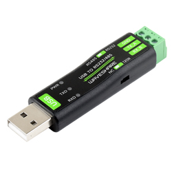
USB-TO-RS232-485 User Guide
Overview
USB TO RS232/485 is a USB to RS232/485 non-isolated serial port converter, featuring the original FT232RNL chip for improved stability and compatibility. It comes with a built-in self-recovering fuse, TVS protection circuit, etc. USB TO RS232/485 offers simple operation, zero-delay automatic transmission and reception conversion, and boasts characteristics such as fast, stable, reliable and safe communication.
Features
- Onboard Original FT232RNL chip. Fast communication, stable and reliable, better compatibility.
- Onboard TVS (Transient Voltage Suppressor), effectively suppresses surge voltage and transient spike voltage in the circuit, lightning-proof & anti-electrostatic.
- Onboard self-recovery fuse and protection diodes, ensure the current/voltage stable outputs, provide over-current/over-voltage proof, and improve shockproof performance.
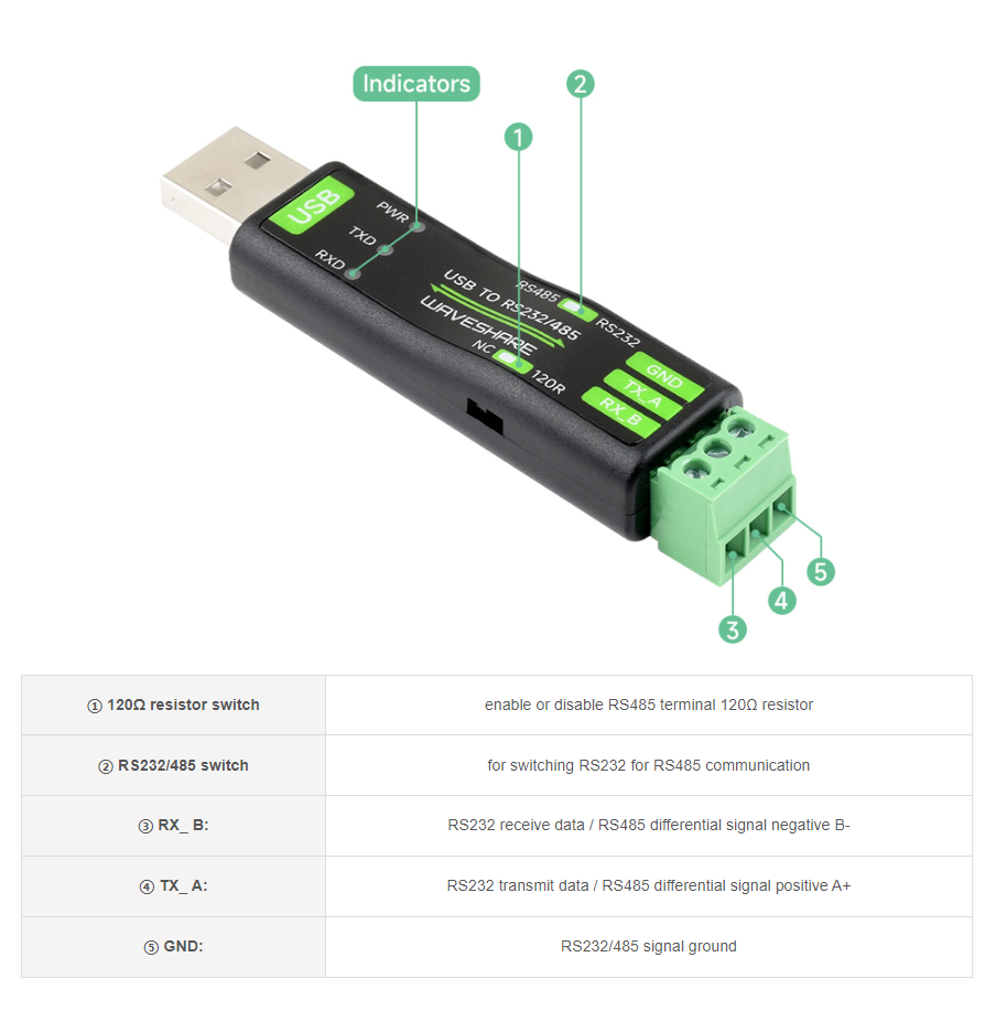
- Onboard RS232/485 communication switching circuit, configured by switch.
- Onboard 120R terminal resistor on the RS485 interface, enabled/disabled via switch.
- 3x LEDs for indicating the power and transceiver status.
- ABS case design, small in size, easy to use, portable and cost-effective.
Parameters
| Model | USB to RS232/RS485 | |
| Host Interface | USB | |
| Device Interface | RS232/RS485 | |
| USB Interface | Operating Level | 5V |
| Interface | Type-A male | |
| Protection | 200mA self-recovery fuse | |
| Transmission Distance | About 5m | |
| RS232 Interface | Interface | Screw Terminal |
| Transmission Distance | About 15m | |
| Transmission Mode | Point to Point | |
| Baud Rate | 300 bps ~ 921600bps | |
| RS485 Interface | Interface | Screw Terminal |
| Direction Control | Hardware automatic control | |
| Protection | Provide TVS diode protection, anti-surge, and ESD protection (onboard 120R resistor) | |
| Transmission Distance | About 1200m (at low rate) | |
| Transmission Mode | Point to multi-point (up to 32 nodes, add the relay for up to 16 nodes) | |
| Baudrate | 300 bps ~ 921600bps | |
| Indicator | PWR | Red power indicator, connect to USB, light on when the voltage is detected |
| TXD | Transmitting indicator, green light is on when data is sent from the USB interface | |
| RXD | Receiving indicator, blue light is on when the data is sent back from the device interface | |
| Usage Environment | Temperature Range | -15℃ ~ 70℃ |
| Humidity Range | 5% ~ 95%RH | |
| OS | Mac, Linux, Android, Windows 11 / 10 / 8.1 / 8 / 7 | |
Onboard Interface
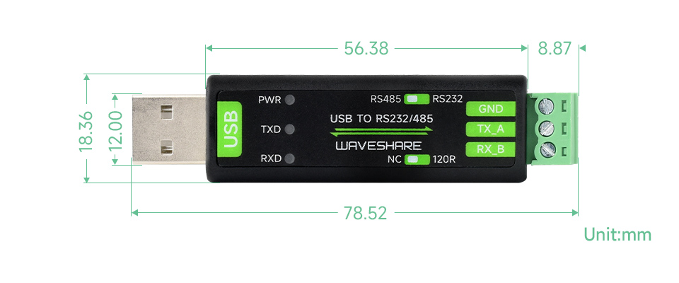
Dimensions
Driver Installation
USB Driver Installation
- Download the VCP Driver.
- Double click on CDM212364_Setup.exe and install it.
- Click on Extract, and then "NEXT".
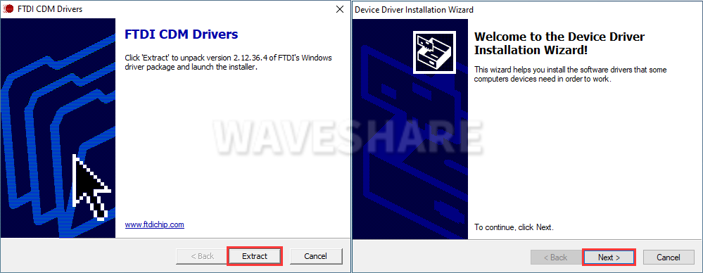
- Click on I accept this agreement, and then click on "NEXT", and click on "Finish".
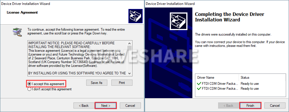
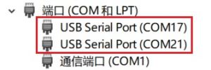
- After connecting the PC, you can see the usable COM port number in the device manager.
Hardware Test
Test environment: PC (Windows)
Required accessories:
- USB TO RS232/485 x 2pcs
- USB-A male-to-female cable x 1 (or directly connect to the USB port of the computer)
- Wires
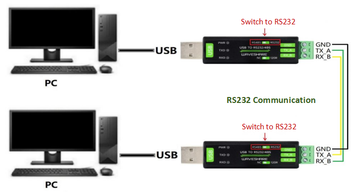
RS232 Test
- Connect the RS232 interface of the USB TO RS232/485 module to the RS232 interface, that is, RXD and TXD are connected in a staggered manner, GND and GND are connected, and the toggle switch on top of the module is switched to RS232, and the connection diagram is referenced as follows:
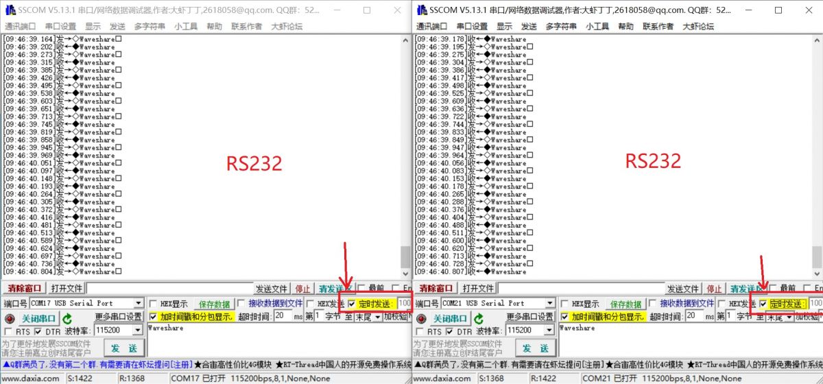
- Open two SSCOM windows and the corresponding COM port numbers.

- Select the baud rate as 115200, input the characters to be sent, check show time and package, and click on Open COM:

- Set the two SSCOM windows sending at 100ms intervals, and then you can see the 2 Windows send and receive data normally, the effect as shown below:
RS485 Test
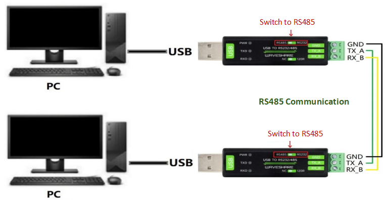
- Connect the RS485 connector of the USB TO RS232/485 module, that is, A+ --> A+, B- --> B-, GND --> GND, and switch the toggle switch on it to RS485, the connection diagram is referenced below:
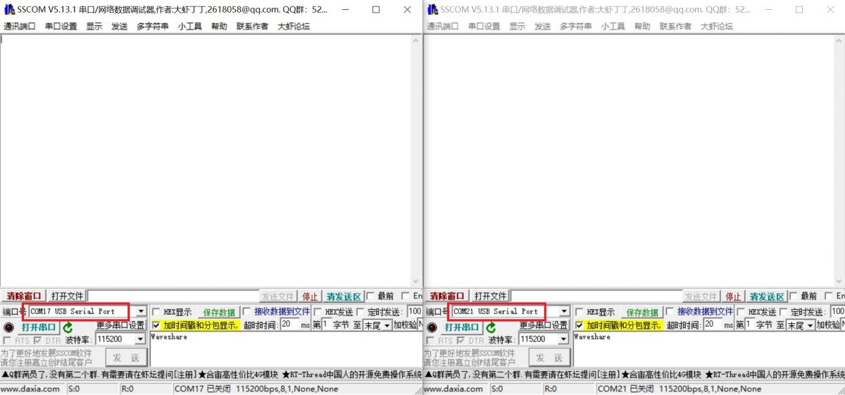
- Open two SSCOM windows on the PC and the corresponding COM ports:
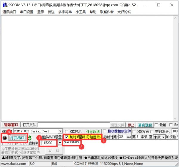
- Select the baud rate as 115200, input the characters to be sent, check show time and package, and Open COM.
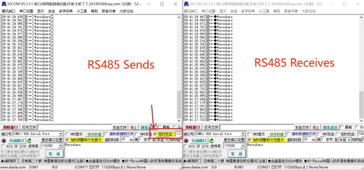
- Select one SSCOM, send it at 100ms intervals, and then you can the 2 Windows send and receive data as shown below:
Resource
Datasheet
Software & Driver
- VCP driver (or you can download it from FTDI website)
- Support Linux driver free.
- SSCOM
Support
Monday-Friday (9:30-6:30) Saturday (9:30-5:30)
Email: services01@spotpear.com
TAG:
Jetson Nano 5G module
Install Espressif IDF Plugin Tutorial User Guide
DPI Interface
Raspberry Pi 1.3inch LCD
ESP32-S3 Development Board 3.16 inch LCD display 3.16inch Screen SD slot 320x820 RGB LED ST7701
Raspberry Pi Pico
X1201 Raspberry Pi 5 UPS Board Uninterruptible Power Supply For 18650-Li-Battery (NOT includ)
Raspberry Pi 5 PCIe to 2.5G Ethernet Adapter Board Plug and Play
MPTPU Raspberry Pi 5 TPU AI Kit 2TOPS PCIe to TPU HAT Pi5 For Google Coral Edge TPU
USB TO TTL Mini FT232 UART Communication Converter Original FT232RNL
ESP32 C3 LCD
Jetson Nano
A7670E LTE Cat-1 HAT for Raspberry Pi Multi Band 2G GSM / GPRS LBS
101M-8001280-IPS-CT-K User Guide
RS485 to Ethernet
Raspberry Pi Camera V1
2.8inch Capacitive TouchScreen LCD Display ST7789 CST328 240x320 For Arduino/Raspberry Pi/ESP32/Pico
0.85inch Screen
Raspberry Pi PICO
Sipeed Lichee Tang Nano 20K FPGA RISCV Open-Source Retro-Game Linux MINI Development Board GW2AR-18