


- sales/support
Google Chat:---
- sales
+86-0755-88291180
- sales01
sales@spotpear.com
- sales02
dragon_manager@163.com
- support
tech-support@spotpear.com
- CEO-Complaints
zhoujie@spotpear.com
- Only Tech-Support
WhatsApp:13246739196
- Purchase/Shipping/Refund
WhatsApp:13424403025
- HOME
- >
- ARTICLES
- >
- Common Moudle
- >
- ESP
ESP32-S3-Touch-LCD-1.83 User Guide
Introduction
Introduction
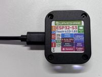
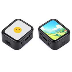
ESP32-S3-Touch-LCD-1.83 is a high-performance and highly integrated MCU board designed by Waveshare. It is equipped with a 1.83inch capacitive LED screen, a highly integrated power management chip, a 6-axis sensor (3-axis accelerometer and 3-axis gyroscope), RTC, low-power audio codec chip and other peripherals in a smaller board size, which are convenient for development and embedding into the product.
Features
- Equipped with ESP32-S3R8 high-performance Xtensa 32-bit LX7 dual-core processor, up to 240MHz main frequency
- Supports 2.4GHz Wi-Fi (802.11 b/g/n) and Bluetooth 5 (BLE), with onboard antenna
- Built-in 512KB SRAM and 384KB ROM, stacked with 8MB PSRAM and external 16MB Flash
- Adopts Type-C interface to improve user convenience and device compatibility
- Onboard 1.83inch capacitive touch screen with 240 × 284 resolution, 65K color
- Embedded with ST7789P driver chip and CST816D capacitive touch control chip, using SPI and I2C communication respectively, minimizes required IO pins
- Onboard QMI8658 6-axis IMU (3-axis accelerometer and 3-axis gyroscope) for detecting motion gesture, step counting, etc.
- Onboard PCF85063 RTC chip connected to the battery via the AXP2101 for uninterrupted power supply
- Onboard programmable PWR and BOOT side buttons for customized function development
- Onboard 3.7V 1.2mm lithium battery recharge/discharge header
- Leads to 1 x I2C, 1 x UART, and 1 x USB pad, which can be used for external devices and debugging, and flexibly configure peripheral functions
- Onboard TF card slot for extended storage and fast data transfer, flexible for data recording and media playback, simplifying circuit design
- AXP2101 provides an efficient power management solution, supporting configurable output voltages, integrating charging and battery management functions, which helps to extend battery life
- High touch screen transmittance, fast response and long lifetime
LED Screen Specifications

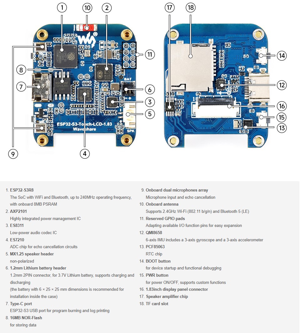
Onboard Resources
- Onboard ESP32-S3R8, supports Wi-Fi and Bluetooth, 240MHz operating frequency, stacked with 8MB PSRAM, as shown in figure ①
- Onboard AXP2101 high integration power management chip, as shown in figure ②
- Onboard ES8311 low-power audio codec chip, as shown in figure ③
- Onboard ES7210 ADC chip implements echo cancellation circuit, as shown in figure ④
- Onboard 1.2mm lithium battery header, as shown in figure ⑥
- Onboard Type-C port for programming and log printing, as shown in figure ⑦
- Onboard 16MB NOR-Flash for data storage, as shown in figure ⑧
- Onboard SMD microphone array for microphone input and echo cancellation, as shown in figure ⑨
- Onboard SMD antenna, supports 2.4GHz Wi-Fi and Bluetooth 5 (LE), as shown in figure ⑩
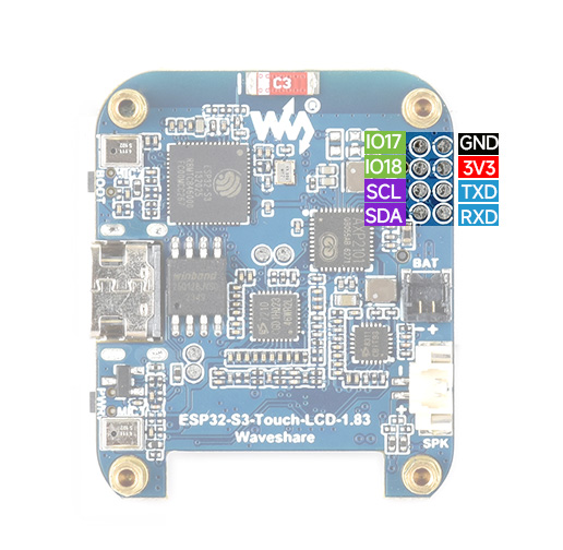
- Onboard reserved GPIO pads, bringing out usable IO function pins for easy expansion, as shown in figure ⑪
- Onboard QMI8658 6-axis IMU containing a 3-axis gyroscope and a 3-axis accelerometer, as shown in ⑫
- Onboard PCF85063 RTC clock chip, as shown in figure ⑬
- Onboard BOOT button for device startup and functional debugging, as shown in figure ⑭
- Onboard PWR power button to control power on and off, support custom functions, as shown in figure ⑮
- Onboard 1.83inch display panel connector, as shown in figure ⑯
- Onboard speaker amplifier chip, as shown in figure ⑰
- Onboard TF card slot, as shown in figure ⑱
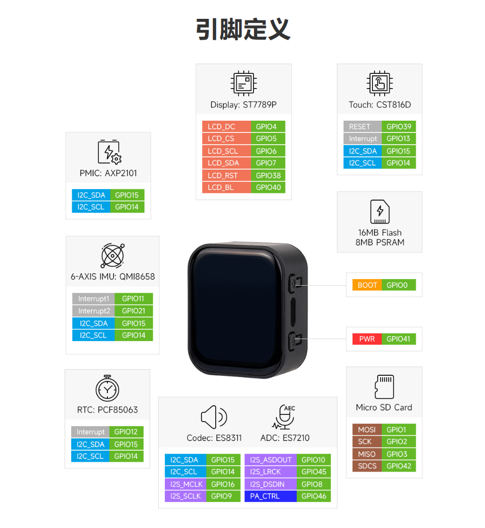
Pinout Definition
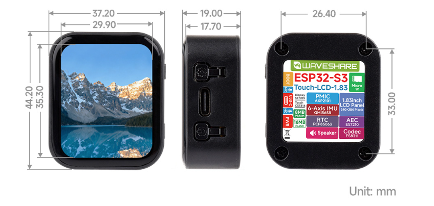
Dimensions
User Guide
ESP32-S3-Touch-LCD-1.83 currently provides two development tools and frameworks, Arduino IDE and ESP-IDF, providing flexible development options, you can choose the right development tool according to your project needs and personal habits.
Development Tool
| Arduino IDEArduino IDE is an open source electronic prototyping platform, convenient and flexible, easy to get started. After a simple learning, you can start to develop quickly. At the same time, Arduino has a large global user community, providing an abundance of open source code, project examples and tutorials, as well as rich library resources, encapsulating complex functions, allowing developers to quickly implement various functions. |
| ESP-IDFESP-IDF, or full name Espressif IDE, is a professional development framework introduced by Espressif Technology for the ESP series chips. It is developed using the C language, including a compiler, debugger, and flashing tool, etc., and can be developed via the command lines or through an integrated development environment (such as Visual Studio Code with the Espressif IDF plugin). The plugin offers features such as code navigation, project management, and debugging, etc. |
Each of these two development approaches has its own advantages, and developers can choose according to their needs and skill levels. Arduino are suitable for beginners and non-professionals because they are easy to learn and quick to get started. ESP-IDF is a better choice for developers with a professional background or high performance requirements, as it provides more advanced development tools and greater control capabilities for the development of complex projects.
Components Preparation
- ESP32-S3-Touch-LCD-1.83 x1
- TF card x 1
- Lithium battery x1
Precautions for Using Lithium Batteries
- Lithium polymer and lithium-ion batteries are very unstable. They may cause fire, personal injury, or property damage, if they're not properly recharged or used.
- When charging and discharging the battery pack, never connect the electrodes incorrectly. Do not use inferior charger/charging panel to recharge the battery.
- Do not mix and use old batteries with new ones, and avoid using batteries from other brands.
- If you need to purchase additional lithium-ion battery products, ensure that the battery parameters are compatible with the lithium-ion battery expansion board. It is recommended to choose batteries from legitimate manufacturers and perform your own aging tests to ensure that the lithium-ion battery can operate stably and safely.
- Lithium batteries have a cycle life, please replace the old batteries with new ones when it reaches the end of its useful life or uses it for two years, whichever comes first.
- Please handle battery products properly, keep them away from flammable and explosive items, and keep them out of reach of children to avoid accidents due to improper storage.
Working with Arduino
This chapter introduces setting up the Arduino environment, including the Arduino IDE, management of ESP32 boards, installation of related libraries, program compilation and downloading, as well as testing demos. It aims to help users master the development board and facilitate secondary development.

Environment Setup
Download and Install Arduino IDE
- Click to visit the Arduino official website, select the corresponding system and system bit to download

- Run the installer and install all by default
Install ESP32 Development Board
- Before using ESP32-related motherboards with the Arduino IDE, you must first install the software package for the esp32 by Espressif Systems development board
- According to board installation requirement, it is generally recommended to use Install Online. If online installation fails, use Install Offline.
- For the installation tutorial, please refer to Arduino board manager tutorial
| Board name | Board installation requirement | Version number requirement |
|---|---|---|
| esp32 by Espressif Systems | "Install Offline" / "Install Online" | ≥3.0.5 |
Install Library
- When installing Arduino libraries, there are usually two ways to choose from: Install online and Install offline. If the library installation requires offline installation, you must use the provided library file
For most libraries, users can easily search and install them through the online library manager of the Arduino software. However, some open-source libraries or custom libraries are not synchronized to the Arduino Library Manager, so they cannot be acquired through online searches. In this case, users can only manually install these libraries offline. - For library installation tutorial, please refer to Arduino library manager tutorial
- ESP32-S3-Touch-LCD-1.83 library file is stored in the sample program, click here to jump: ESP32-S3-Touch-LCD-1.83 Demo
| Library Name | Description | Version | Library Installation Requirement |
|---|---|---|---|
| Arduino_DriveBus | CST816 Touch chip driver library | —— | "Install Offline" |
| GFX_Library_for_Arduino | GFX graphical library for ST7789 | v1.4.9 | "Install Online" or "Install Offline" |
| lvgl | LVGL graphical library | v8.4.0 | "Install Online" requires copying the demos folder to src after installation. "Install Offline" is recommended |
| Mylibrary | Development board pin macro definition | —— | "Install Offline" |
| SensorLib | PCF85063, QMI8658 sensor driver library | v0.2.1 | "Install Online" or "Install Offline" |
| lv_conf.h | LVGL configuration file | —— | "Install Offline" |
Run the First Arduino Demo
New Project
- Run the Arduino IDE and select
File->New Sketch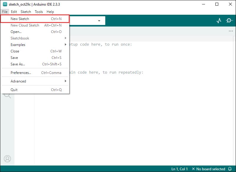
- Enter the code:
void setup() {
  // put your setup code here, to run once:
  Serial.begin(115200);
}

void loop() {
  // put your main code here, to run repeatedly:
  Serial.println("Hello, World!");
  delay(2000);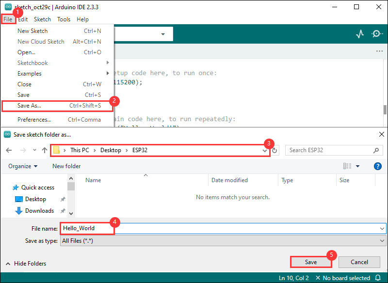
}- Save the project and select
File->Save As.... In the pop-up menu, select the path to save the project, and enter a project name, such as Hello_World, clickSave
Compile and Flash Demos
- Select the corresponding development board, take the ESP32S3 motherboard as an example:
①. Click to select the dropdown menu option Select Other Board and Port;
②. Search for the required development board model esp32s3 dev module and select;
③. Select COM Port;
④. Save the selection.
- If the ESP32S3 mainboard only has a USB port, you need to enable USB CDC, as shown in the following diagram:

- Compile and upload the program:
①. Compile the program; ②. Compile and download the program; ③. Download successful.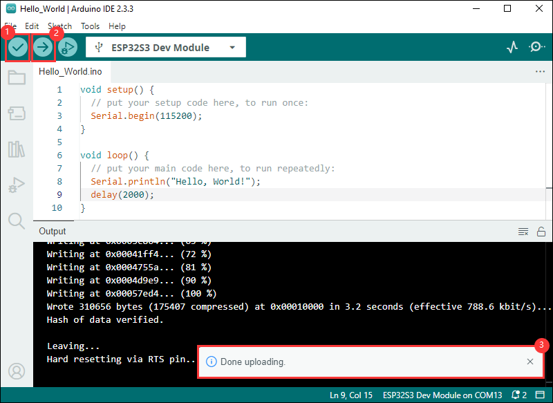
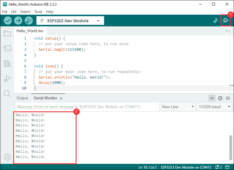
- Open the Serial Monitor window, and the demo will print "Hello World!" every 2 seconds, and the operation is as follows:
Demo

| Demo | Basic Description | Dependency Library |
|---|---|---|
| 01_HelloWorld | Demonstrates the basic graphics library functions and can also be used to test the basic performance of display screens and the display effect of random text | GFX_Library_for_Arduino |
| 02_Drawing_board | Demonstrates the basic graphics library functions and can also be used to test the basic performance of display screens and the display effect of random text | GFX_Library_for_Arduino, Arduino DriveBus |
| 03_GFX_AsciiTable | Prints ASCII characters in rows and columns on the display screen according to the screen size | GFX_Library_for_Arduino |
| 04_GFX_ESPWiFiAnalyzer | Draws the WiFi band signal strength on the ST7789 display | GFX_Library_for_Arduino |
| 05_GFX_Clock | A simple ST7789 clock example, implemented through basic pointer marking and time management | GFX_Library_for_Arduino |
| 06_GFX_PCF85063_simpleTime | Displays the current time | SensorLib, GFX_Library_for_Arduino |
| 07_LVGL_PCF85063_simpleTime | Use the PCF85063 RTC module to display the current time on the ST7789 display under LVGL | LVGL, SensorLib |
| 08_LVGL_QMI8658_ui | Display graphics using LVGL and communicate with the QMI8658 IMU to obtain accelerometer and gyroscope data | LVGL, SensorLib |
| 09_LVGL_Arduino | LVGL demonstration | LVGL, Arduino DriveBus |
- ESP32-S3-Touch-LCD-1.83 model selection
- Take ESP32-S3-Touch-LCD-1.83 as an example

01_HelloWorld
Hardware connection
- Connect the board to the computer using a USB cable
Code analysis
- Initialize the display:
if (!gfx->begin()) {
   USBSerial.println("gfx->begin() failed!");
 }
- Clear the screen and display text:
 gfx->fillScreen(BLACK);
 gfx->setCursor(10, 10);
 gfx->setTextColor(RED);
 gfx->println("Hello World!");
- GIF display:
 gfx->setCursor(random(gfx->width()), random(gfx->height()));
 gfx->setTextColor(random(0xffff), random(0xffff));
 gfx->setTextSize(random(6), random(6), random(2));
 gfx->println("Hello World!");
Result demonstration
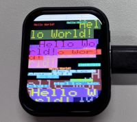
- This example demonstrates how to control the ST7789 display using the Arduino GFX library and the Arduino DriveBus library, demonstrating basic graphics library functionality with dynamically changing text. This code can also be used to test the basic performance of the display and the effect of displaying random text.
02_Drawing_board
Hardware connection
- Connect the board to the computer using a USB cable
Code analysis
- Screen initialization and brightness gradient animation:
 gfx->begin();
 gfx->fillScreen(WHITE);
 for(int i = 0;i <= 255;i++){
   gfx->Display_Brightness(i);
   gfx->setCursor(30, 150);
   gfx->setTextColor(BLUE);
   gfx->setTextSize(4);
   gfx->println("Loading board");
   delay(3);
 }
Result demonstration
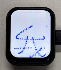
- This example demonstrates how to use the ESP32 to control the CST816 touch controller and TCA9554 GPIO expander via the I2C interface, while using the Arduino GFX library to drive the ST7789 display.
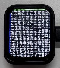
03_GFX_AsciiTable
Hardware connection
- Connect the board to the computer using a USB cable
Code analysis
- Initialize the display:
if (!gfx->begin()) {
   USBSerial.println("gfx->begin() failed!");
 }
- Calculate rows and columns and label them with numbers: Here the number of columns and rows that can be displayed is calculated according to the size of the display. Then use two loops separately, set different text colors, and print the numbers of rows and columns on the display so that the position of the characters can be easily determined when drawing the ASCII characters in the future.
int numCols = LCD_WIDTH / 8;
int numRows = LCD_HEIGHT / 10;

// Label the line number
gfx->setTextColor(GREEN);
for (int x = 0; x < numRows; x++) {
    gfx->setCursor(10 + x * 8, 2);
    gfx->print(x, 16);
}

// Label the column number
gfx->setTextColor(BLUE);
for (int y = 0; y < numCols; y++) {
    gfx->setCursor(2, 12 + y * 10);
    gfx->print(y, 16);
}
- Draw the ASCII character table:
char c = 0;
for (int y = 0; y < numRows; y++) {
    for (int x = 0; x < numCols; x++) {
        gfx->drawChar(10 + x * 8, 12 + y * 10, c++, WHITE, BLACK);
    }
}
Result demonstration
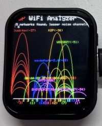
04_GFX_ESPWiFiAnalyzer
Hardware connection
- Connect the board to the computer using a USB cable
Code analysis
setup():
Initialize serial port communication;
Set WiFi to site mode and disconnect;
Initialize the display, obtain the screen size, and calculate various drawing parameters;
Set the screen background to black and draw the title bar.
loop():
Scan WiFi networks and get network information, including channels, RSSI, BSSID, and SSID;
Count the number of networks, noise levels, and peak signal strength on each channel;
Clear old graphics and draw new ones based on the scan results, including signal strength ellipses and network information text;
Print the number of networks scanned and the channel with the least noise;
Draw graph baselines and channel numbering;
Enter the low-power mode according to the conditions.
Result demonstration
- This example demonstrates how to draw a Wi-Fi band signal strength on the ST7789 display, implementing the function of a Wi-Fi analyzer.
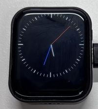
05_GFX_Clock
Hardware connection
- Connect the board to the computer using a USB cable
Code analysis
- Draw hour, minute and second hands:
void redraw_hands_cached_draw_and_erase() {
    gfx->startWrite();
    draw_and_erase_cached_line(center, center, nsx, nsy, SECOND_COLOR, cached_points, sHandLen + 1, false, false);
    draw_and_erase_cached_line(center, center, nhx, nhy, HOUR_COLOR, cached_points + ((sHandLen + 1) * 2), hHandLen + 1, true, false);
    draw_and_erase_cached_line(center, center, nmx, nmy, MINUTE_COLOR, cached_points + ((sHandLen + 1 + hHandLen + 1) * 2), mHandLen + 1, true, true);
    gfx->endWrite();
}
Result demonstration
- This example demonstrates a simple ST7789 clock example, which implements a clock example with a simple marker pointer and time management
06_GFX_PCF85063_simpleTime
Hardware connection
- Connect the board to the computer using a USB cable
Code analysis
loop():- Get the current time first, and if this time is different from the last displayed time, perform the following operations:
- Clear the area for the last displayed time, achieve this by filling a rectangle, so that there won't be overlapping when updating the time display.
- Set the text color to black and the text size to 3.
- Call the getCenteredX function to calculate the X coordinate of the current time string centered on the screen.
- Set the cursor position and print the current time string to update the display of the time.
- Copy the current time string to the previous Timestamp string to determine if the time has changed next time.
Result demonstration
- This example demonstrates how to use the PCF85063 RTC module to display the current time on a ST7789 display, retrieving the time every second and updating the display only when the time changes
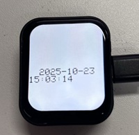
07_LVGL_PCF85063_simpleTime
Hardware connection
- Connect the board to the computer using a USB cable
Code analysis
setup():
Initialize serial communication, prepare possible serial debugging at baud rate of 115200;
Try to connect the PCF85063 real-time clock chip, if the connection fails, enter an infinite loop;
Set the initial time of the real-time clock to October 23, 2025, 15:23:49;
Initialize the display and set the screen brightness;
Initialize LVGL and register the logging output function (if logging is enabled);
Configure the LVGL display driver and drawing buffer, as well as initialize the input device driver (which is a virtual pointer input device driver);
Create a timer to periodically trigger the LVGL clock update
Create a label and set the initial text to "Initializing..."
loop():
Call lv_timer_handler to have LVGL handle graphical interface tasks;
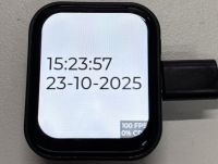
Check the time for updates every second. If it has been updated, obtain the current time of the real-time clock, output it through the serial port, format the time into a specific format, update the text content of the label, and set the label's font to lv_font_montserrat_40.
Result demonstration
- This example demonstrates how to use the PCF85063 RTC module under LVGL to display the current time on a ST7789 display screen, retrieving the time every second and only updating the display when the time changes, which is better than time refresh
08_LVGL_QMI8658_ui
Hardware connection
- Connect the board to the computer using a USB cable
Code analysis
my_disp_flush():
This function is the refresh function of the LVGL display driver. It is responsible for refreshing the LVGL drawing buffer content to the display screen;
Based on different color formats, call the corresponding functions of the gfx object to draw the bitmap to a specific area;
Finally, LVGL is notified that the refresh of the display has been completed.
loop():
Call lv_timer_handler to have LVGL handle graphical interface tasks;
Check if new data is ready for the QMI (QMI8658 sensor object). If available, attempt to acquire acceleration data and gyroscope data, and output through the serial port;
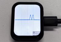
At the same time, the acceleration data is updated to the LVGL graph to show the change of acceleration on the three axes in real time;
Increase the frequency of data polling with delay(20) to ensure that sensor data is captured in a timely manner and the display is updated.
Result demonstration
- This example demonstrates the use of LVGL for graphical display, communicating with the QMI8658 IMU to obtain accelerometer and gyroscope data
09_LVGL_Arduino
Hardware connection
- Connect the board to the computer using a USB cable
Result demonstration
This example demonstrates LVGL Widgets, achieving a frame rate of 20 to 30 frames in dynamic state
Use of LVGL components
When developing using the LVGL framework, you can call the components according to the component instructions provided in the LVGL official documentation: LVGL8.3 Documents
Below is a case study of LVGL actual components in the Arduino IDE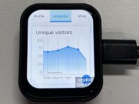
Working with ESP-IDF
This chapter introduces setting up the ESP-IDF environment setup, including the installation of Visual Studio and the Espressif IDF plugin, program compilation, downloading, and testing of demos, to assist users in mastering the development board and facilitating secondary development.

Environment Setup
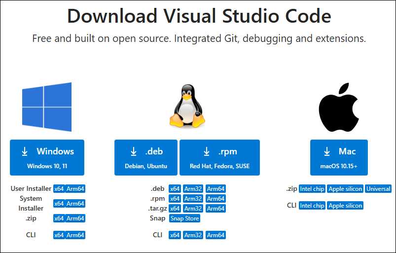
Download and Install Visual Studio
- Open the download page of VScode official website, choose the corresponding system and system bit to download
- After running the installation package, the rest can be installed by default, but here for the subsequent experience, it is recommended to check boxes 1, 2, and 3
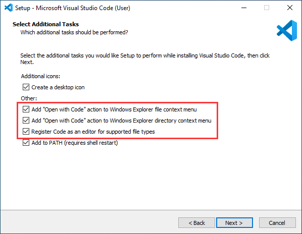
- After the first two items are enabled, you can open VSCode directly by right-clicking files or directories, which can improve the subsequent user experience.
- After the third item is enabled, you can select VSCode directly when you choose how to open it
Install Espressif IDF Plugin
- It is generally recommended to use Install Online. If online installation fails due to network factor, use Install Offline.
- For more information about how to install the Espressif IDF plugin, see Install Espressif IDF Plugin
Run the First ESP-IDF Demo
New Project

Create Demo
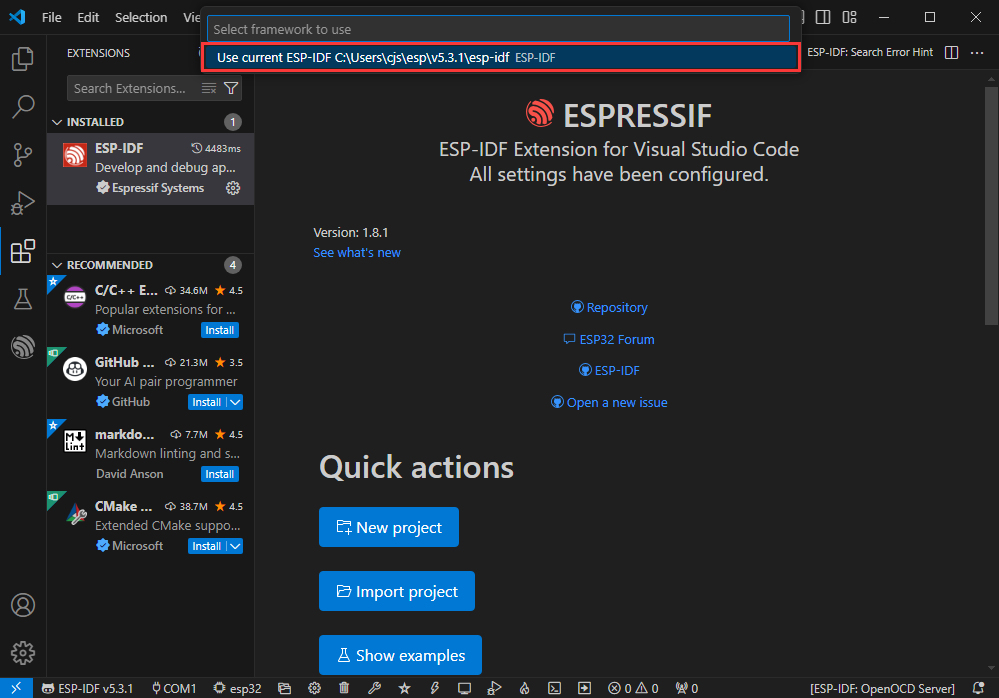
- Using the shortcut F1, enter esp-idf:show examples projects
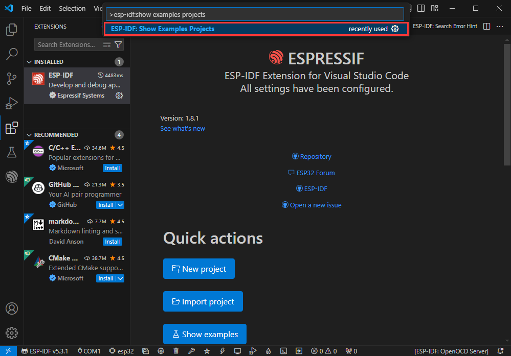
- Select your current IDF version
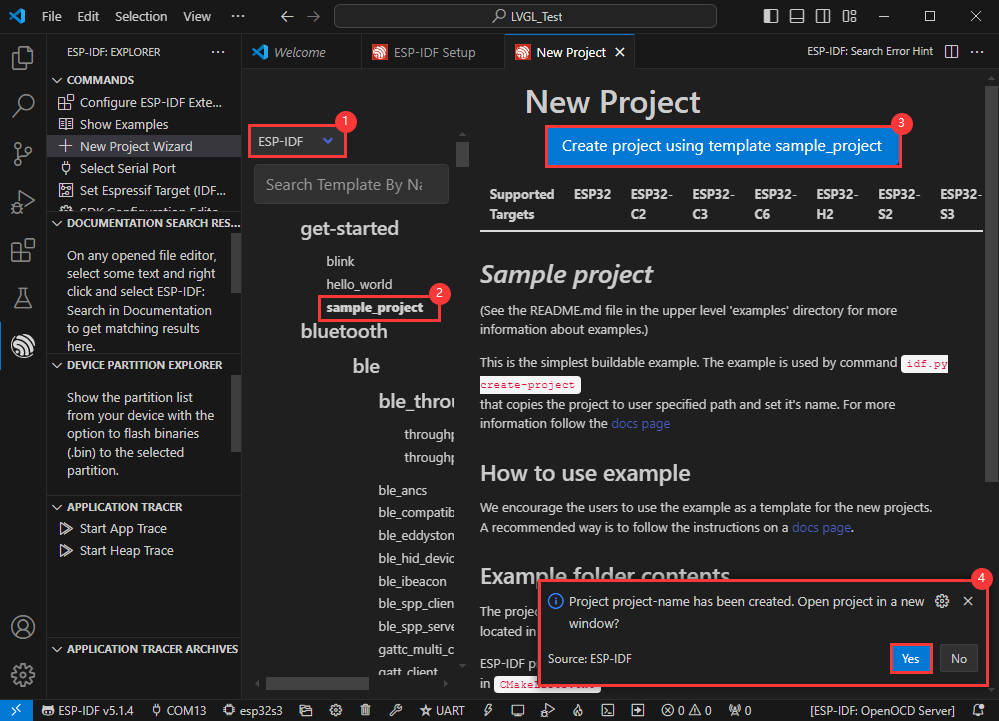
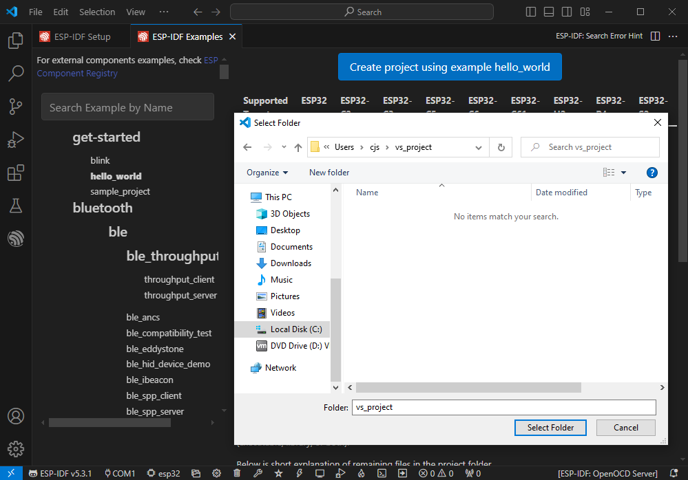
- Take the Hello world demo as an example
①Select the corresponding demo
②Its readme will state what chip the demo applies to (how to use the demo and the file structure are described below, omitted here)
③Click to create the demo
- Select the path to save the demo, and require that the demos cannot use folders with the same name
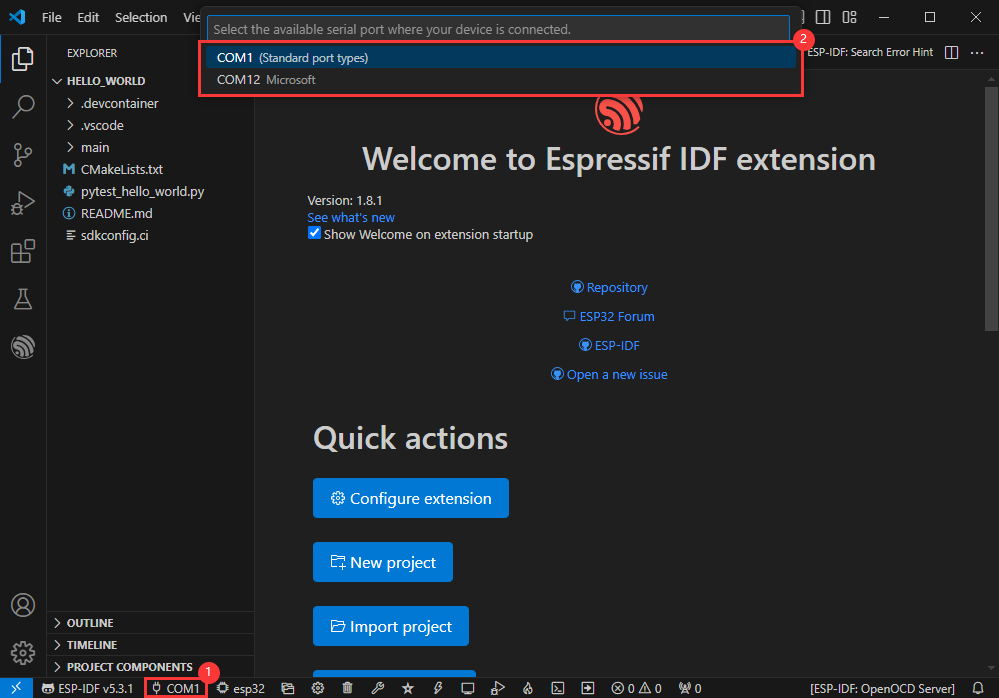
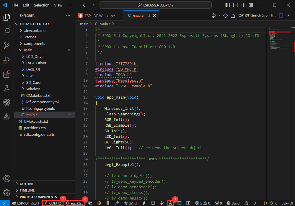
Modify COM Port
- The corresponding COM ports are shown here, click to modify them
- Please select the COM ports according to your device (You can view it from the device manager)
- In case of a download failure, please press the Reset button for more than 1 second or enter download mode, and wait for the PC to recognize the device again before downloading once more
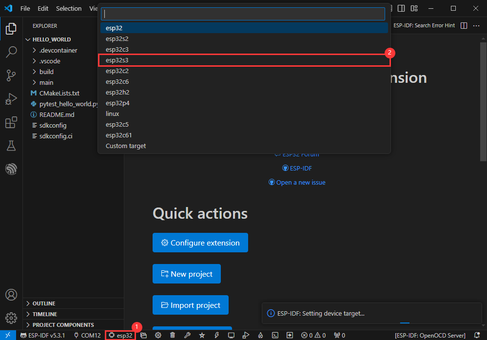
Modify Driver Object
- Select the object we need to drive, which is our main chip ESP32S3
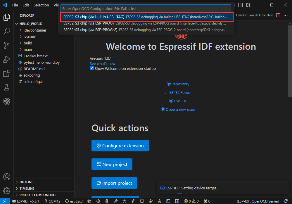
- Choose the openocd path, it doesn't affect us here, so let's just choose one
Other Status Bar Functions
①.ESP-IDF Development Environment Version Manager, when our project requires differentiation of development environment versions, it can be managed by installing different versions of ESP-IDF. When the project uses a specific version, it can be switched to by utilizing it
②.Device flashing COM port, select to flash the compiled program into the chip
③.Select set-target chip model, select the corresponding chip model, for example, ESP32-P4-NANO needs to choose esp32p4 as the target chip
④.menuconfig, click it to modify sdkconfig configuration file, please refer to project configuration details
⑤.fullclean button, when the project compilation error or other operations pollute the compiled content, you can clean up all the compiled content by clicking it
⑥.Build project, when a project satisfies the build, click this button to compile
⑦.Current download mode, the default is UART
⑧.flash button, when a project build is completed, select the COM port of the corresponding development board, and click this button to flash the compiled firmware to the chip
⑨.monitor enable flashing port monitoring, when a project passes through Build --> Flash, click this button to view the log of output from flashing port and debugging port, so as to observe whether the application works normally
⑩.Debug
⑪.Build Flash Monitor one-click button, which is used to continuously execute Build --> Flash --> Monitor, often referred to as "little flame"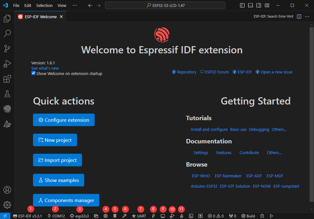
Compile, Flash and Serial Port Monitor
- Click on the all-in-one button we described before to compile, flash and open the serial port monitor
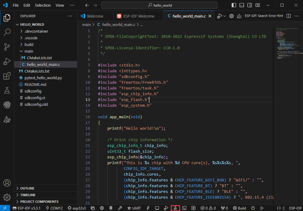
- It may take a long time to compile especially for the first time

- During this process, the ESP-IDF may take up a lot of CPU resources, so it may cause the system to lag
- If it is the first time to flash the program for a new project, you will need to select the download method, and select UART

- This can also be changed later in the Download methods section (click on it to pop up the options)

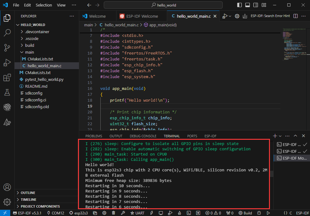
- As it comes with the onboard automatic download circuit, it can be downloaded automatically without manual operation
- After successful download, it will automatically enter the serial monitor, you can see the chip output the corresponding information and be prompted to restart after 10S
Use the IDF Demos
Open In the Software
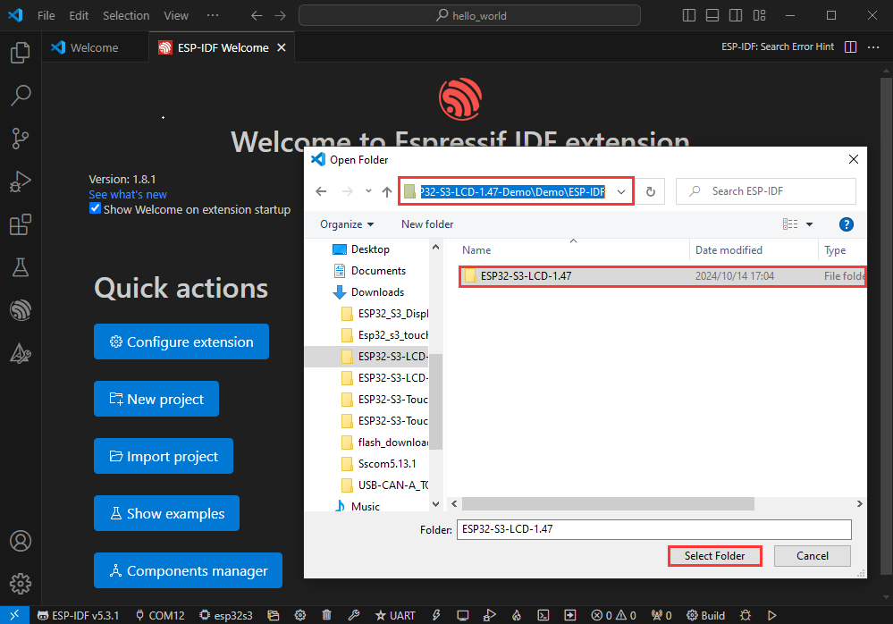
- Open VScode software and select the folder to open the demo
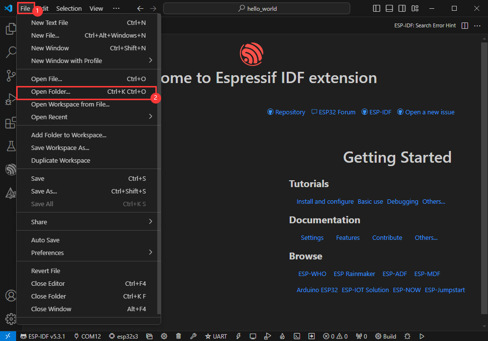
- Select the provided ESP-IDF example and click to select the file (located in the /Demo/ESP-IDF path under demo)
Open from Outside the Software
- Select the project directory correctly and open the project, otherwise it will affect the compilation and flashing of subsequent programs

- After connecting the device, select the COM port and model, click below to compile and flash to achieve program control
ESP-IDF Project Details
- Component: The components in ESP-IDF are the basic modules for building applications, each component is usually a relatively independent code base or library, which can implement specific functions or services, and can be reused by applications or other components, similar to the definition of libraries in Python development.
- Component reference: The import of libraries in the Python development environment only requires to "import library name or path", while ESP-IDF is based on the C language, and the importing of libraries is configured and defined through
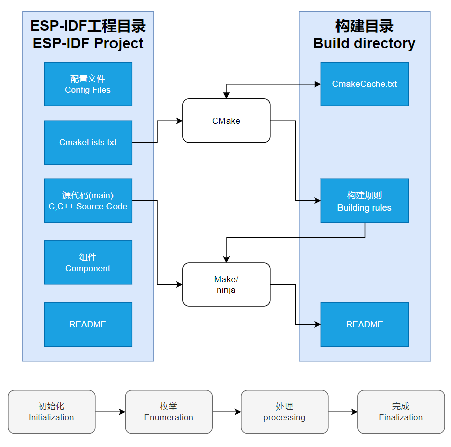
CMakeLists.txt. - The purpose of CmakeLists.txt: When compiling ESP-IDF, the build tool
CMakefirst reads the content of the top-levelCMakeLists.txtin the project directory to read the build rules and identify the content to be compiled. When the required components and demos are imported into theCMakeLists.txt, the compilation toolCMakewill import each content that needs to be compiled according to the index. The compilation process is as follows:
- Component reference: The import of libraries in the Python development environment only requires to "import library name or path", while ESP-IDF is based on the C language, and the importing of libraries is configured and defined through
Demo

| Demo | Basic Description |
|---|---|
| 01_AXP2101 | Obtain power-related data through the ported XPowersLib to drive AXP2101 |
| 02_lvgl_demo_v9 | Run LVGL V9 demo |
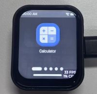
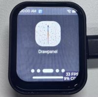
| 03_esp-brookesia | Run esp-brookesia demo, based on the V0.4.2 release version |
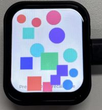
| 04_Immersive_block | Immersive experience of block shaped objects tilting in the direction of gravity using QMI8658 |
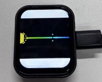
| 05_Spec_Analyzer | Implement a simple audio capture analyzer with LVGL |
| 06_videoplayer | Use LVGL to read AVI video playback from TF card, including audio playback |
01_AXP2101
Demo description
- This demo demonstrates using ESP-IDF to port XPowersLib, and driving AXP2101 to obtain power-related data through the ported XPowersLib
Hardware connection
- Connect the development board to the computer
Code analysis
- i2c_init: Initializes the I2C master in preparation for communication with other devices, such as the PMU
- Configure I2C parameters, including setting the master device mode, specifying the SDA and SCL pins, enabling the pull-up resistor, and determining the clock frequency
- Install the I2C driver and apply the configuration to the actual hardware
- pmu_register_read: Reads a series of bytes of data from a specific register of the PMU
- Perform parameter checks to ensure the incoming parameters are valid and avoid invalid read operations
- Perform I2C operations in two steps, first send the register address to read, then read the data. During the reading process, different processing is carried out according to the length of bytes to be read to ensure accurate reading of the data. At the same time, handle error cases in the I2C communication process and return the corresponding status code so that the upper-layer code can determine if the read operation is successful
Result demonstration
- This demo will not light up the screen
- The serial port monitor displays the parameters: chip temperature, charging state, discharging state, standby state, Vbus connected, Vbus condition, charger status, battery voltage, Vbus voltage, system voltage, battery percentage

02_lvgl_demo_v9
Demo description
- This example runs the LVGL V9 demo
Hardware connection
- Connect the development board to the computer
Result demonstration
03_esp-brookesia
Demo description
- This demo demonstrates the UI interface running with the esp-brookesia framework
Hardware connection
- Connect the development board to the computer
Result demonstration
04_Immersive_block
Demo description
- This demo demonstrates the QMI8658 driving effect, achieving multiple blocks immersive tilting with gravity
Hardware connection
- Connect the development board to the computer
Result demonstration

05_Spec_Analyzer
Demo description
- This demo implements the microphone audio capture function, using FFT to analyze the audio and display it on the screen
Hardware connection
- Connect the development board to the computer
Result demonstration
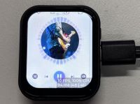
06_videoplayer
Demo description
- This demo demonstrates playing an AVI video file from a TF card, which can also play audio
Hardware connection
- Connect the development board to the computer
Result demonstration


Custom audio
Users can customize audio playback segments by following the steps below (some programming knowledge is required)
- Select the video you want to play (e.g. a.mp4)
- Install ffmpeg tool
- Convert video files to avi format using ffmpeg
ffmpeg -i a.mp4 -vcodec mjpeg -s 'resolution width'x'resolution height' -r 30 -q:v 2 -acodec pcm_s16le -ar 44100 -ac 2 a.avi
- Put the converted avi format file into the /avi/ directory in the TF card
- Insert the TF card into the development board
- Compile and flash
Flash Firmware Flashing and Erasing
- The current demo provides test firmware, which can be used to test whether the onboard device functions properly by directly flashing the test firmware
- bin file path:
..\ESP32-S3-Touch-LCD-1.83-Demo\Firmware
Resources
Schematic Diagram
Demo
Datasheets
ESP32-S3
Other Components
- QMI8658 Datasheet
- PCF85063 Datasheet
- AXP2101 Datasheet
- ES8311 Datasheet
- ES8311 User Guide
- FT3168 Datasheet
- ES7210 Datasheet
Software
- Zimo221 Chinese character conversion software
- Image2Lcd image bitmap conversion software
- Flash_download_tool
Other Resource Links
- Image bitmap conversion tutorial
- Font library conversion tutorial
- MicroPython official documentation
- ESP32 Arduino Core's documentation
- arduino-esp32
- ESP-IDF
FAQ
Question: What is the GPIO corresponding to the reserved GPIO pads on the ESP32-S3-Touch-LCD-1.83 development board?
Question: How to check the COM port you are using?
Windows system:
①Check via Device Manager: Press the Windows + R keys to open the "Run" dialog box; Enter devmgmt.msc and press Enter to open Device Manager; Expand the "Ports (COM & LPT)" section, where all COM ports and their current status will be listed.
②Use Command Prompt to check: Open the Command Prompt (CMD); Enter the mode command, which will display the status information for all COM ports.
③Check hardware connections: If you have already connected an external device to the COM port, it usually occupies a port number, and you can determine which port is being used by checking the connected hardware.
Linux system:
①Use the dmesg command to check: Open the terminal.
②Use the ls command to check: Enter ls /dev/ttyS* or ls /dev/ttyUSB* to list all serial port devices.
③Use the setserial command to check: Enter setserial -g /dev/ttyS* to view the configuration information for all serial port devices.
Question: How to use SquareLine Studio to design interfaces?
- Please refer to SquareLine Studio tutorial
Support
Monday-Friday (9:30-6:30) Saturday (9:30-5:30)
Email: services01@spotpear.com
[Tutorial Navigation]
- Introduction
- User Guide
- Working with Arduino
- Working with ESP-IDF
- Environment Setup
- Run the First ESP-IDF Demo
- New Project
- Create Demo
- Modify COM Port
- Modify Driver Object
- Other Status Bar Functions
- Compile, Flash and Serial Port Monitor
- Use the IDF Demos
- Demo
- Flash Firmware Flashing and Erasing
- Resources
- FAQ
- Question: What is the GPIO corresponding to the reserved GPIO pads on the ESP32-S3-Touch-LCD-1.83 development board?
- Question: How to check the COM port you are using?
- Question: How to use SquareLine Studio to design interfaces?
- Support