- sales/support
Google Chat:---
- sales
+86-0755-88291180
- sales01
sales@spotpear.com
- sales02
dragon_manager@163.com
- support
tech-support@spotpear.com
- CEO-Complaints
zhoujie@spotpear.com
- sales/support
WhatsApp:13246739196
- HOME
- >
- ARTICLES
- >
- Common Moudle
- >
- Sensors
Motor Driver Board User Guide
Introduction
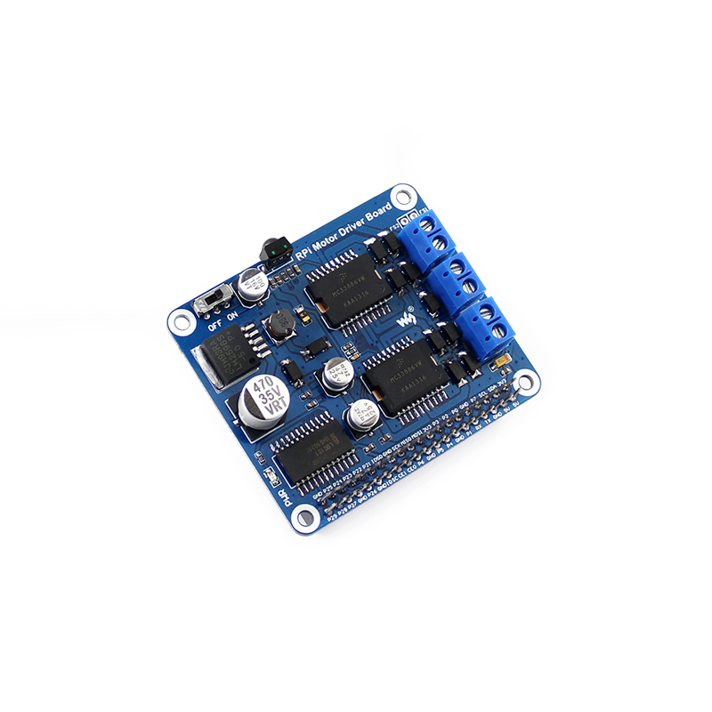
Raspberry Pi Expansion Board, DC Motor / Stepper Motor Driver
Interface definitions
| Interface | wiringPi | BCM |
|---|---|---|
| M1 | P28 | 20 |
| M2 | P29 | 21 |
| PWMA | P25 | 26 |
| M3 | P22 | 6 |
| M4 | P23 | 13 |
| PWMB | P26 | 12 |
M1 and M2 are connected to the right motor, while M3 and M4 are connected to the left motor. PWMA and PWMB are output enable pins, active high enable. When they are driven to High level, the PWM pulse will be outputted from M1, M2, M3 and M4, so as to control the speed of the robot.
Control work
| M1 | M2 | M3 | M4 | Descriptions |
|---|---|---|---|---|
| 1 | 0 | 1 | 0 | When the motors rotate forwards, the robot goes straight |
| 0 | 1 | 0 | 1 | When the motors rotate backwards, the robot draws back |
| 0 | 0 | 1 | 0 | When the right motor stops and left motor rotates forwards, the robot turns right |
| 1 | 0 | 0 | 0 | When the left motor stops and right motor rotates forwards, the robot turns left |
| 0 | 0 | 0 | 0 | When the motors stop, the robot stops |
Examples
There are two examples for this module, one is for infrared remote control, and the other is for website remote control with real-time monitor via a Raspberry Pi camera. (Notes: The chassis and the camera are not provided with the module, and have to be purchased separately.)
The examples demonstrated in the section below are available from here. To follow along with the examples, you just need to extract the relative file's contents into a folder under the directory of /home/pi in the Raspbian system. (Of course, you should copy them into the Raspberry Pi via your U disk first.)
Infrared remote control
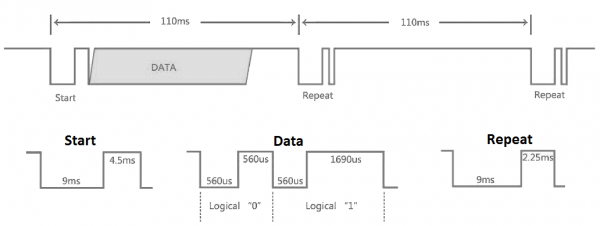
This test demonstrates how to remote control the robot with an infrared remote controller. The pulse signal from the infrared remote controller complies with the NEC standard. The infrared remote receiver outputs the pulse to the Pin 18 of the BCM after relative signal received. Then, the Raspberry Pi reads the pulse from the Pin 18 and decodes it, so as to control the corresponding motor. For more detailed information, please refer to the source code of the example
Infrared NEC protocol coding description
Data format: Address, ~(Address), Command, ~(Command)
~(Address): bit-wise complement of Address. ~(Command): bit-wise complement of Command
Both address and command are in a format of 8 bits, so a complete signal is in 32 bits.
This example is based on the Python library, which has been in the latest Raspbian system. However, if there is any error occurs when running the example, you should install the Python library manually. In case that the example is unable to be performed after installing the library, you can try to apply the command chmod +x filename to grant the program the executable permission.
Enter the Linux terminal, and input the following command
cd ~/RPi-Motor-Driver-Board-Demo-Code/python
sudo python motor.py
Expected result: Pressing the keyboard of the infrared remote controller can control the robot. The key 2 is for go straight, 8 for drawback, 4 for turn left, 6 for turn right, and 5 for stop. The keys – and + are speed control keys. (Notes: Since the keyboard coding varies from different infrared remote controllers, you may need to modify the program as required.)
Website remote control
This test demonstrates how to remote control the robot via webiopi, and real-time display the image captured by the camera with the software mjpg-streamer. For some browser may be unable to display the image correctly, we recommend you to use the Chrome browser or the Firefox browser.
Step 1. Install webiopi
cd ~/RPi-Motor-Driver-Board-Demo-Code/WebIOPi-0.7.1-raspi2
sudo ./setup.sh
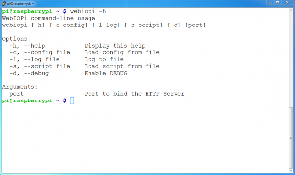
Check the installation: run the command webiopi –h. When the library is installed successfully, you can see the following information as the figure shown below.
Enter the terminal, and input the line below:
sudo webiopi -d -c /etc/webiopi/config
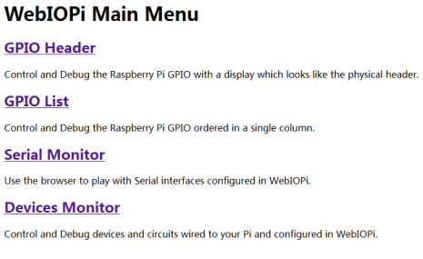
Then, open the browser on your PC or cell phone, and enter the IP address of RPi and the port number: 8000 into the address bar. For example, input http://192.168.1.16:8000 (the address can be changeable according to your actual condition). To login the website, you should enter your account and password. The default account name is webiopi, and the original password is raspberry. When finished the steps above, if you can enter the webpage WebIOPi Main Menu, it means the environment is configured well.
Under the terminal, press the keys Ctrl + C to end the program.
Step 2. Install and use mjpg-streamer
This section describes the new function: camera, since the RPi can be connected with a camera. If you application do not need this function, please jump to the next section.
a) Run the command raspi-config to start up the camera before using it:
sudo raspi-config
Then, select the option Enable Camera.
b) For the camera with CSI interface, the system may be unable to find out the device under the directory of /dev/video0. In this case, you should add a line, bcm2835-v4l2, into the file /etc/modules.
sudo nano /etc/modules
Add the line:
- bcm2835-v4l2
c) After reboot, the system will load the module name stored in this file, and find out the device video0 under the directory of /dev. (Please take a notice that the letter l in the command bcm2835-v4l2 is the lower case of L.)
d) Install dependent libraries:
sudo apt-get install libv4l-dev libjpeg8-dev
sudo apt-get install subversion
e) Compile the example:
cd ~/RPi-Motor-Driver-Board-Demo-Code/mjpg-streamer/
make USE_LIBV4L2=true clear all
During the make command running, you may see a warning: make: *** No rule to make target 'clear'. Stop. This warning can be ignored.
f) If there is any error occurred, you can try to modify the content of the file mjpg-streamer/plugins/input_uvc/input_uvc.c, changing V4L2_PIX_FMT_MJPEG to V4L2_PIX_FMT_YUYV
g) Start up mjpg-streamer:
sudo ./start.sh
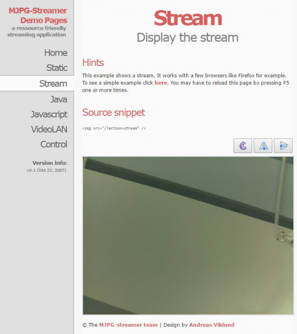
Then, open the browser, and enter the IP address of RPi and the port number: 8080 into the address bar. (Notices: the port number here is 8080, other than 8000 what we used before.) The website will show the information about the M-JPEG streamer. Click the option Stream, it will real-time display the image captured by the camera.
Under the terminal, pressing the keys Ctrl + C can end the program. However, it should be kept running, since we still need it in the following operations.
Step 3. Run the robot program
Open another terminal; don’t end the program in the step 2.
Enter the directory of magpi-cambot, which contains the source code for controlling the robot.
cd ~/RPi-Motor-Driver-Board-Demo-Code/magpi-cambot
Modify the file index.html:
sudo nano index.html
You should modify the html tag according to the IP of Raspberry Pi in used.
<img width="320" height="240" src="http://192.168.1.16:8080/?action=stream">
In here, “src” is followed by the IP address of RPi: 192.168.1.16 and the port number: 8080 (This port is used for transmitting stream).
Start up the cambot program:
cd ~/RPi-Motor-Driver-Board-Demo-Code/magpi-cambot
sudo webiopi -d -c /etc/webiopi/config
Then, open the browser, and enter the IP address of RPi and the port number: 8000 into the address bar. (Notices: the port number here is 8000, other than 8080.)
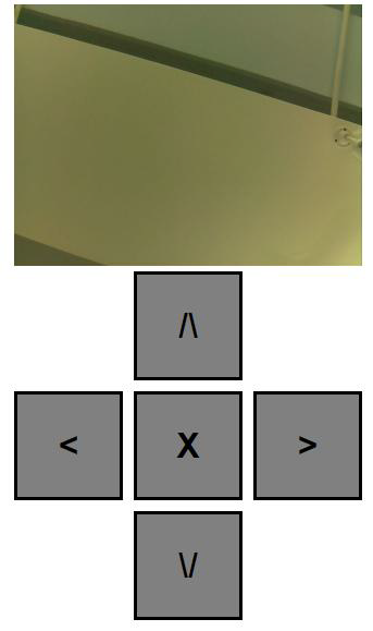
The image captured by the camera will be shown in the website. Clicking the direction icon on the website can control the action of the robot.
If you cannot enter this webpage, we recommend you to use the Chrome browser or the Firefox browser. Furthermore, please make sure the current directory of Raspberry Pi is ~/RPi-Motor-Driver-Board-Demo-Code/Webiopi and there should be a file index.html under this directory. And then, input the code
sudo webiopi -d -c /etc/webiopi/config
to enter the index.html. Or else, you will go to the WebIOPi Main Menu webpage.


