- sales/support
Google Chat:---
- sales
+86-0755-88291180
- sales01
sales@spotpear.com
- sales02
dragon_manager@163.com
- support
tech-support@spotpear.com
- CEO-Complaints
zhoujie@spotpear.com
- sales/support
WhatsApp:13246739196
- HOME
- >
- PRODUCTS
- >
- Other Board
- >
- STM32
- >
- Downloader
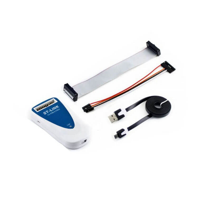
ST LINK, STM Programmers & Debuggers
$29.89
In-Circuit Debugger And Programmer For STM8 And STM32 MCUs; With IAR EWARM And Keil RVMDK And ST Toolset
Description
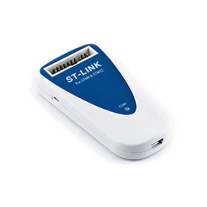
The ST-LINK is an in-circuit debugger and programmer for the STM8 and STM32 microcontroller families. The SWIM and JTAG/SWD interface is used to communicate with the STM8 or STM32 microcontroller located on your own application board.
On the PC side, the USB full speed interface is used to communicate with:
- ST Visual Develop (STVD) or ST Visual Program (STVP) software from
STMicroelectronic's for the STM8, - ATOLLIC, IAR and KEIL Integrated Development Environments for the STM32.
Key Features
- 5 V power supplied by USB connector
- USB 2.0 full speed interface compatible
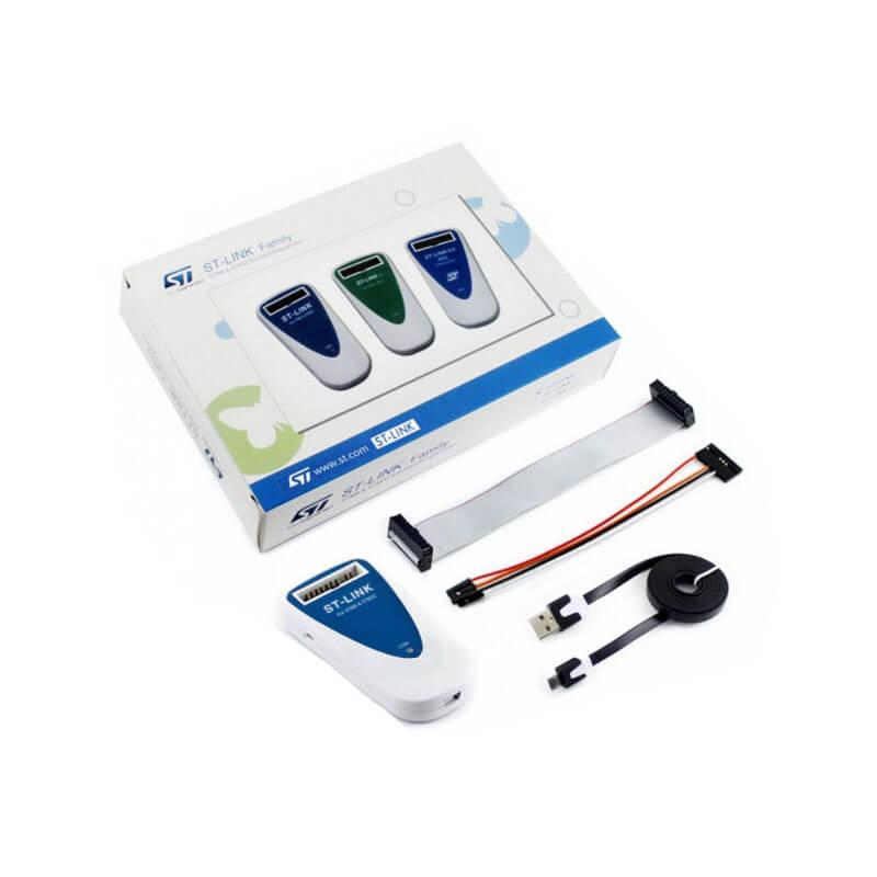
- USB standard A to micro cable provided
- SWIM specific features:
- 1.65 V to 5.5 V application voltage supported on SWIM interface
- SWIM low speed and high speed modes supported
- SWIM programming speed rate:
- 9.7 Kbytes/s in low speed
- 12.8 Kbytes/s in high speed
- SWIM cable for connection to an application with pin headers or 2.54 mm pitch connector
- JTAG/SWD specific features:
- 3 V to 3.6 V application voltage supported on JTAG/SWD interface and 5 V tolerant inputs
- JTAG/SWD cable provided for connection to a standard JTAG 20-pin pitch 2.54 mm connector
- Direct firmware update feature supported
- Status LED which blinks during communication with PC
- Operating temperature 0 to 50 °C
Release History
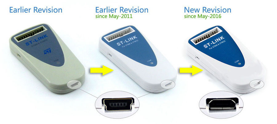
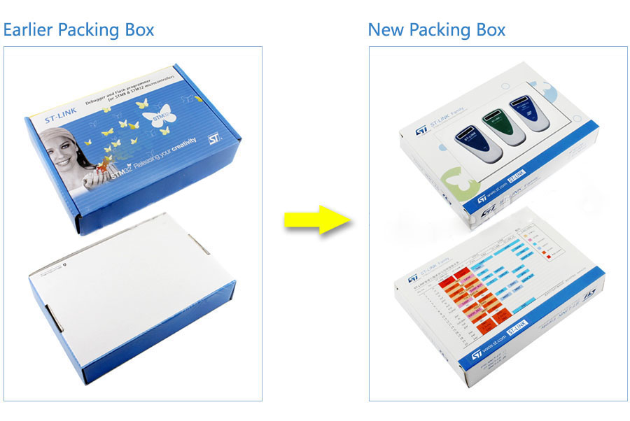
Since May-2016, ST-LINK New Revision has been released. Now it employs a micro USB connector.
Application Example
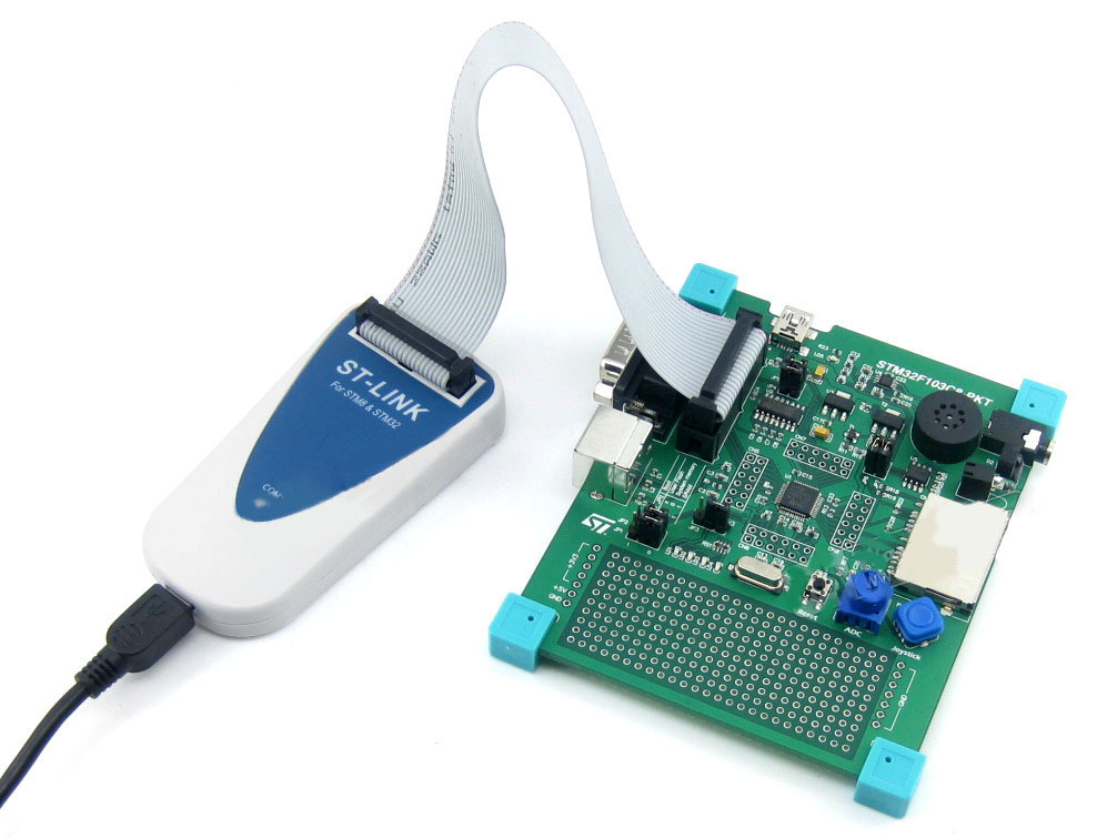
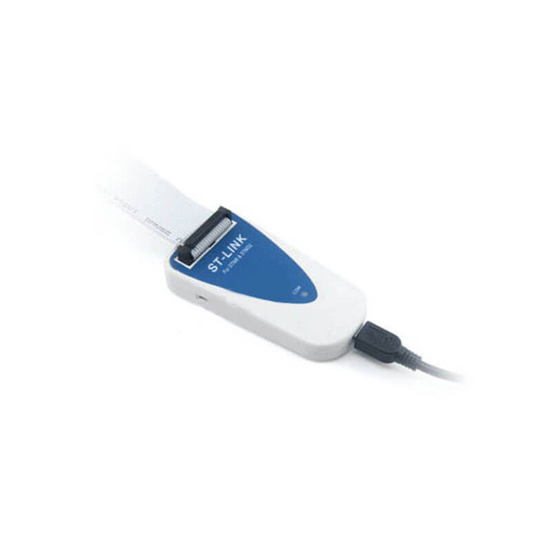
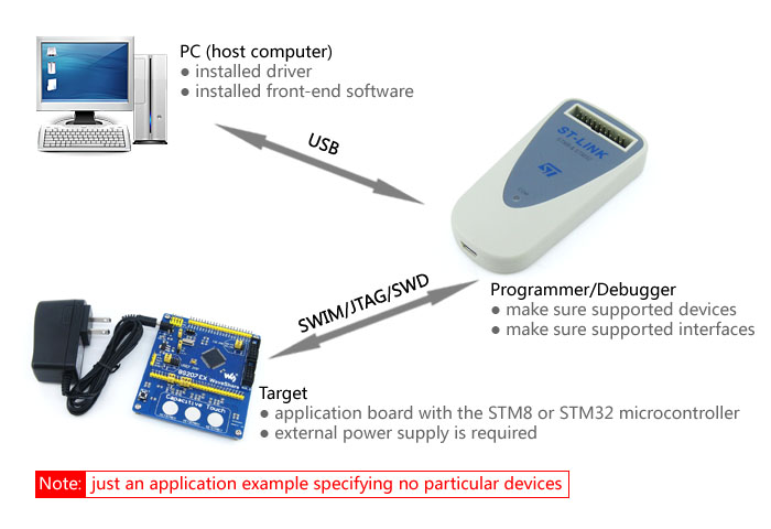
Connecting the PC and STM8/STM32 application board through a ST-LINK to establish hardware connection:
Supported Devices
Microcontrollers supported by STVP release 3.2.8:
| PRODUCT LINE | MICROCONTROLLER |
|---|---|
| STM32 | STM32F100xx, STM32F101xx, STM32F102xx, STM32F103xx, STM32F105xx, STM32F107xx, STM32F2xxx, STM32F4xxx, STM32L15xx6, STM32L15xx8,STM32L15xxB, STM32L151xC, STM32L151xD, STM32L152xC, STM32L152xD, STM32L162xD, STM32TS60, STM32W108C8, STM32W108xB, STM32W108xC, STM32W108xZ |
| STM8 | STM8AF51x, STM8AF52x, STM8AF61x, STM8AF62x,STM8AH51x, STM8AH61x, STM8S003K3, STM8S003F3, STM8S005C6, STM8S005K6, STM8S007C8, STM8S103xx, STM8S105xx, STM8S207xx, STM8S208xx, STM8S903F3, STM8S903K3, STM8L101xx, STM8L15x, STM8L16x, STM8TL52x4,STM8TL53x4 |
Connection with STM8 applications
The ST-LINK should be connected to the STM8 application via the SWIM separate-wires cable, which is delivered with the product.
As the SWIM separate-wires cable has independent connectors for all pins on one side, it is possible to connect the ST-LINK to an application board without a standard SWIM connector. On this flat ribbon all signals are referenced by a specific color and a label to ease the connection on target.
Figure 1. Standard SWIM header pinout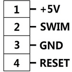
Figure 2. SWIM separate-wires cable connected on ST-LINK target connector even pins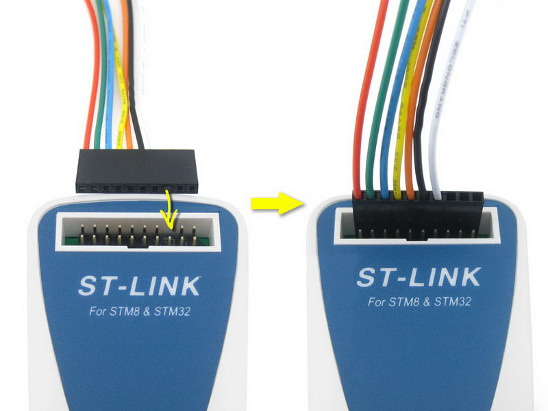
Figure 3. Connected to a STM8 application board via SWIM separate-wires cable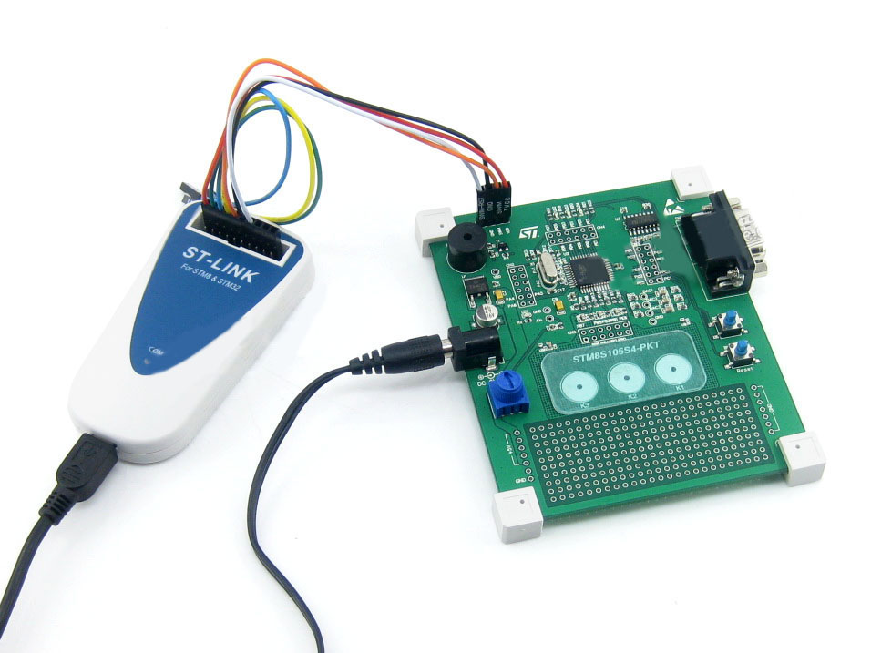
Connection with STM32 applications
For STM32 developments the ST-LINK must be connected to the application using the standard 20-pin female-female JTAG flat ribbon provided.
Figure 4. Debugging connector layout on ST-LINK and flat cable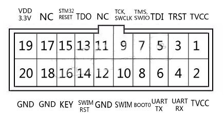
Figure 5. Connected to a STM32 application board
via 20-pin female-female JTAG flat ribbon