- sales/support
Google Chat:---
- sales
+86-0755-88291180
- sales01
sales@spotpear.com
- sales02
dragon_manager@163.com
- support
tech-support@spotpear.com
- CEO-Complaints
zhoujie@spotpear.com
- Only Tech-Support
WhatsApp:13246739196
- Purchase/Shipping/Refund
WhatsApp:13424403025
- HOME
- >
- ARTICLES
- >
- Raspberry Pi
- >
- Raspberry Pi LCD
- >
- e-Paper
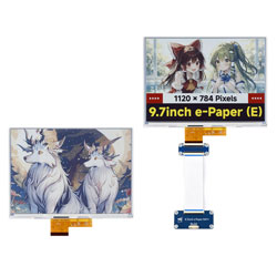
9.7inch e-Paper (E) User Guide
Features
- Uses E Ink Spectra 6 (E6) technology, requires no backlight, and can retain the last displayed content for a long time after power-off
- Very low power consumption, mainly only consumes power during refresh
- Provides comprehensive supporting documentation: driver board schematic, Raspberry Pi / Jetson Nano / Arduino / STM32 / ESP32 example programs, etc.
- The following applies only to the module version (with driver board)
- Designed based on the Raspberry Pi 40PIN GPIO interface, suitable for Raspberry Pi, Jetson Nano
- Reserved SPI communication interface for easy connection to master controllers such as Raspberry Pi / Arduino / STM32 / ESP32
- Onboard level shifter chip, compatible with 3.3V and 5V logic levels
Specifications
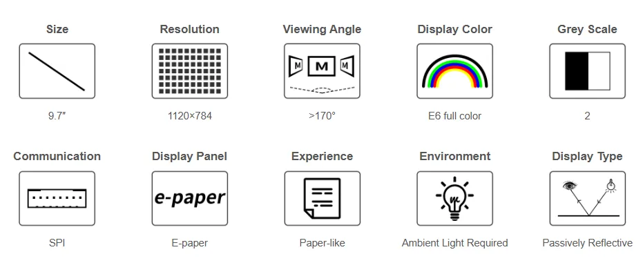
| Parameter | Value |
|---|---|
| Operating Voltage | Raw display: 3.3V with Driver HAT: 3.3V/5V |
| Communication Interface | 3-wire SPI, 4-wire SPI |
| Overall Dimensions | Raw display: 210.8 × 154.9 × 0.74 mm e-Paper driver HAT: 65.00 × 30.50 mm |
| Display Size | 201.60 × 141.12 mm |
| Dot Pitch | 0.18 × 0.18 mm |
| Resolution | 1120 × 784 pixels |
| Display Color | E6 full color (E Ink Spectra 6) |
| Grayscale | 2 |
| Full Refresh Time | 30s |
| Refresh Power Consumption | <0.6W |
| Sleep Current | < 0.01uA (close to 0) |
| Viewing Angle | > 170° |
| Operating Temperature | 0 to 50 ℃ |
| Storage Temperature | -25 to 60 ℃ |
- Refresh Time: The refresh time is based on experimental test data. The actual refresh time may vary; please refer to the actual performance. Flickering during the full refresh process is normal.
- Refresh Power Consumption: Power consumption data is based on experimental test data. Actual power consumption may vary due to the presence of the driver board and different usage conditions; please refer to the actual performance.
- Refreshing at low temperatures may cause color shift. It is recommended to let the screen stand at 25°C for 6 hours before refreshing.
Communication Interface
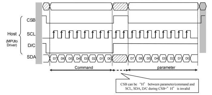
- CSB (CS): Slave chip select signal, active low. The chip is enabled when this signal is low.
- SCL (SCK/SCLK): Serial clock signal.
- D/C (DC): Data/Command control signal. A low level indicates a command is being written; a high level indicates data/parameters are being written.
- SDA (DIN): Serial data signal.
- Timing: CPHA=0, CPOL=0, i.e., SPI mode 0.
- Note: For specific information regarding SPI communication, you can search online for more details.
Working Principle
The e-Paper used in this product employs "Microencapsulated Electrophoretic Display" technology for image display. The basic principle involves charged nanoparticles suspended in a liquid migrating under the influence of an electric field. The e-Paper display relies on reflecting ambient light to show patterns and does not require a backlight. Under ambient light, the e-Paper display is clearly visible, with a viewing angle approaching 180°. Therefore, e-Paper displays are ideal for reading.
Programming Principle
- For black and white images, we can define black as 0 and white as 1. Thus, we have a way to represent colors:
- White: □, corresponds to 1
- Black: ■: corresponds to 0
- A point on an image is generally called a pixel. Since the color is either 1 or 0, 1 bit can represent a pixel: 1 Pixel = 1 bit. Therefore, one byte contains 8 pixels.
- Take 16 pixels as an example. Suppose the first 8 pixels are black and the last 8 pixels are white. We can consider pixels 1-16 correspond to bits 0 to 15, where 0 represents black and 1 represents white:For computers, data storage is typically Most Significant Bit (MSB) first, and one byte consists of only 8 bits. So, there is a slight adjustment:
 In this way, only 2 bytes are required to represent 16 pixels.
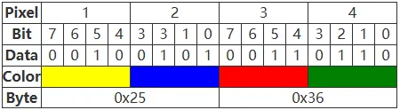
- Now suppose we have six colors, so at least three bits are needed to represent all colors. However, for ease of computation, we add a 0 in front, i.e., use four bits to represent the color of one pixel, so one byte (1 Byte) can represent two pixels. In fact, the controller of this module uses this method.
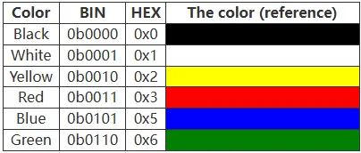
- Taking four pixels as an example, assume the colors of these four points are yellow, blue, red, and green in order. According to the table above, human logic would store them sequentially as:
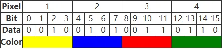
- For a computer, data is stored with the most significant bit first and the least significant bit last, and one byte has only eight bits, so it is stored in bytes as:
Precautions
- Avoid powering the screen for extended periods. When the screen is not refreshing, set it to sleep mode or power it off. Otherwise, prolonged exposure to high voltage can damage the film and is irreparable.
- When using the e-Paper, it is recommended to set a refresh interval of at least 180 seconds and perform a refresh at least once every 24 hours. If the e-Paper will not be used for a long time, store it with a white image displayed. (Refer to the datasheet for specific storage environment requirements.)
- The FPC cable of the screen is delicate. Please note: Do not bend the cable perpendicular to the screen to avoid tearing; do not repeatedly bend the cable excessively to avoid breakage; do not bend the cable towards the front of the screen to avoid disconnecting the cable from the panel. It is recommended to secure the cable during development and debugging.
- The e-Paper screen is relatively fragile. Avoid dropping, impact, or pressing forcefully.
- After the screen enters sleep mode, any image data sent will be ignored. Only re-initialization can restore normal refresh functionality.
- If the generated image data displays incorrectly on the screen, check if the image size settings are correct. Try swapping the width and height settings and test again.
- The operating voltage required for the e-Paper is 3.3V. If you purchased the raw screen and need to integrate it into a 5V environment when designing the circuit, it is recommended to implement level shifting.
We recommend that customers test the screen using the example programs we provide with the corresponding development board upon receiving it.
Image Processing
- Image preparation and conversion for multi‑color e-Paper
Image Preparation
Preparation
- Required software: Adobe PhotoShop CC, Paint
Introduction
- The Floyd‑Steinberg dithering algorithm is very suitable for displaying rich gradation when only a few colors are available. This allows for more color combinations and better shadow rendering of the original image. It is especially suitable for various use scenarios of e-Paper screens.
- The following describes how to convert a normal image into a Floyd‑Steinberg dithered image.
- If you are interested in the actual algorithm, you can look at our porting for ESP32 and ESP8266. Here, no further elaboration will be given.
Operation steps
- Preparation: Download Color table to your PC, and extract it to get the following file, we need to use
N-color.actor4-color.act,6-color.act.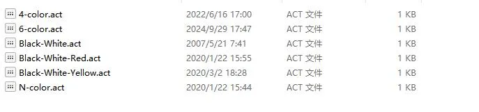
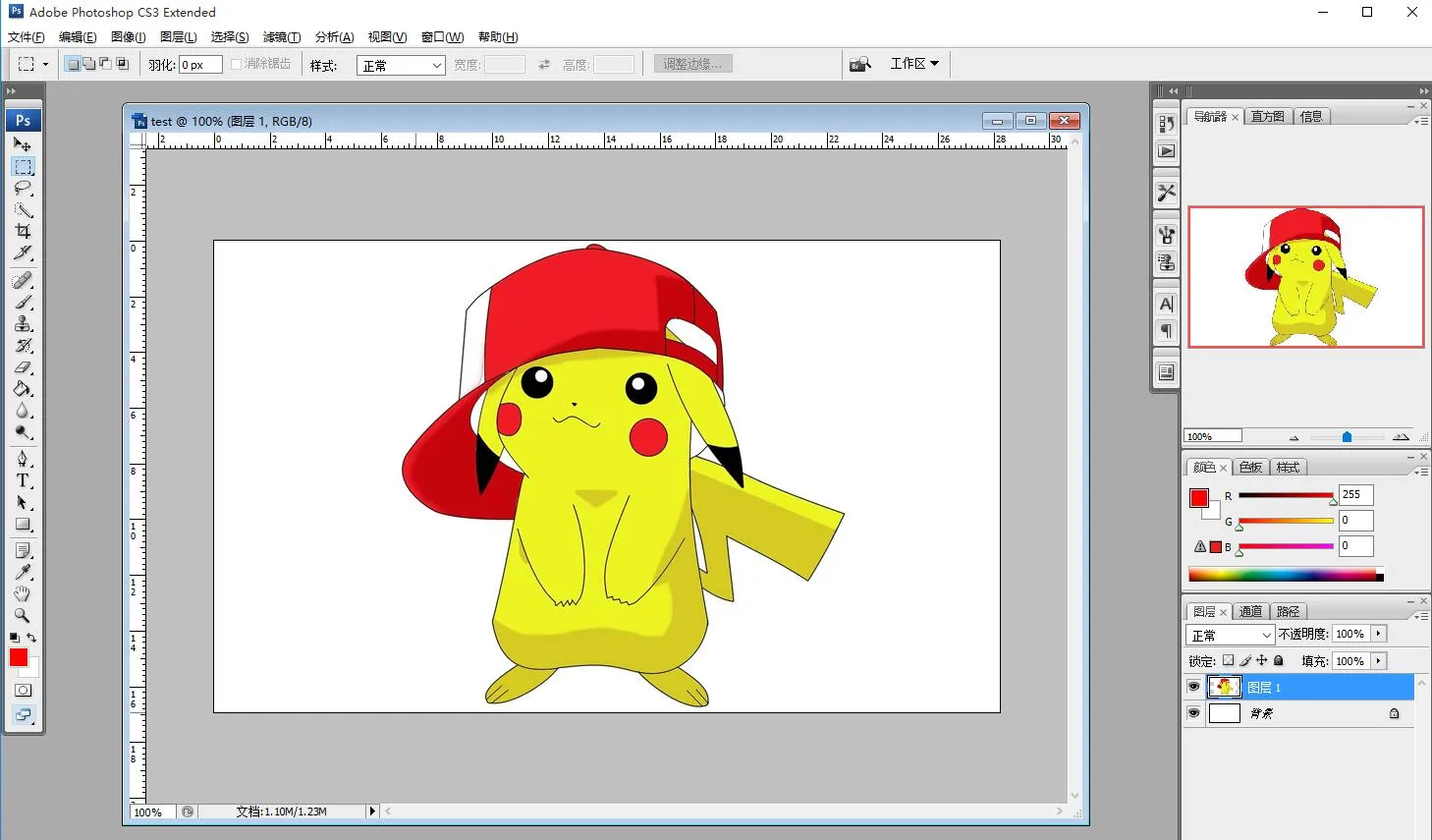
- Create a new Photoshop project, set the width and height according to the actual resolution of the e-Papre screen, and use RGB color in the color mode. If the screen resolution used is 800*480, change the width to 800 pixels and the height to 480 pixels.
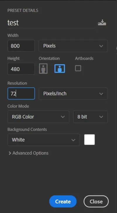
- Prepare the corresponding materials, copy them into the project, and adjust parameters such as size and contrast (similar to the steps involved in general Photoshop image processing).
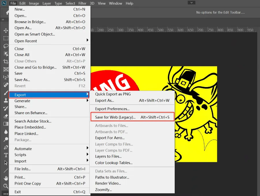
- Select File -> Save for Web in the format used for the Web and device.
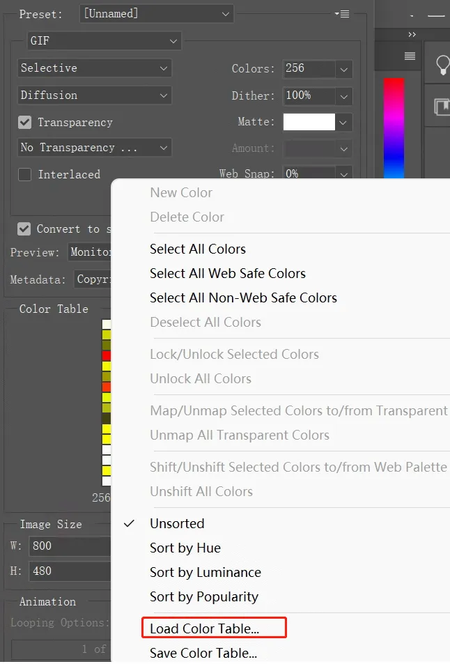
- Select Load Color Table as shown below. Load the Color Table provided in the Preparation section.
- For seven-color pictures, load N-color.act, then click Save to save as a gif file. Then convert it to BMP format.
For four-color pictures, load 4-color.act, then click Save to save as a gif file. Then convert it to BMP format.
For six-color pictures, load 6-color.act, then click Save to save as a gif file. Then convert it to BMP format.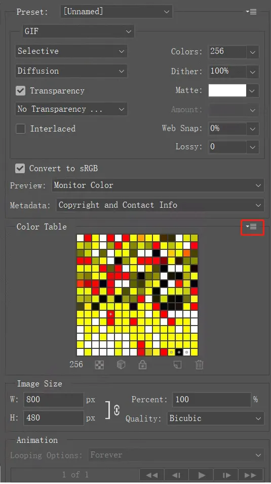
- Use Paint to open the gif file and save it as a 24-bit bmp image.
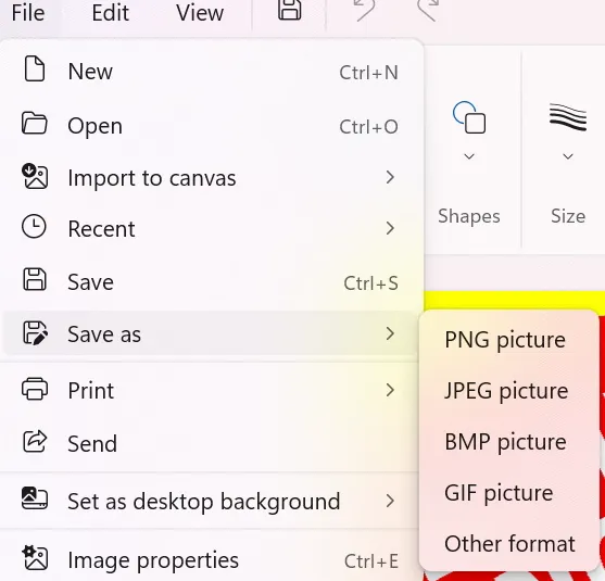
- The image is now ready. It can be used on the Raspberry Pi or e‑Paper Shield module via TF card, or converted into an array for use with other embedded devices as described in the next section.
- Create a new Photoshop project, set the width and height according to the actual resolution of the e-Papre screen, and use RGB color in the color mode. If the screen resolution used is 800*480, change the width to 800 pixels and the height to 480 pixels.
Image Data Conversion
Download Programs
- Four‑color conversion application: Four‑color image conversion application
- E6 full‑color conversion application: E6 full‑color image conversion application
- Seven‑color conversion application: Seven‑color image conversion application
- Source code: Program source code
This application is provided for your convenience and is open source, and our company does not provide technical support for it
Bug Resolution
- If you are using Windows 10/11 and have not installed VS (Microsoft Visual Studio) or other Microsoft development tools, you may encounter the following errors when using this program:
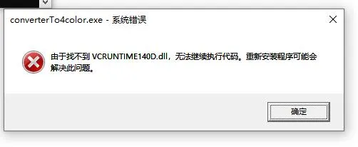
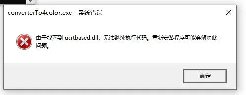
- This indicates that your computer is missing these two components. Solutions:
- Install VS (Microsoft Visual Studio) or other Microsoft development tools (e.g., Visual C++ Redistributable).
- Use the two component filesPlace these two files in the directory
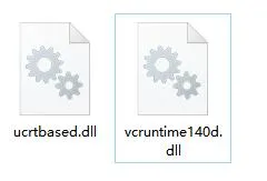
C:\Windows\System32, then restart your computer.
- Use the two component files
Conversion Steps
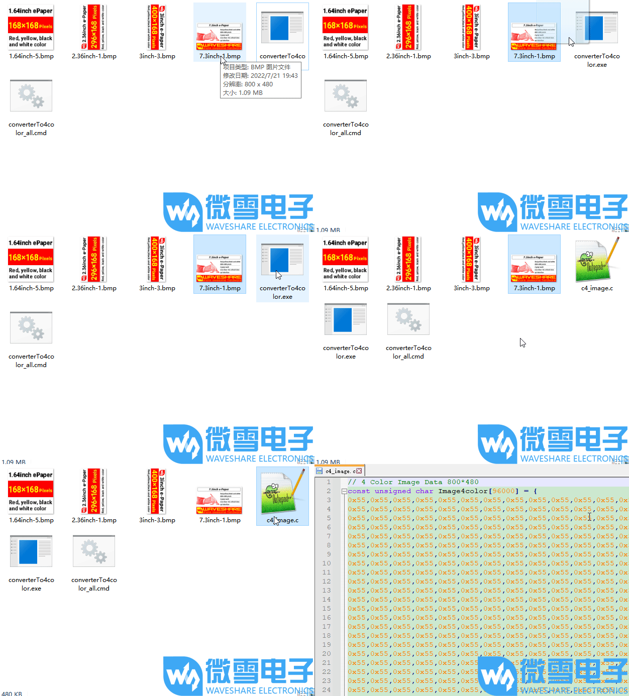
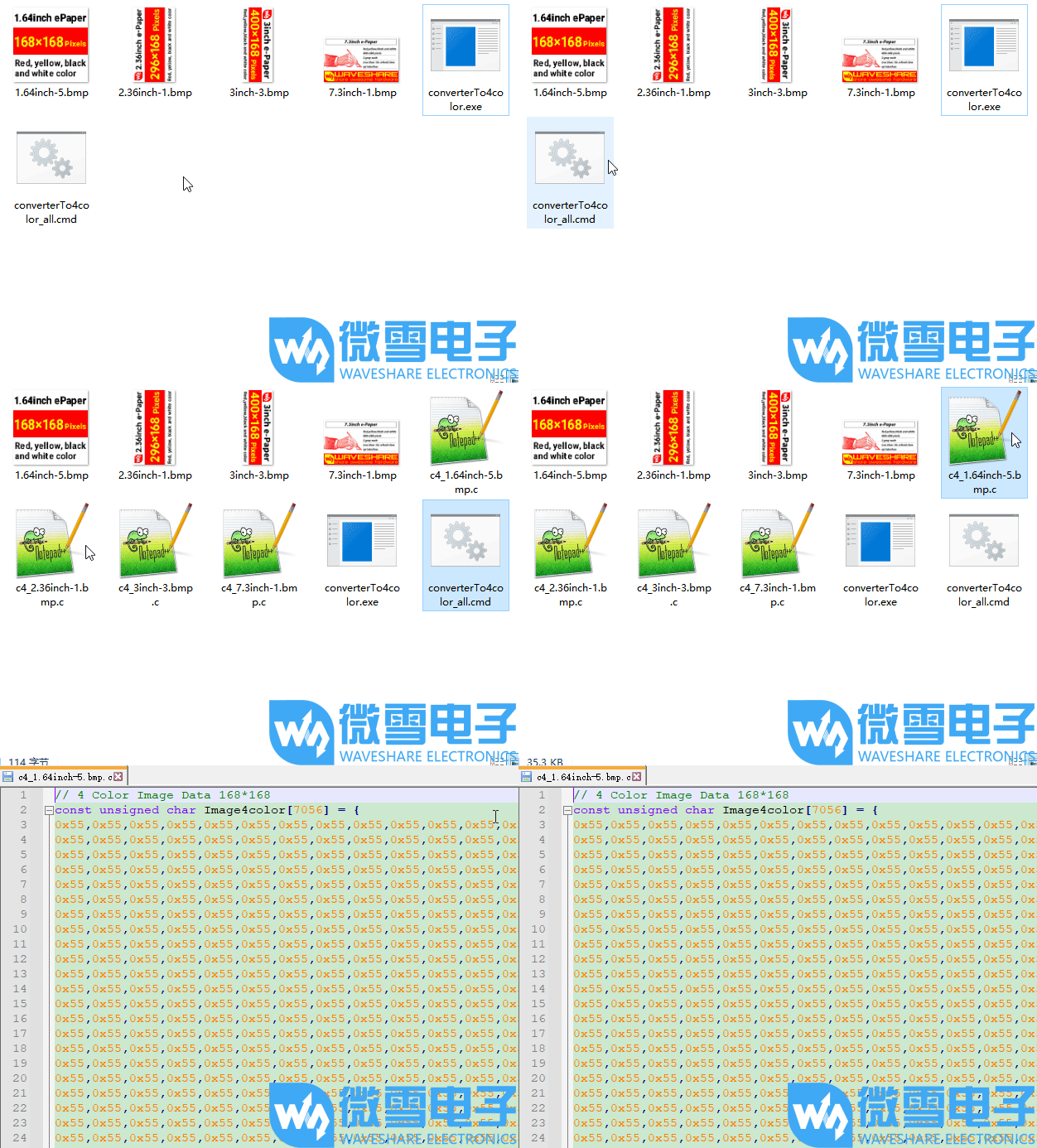
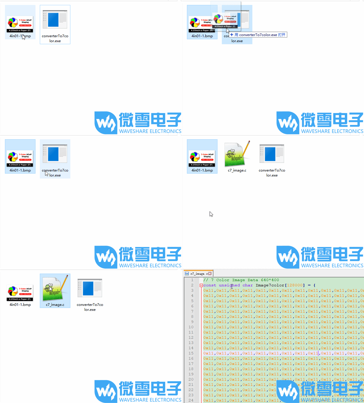
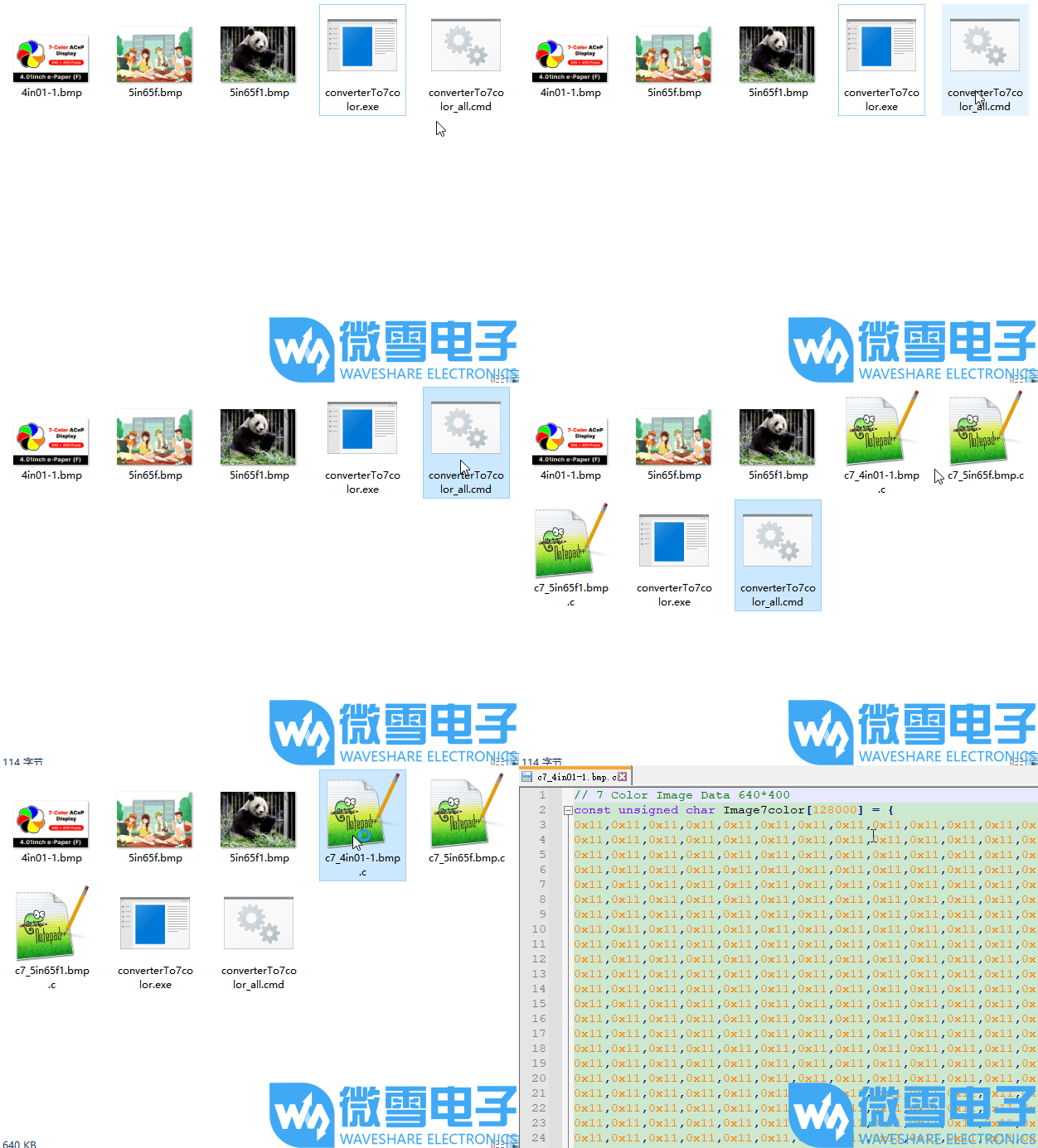
- Place the prepared image(s) and the corresponding .exe application in the same folder (multiple images can be placed).
- Drag and drop the image onto the .exe file; the program will convert the image into a .c file with a fixed name.
- Double‑click the .cmd file; the program will convert all images of the correct size in the folder into .c files with corresponding names.
- Four-color single image demonstration (click the image to see the demonstration)
- Four-color multiple image demonstration (click the image to view the demonstration)
- Seven-color single image demonstration (click the image to see the demonstration)
- Seven-color multiple image demonstration (click the image to view the demonstration)
Working with Raspberry Pi
Hardware Connection
- Connect using the 9PIN cable. Refer to the pin mapping table below:
- Raspberry Pi pin mapping
e-Paper Raspberry Pi Pin Mapping BCM2835 Pin Board Physical Pin Number VCC 3.3V 3.3V GND GND GND DIN MOSI 19 CLK SCLK 23 CS CE0 24 DC 25 22 RST 17 11 BUSY 24 18 PWR 18 12
- Raspberry Pi pin mapping
Enabling the SPI Interface
Open the Raspberry Pi terminal and enter the following command to access the configuration interface:
sudo raspi-configSelect Interfacing Options -> SPI -> Yes to enable the SPI interface
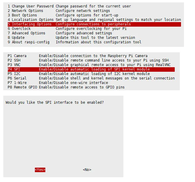
Reboot the Raspberry Pi:
sudo rebootCheck
/boot/config.txt, you should see thatdtparam=spi=onhas been written
To ensure SPI is not occupied, it is recommended to temporarily disable other driver overlays. Use
ls /dev/spi*to check the SPI occupancy. The terminal output/dev/spidev0.0and/dev/spidev0.1indicates that SPI is functioning normally.
Running the C Example
Install the lg library
#Open the Raspberry Pi terminal and run the following commands:wget https://github.com/joan2937/lg/archive/master.zipunzip master.zipcd lg-mastermakesudo make install# For more information, please refer to the source code: https://github.com/gpiozero/lgInstall gpiod library (optional)
#Open the Raspberry Pi terminal and run the following commands:sudo apt-get updatesudo apt install gpiod libgpiod-devInstall BCM2835 (optional)
#Open the Raspberry Pi terminal and run the following commands:wget http://www.airspayce.com/mikem/bcm2835/bcm2835-1.71.tar.gztar zxvf bcm2835-1.71.tar.gzcd bcm2835-1.71/sudo ./configure && sudo make && sudo make check && sudo make install# For more information, please refer to the official website: http://www.airspayce.com/mikem/bcm2835/Install wiringPi (optional)
#Open the Raspberry Pi terminal and run the following commands:sudo apt-get install wiringpi#For Raspberry Pi systems after May 2019 (those earlier may not require execution), an upgrade may be necessary:# project-downloads.drogon.net has been discontinued. Please use the GitHub method below for installation.# wget https://project-downloads.drogon.net/wiringpi-latest.deb# sudo dpkg -i wiringpi-latest.debgpio -v# Run gpio -v and version 2.52 will appear. If it does not appear, there is an installation error.#Bullseye branch system uses the following command:git clone https://github.com/WiringPi/WiringPicd WiringPi./buildgpio -v# Run gpio -v and version 2.60 will appear. If it does not appear, there is an installation error.Download the example (skip if already downloaded)
# Download and extract the example package from the resources page, then enter the directory:cd 9.7inch_e-Paper_E/example/RaspberryPi_JetsonNano/Alternative extraction method
sudo apt-get install p7zip-full7z x 9.7inch_e-Paper_E.zip -O./9.7inch_e-Paper_Ecd 9.7inch_e-Paper_E/example/RaspberryPi_JetsonNano/Download the program via GitHub (alternative method, skip if already downloaded)
- Accessing GitHub may not be very smooth at present. It is recommended to use the above method to download from our official website.git clone https://github.com/waveshareteam/9.7inch_e-Paper_E.gitcd 9.7inch_e-Paper_E/example/RaspberryPi_JetsonNano
- Accessing GitHub may not be very smooth at present. It is recommended to use the above method to download from our official website.
Compile the program (Note: -j4 uses 4 threads for compilation; you can modify the number)
# Now in 9.7inch_e-Paper_E/example/RaspberryPi_JetsonNanocd csudo make cleansudo make -j4Run the program
sudo ./epd
Running the Python Example
Install libraries
sudo apt-get updatesudo apt-get install python3-pipsudo apt-get install python3-pilsudo apt-get install python3-numpysudo pip3 install spidevInstall libraries (python2)
sudo apt-get updatesudo apt-get install python-pipsudo apt-get install python-pilsudo apt-get install python-numpysudo pip install spidevInstall gpiozero library (pre-installed by default, if not, install using the following commands)
sudo apt-get update# python3sudo apt install python3-gpiozero# python2sudo apt install python-gpiozeroDownload the example (skip if already downloaded)
# Download and extract the example package from the resources page, then enter the directory:cd 9.7inch_e-Paper_E/example/RaspberryPi_JetsonNano/Alternative extraction method
sudo apt-get install p7zip-full7z x 9.7inch_e-Paper_E.zip -O./9.7inch_e-Paper_Ecd 9.7inch_e-Paper_E/example/RaspberryPi_JetsonNano/Download the program via GitHub (alternative method, skip if already downloaded)
- Accessing GitHub may not be very smooth at present. It is recommended to use the above method to download from our official website.git clone https://github.com/waveshareteam/9.7inch_e-Paper_E.gitcd 9.7inch_e-Paper_E/example/RaspberryPi_JetsonNano
- Accessing GitHub may not be very smooth at present. It is recommended to use the above method to download from our official website.
Run the program
# Make sure you are in 9.7inch_e-Paper_E/example/RaspberryPi_JetsonNano/cd python/examples/python3 epd_9in7e_test.py
Working with Arduino
Hardware Connection
- Connect using the 9PIN cable. Refer to the pin mapping table below:
- Arduino pin mapping
e-Paper Arduino UNO Mega2560 VCC 3.3V/5V 5V GND GND GND DIN D11 D51 CLK D13 D52 CS D10 D10 DC D9 D9 RST D8 D8 BUSY D7 D7 PWR D6 D6
- Arduino pin mapping
Installing the IDE
Arduino IDE Windows Installation Tutorial
Running the Program
- Select a download source from the 9.7inch_e-Paper_E Example, then extract and enter the
9.7inch_e-Paper_Edirectory to see the following: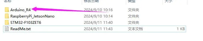
- Open the test program:
9.7inch_e-Paper_E\example\Arduino_R4\Arduino_R4.ino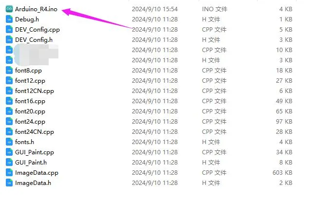
- In the Arduino IDE toolbar (Tools), select the corresponding Board and Port:
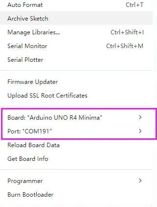
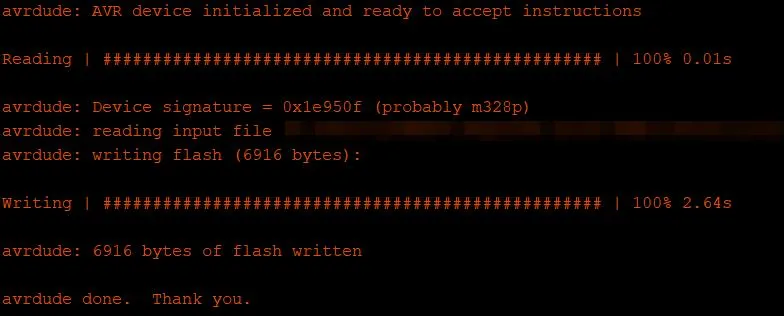
- Finally, click Upload. A successful upload is shown below (Arduino 1.8.13):
Working with Jetson Nano
Hardware Connection
Connect using the 9PIN cable. Refer to the pin mapping table below:
Jetson Nano pin mapping
e-Paper Jetson Nano Developer Kit BCM2835 Pin Board Physical Pin Number VCC 3.3V 3.3V GND GND GND DIN 10(SPI0_MOSI) 19 CLK 11(SPI0_SCK) 23 CS 8(SPI0_CS0) 24 DC 25 22 RST 17 11 BUSY 24 18 PWR 18 12
Running the C Example
Download the example (skip if already downloaded)
# Download and extract the example package from the resources page, then enter the directory:cd 9.7inch_e-Paper_E/example/RaspberryPi_JetsonNano/Alternative extraction method
sudo apt-get install p7zip-full7z x 9.7inch_e-Paper_E.zip -O./9.7inch_e-Paper_Ecd 9.7inch_e-Paper_E/example/RaspberryPi_JetsonNano/Download the program via GitHub (alternative method, skip if already downloaded)
- Accessing GitHub may not be very smooth at present. It is recommended to use the above method to download from our official website.git clone https://github.com/waveshareteam/9.7inch_e-Paper_E.gitcd 9.7inch_e-Paper_E/example/RaspberryPi_JetsonNano
- Accessing GitHub may not be very smooth at present. It is recommended to use the above method to download from our official website.
Compile the program (Note: -j4 uses 4 threads for compilation; you can modify the number)
# Now in 9.7inch_e-Paper_E/example/RaspberryPi_JetsonNanocd csudo make cleansudo make JETSON -j4Run the program
sudo ./epd
Running the Python Example
Install libraries
sudo apt-get updatesudo apt-get install python3-numpysudo apt-get install python3-pipsudo pip3 install Jetson.GPIODownload the example (skip if already downloaded)
# Download and extract the example package from the resources page, then enter the directory:cd 9.7inch_e-Paper_E/example/RaspberryPi_JetsonNano/Alternative extraction method
sudo apt-get install p7zip-full7z x 9.7inch_e-Paper_E.zip -O./9.7inch_e-Paper_Ecd 9.7inch_e-Paper_E/example/RaspberryPi_JetsonNano/Download the program via GitHub (alternative method, skip if already downloaded)
- Accessing GitHub may not be very smooth at present. It is recommended to use the above method to download from our official website.git clone https://github.com/waveshareteam/9.7inch_e-Paper_E.gitcd 9.7inch_e-Paper_E/example/RaspberryPi_JetsonNano
- Accessing GitHub may not be very smooth at present. It is recommended to use the above method to download from our official website.
Run the program
# Make sure you are in 9.7inch_e-Paper_E/example/RaspberryPi_JetsonNano/cd python/examples/python3 epd_9in7e_test.py
Working with STM32
Hardware Connection
Use a 9PIN cable to connect, please refer to the pin corresponding table below:
STM32 Pin Mapping
| e-Paper | STM32 |
|---|---|
| VCC | 3.3V |
| GND | GND |
| DIN | PA7 |
| CLK | PA5 |
| CS | PA4 |
| DC | PA2 |
| RST | PA1 |
| BUSY | PA3 |
| PWR | PA6 |
Running the Program
- Select a download source from the 9.7inch_e-Paper_E Example, then extract and enter the
9.7inch_e-Paper_Edirectory to see the following: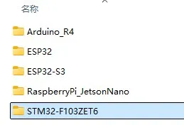
- Use Keil to open
epd-demo.uvprojxin the9.7inch_e-Paper_E/example/STM32-F103ZET6/MDK-ARMdirectory. - Open the Keil compile toolbar (usually already open):
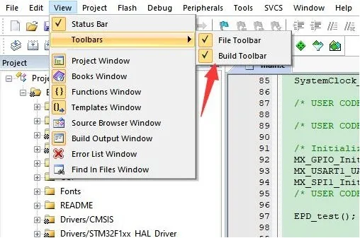
- Click Build.

- Ensure a suitable programmer is connected, then click Load to download the program to the microcontroller.
Working with ESP32
Hardware Connection
ESP32 Pin Mapping
| e-Paper | ESP32 | ESP32-S3 |
|---|---|---|
| VCC | 3.3V | 3.3V |
| GND | GND | GND |
| DIN | IO14 | IO11 |
| CLK | IO13 | IO12 |
| CS | IO15 | IO10 |
| DC | IO27 | IO13 |
| RST | IO26 | IO14 |
| BUSY | IO25 | IO4 |
| PWR | IO33 | IO5 |
Environment Configuration
Online installation requires the use of VPN software, while offline installation does not require the use of VPN software
Running the Program
- Select a download source from the 9.7inch_e-Paper_E Example, then extract and enter the
9.7inch_e-Paper_Edirectory to see the following: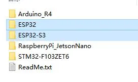
- Open the test program:
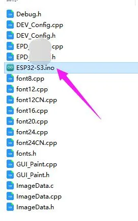
9.7inch_e-Paper_E\example\ESP32\ESP32.inoor9.7inch_e-Paper_E\example\ESP32-S3\ESP32-S3.ino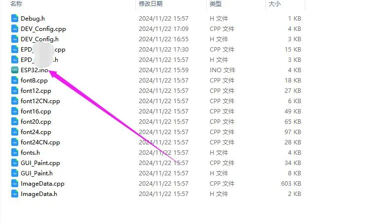
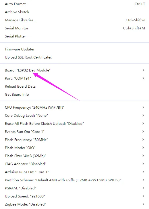
- In the Arduino IDE toolbar (Tools), select the corresponding Board and Port:
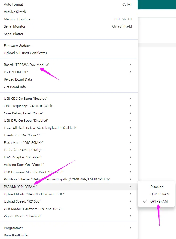
- If using a core like the ESP32-S3 with PSRAM, please enable PSRAM
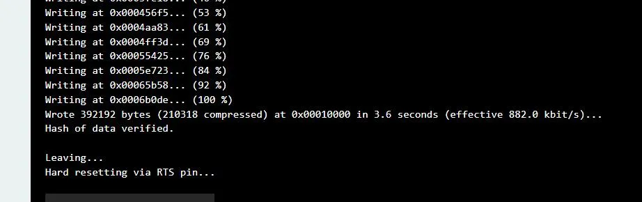
- Finally, click Upload. A successful upload is shown below (Arduino 2.2.1):
Resources
1. Example
2. Hardware Resources
3. Technical Manuals
4. Software Tools
- Arduino IDE Official Download Link
- Chinese Character Conversion Software
- Image2Lcd Image Bitmap Conversion Software
5. Other Resources
Related Links
Support
Monday-Friday (9:30-6:30) Saturday (9:30-5:30)
Email: services01@spotpear.com