




- sales/support
Google Chat:---
- sales
+86-0755-88291180
- sales01
sales@spotpear.com
- sales02
dragon_manager@163.com
- support
tech-support@spotpear.com
- CEO-Complaints
zhoujie@spotpear.com
- Only Tech-Support
WhatsApp:13246739196
- Purchase/Shipping/Refund
WhatsApp:13424403025
- HOME
- >
- ARTICLES
- >
- Common Moudle
- >
- ESP
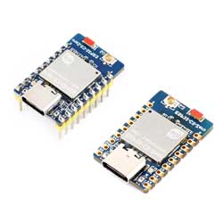
ESP32-C5-Zero User Guide
Features
- Equipped with a RISC-V 32-bit processor running at up to 240 MHz
- Integrated with 384KB SRAM, 320KB ROM, and 4MB Flash
- Integrates dual-band 2.4GHz & 5GHz Wi-Fi, Bluetooth 5.0 (LE), and IEEE 802.15.4 (supporting Zigbee 3.0 and Thread) wireless communication, delivering excellent RF performance.
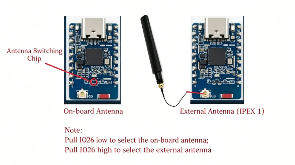
- Onboard antenna switching chip, supports onboard antenna or external antenna (IPEX-1)
- Features a reversible USB Type-C connector.
- Exposes rich peripheral interfaces with a castellated module design, facilitating soldering and integration onto user-designed carrier boards.
- Supports various low-power operating states, allowing flexible adjustment between communication range, data rate, and power consumption to meet the power requirements of various application scenarios.
Resource Interface
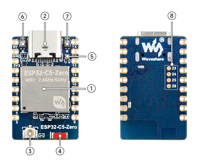

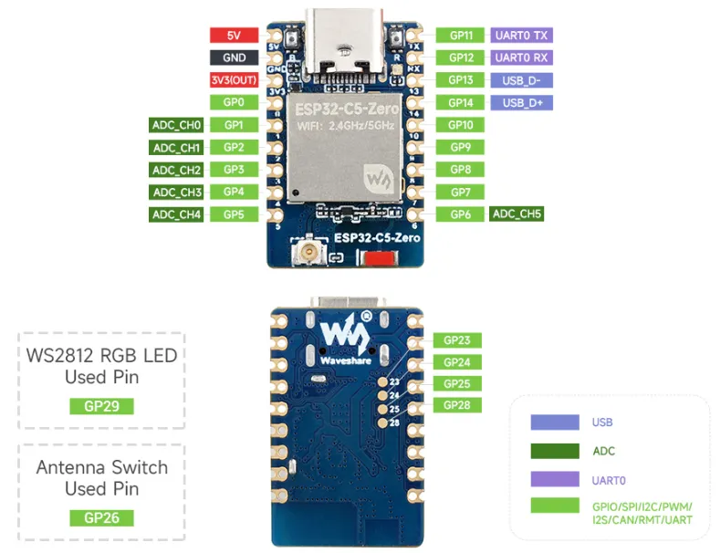
Pinout Definition
Antenna Switching
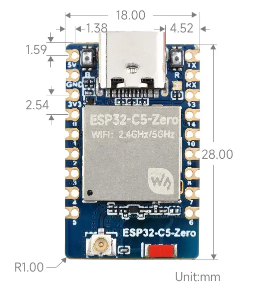
Dimensions
Working with Arduino
This chapter contains the following sections. Please read as needed:
Arduino Getting Started
New to Arduino ESP32 development and looking for a quick start? We have prepared a comprehensive Getting Started Tutorial for you.
- Section 0: Getting to Know ESP32
- Section 1: Installing and Configuring Arduino IDE
- Section 2: Arduino Basics
- Section 3: Digital Output/Input
- Section 4: Analog Input
- Section 5: Pulse Width Modulation (PWM)
- Section 6: Serial Communication (UART)
- Section 7: I2C Communication
- Section 8: SPI Communication
- Section 9: Wi-Fi Basics
- Section 10: Web Server
- Section 11: Bluetooth
- Section 12: LVGL GUI Development
- Section 13: Comprehensive Project
Note: This tutorial uses the ESP32-S3-Zero as a reference example, and all hardware code is based on its pinout. Before you start, we recommend checking the pinout of your development board to ensure the pin configuration is correct.
Setting Up Development Environment
1. Installing and Configuring Arduino IDE
Please refer to the tutorial Installing and Configuring Arduino IDE to download and install the Arduino IDE and add ESP32 support.
Installation Steps: For installation methods, please refer to: Arduino Library Management Tutorial.
2. Example
The Arduino examples are located in the Arduino directory of the example package.
| Example | Basic Description |
|---|---|
| 01_GPIO | Control the logic level of the exposed GPIO pins |
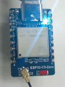
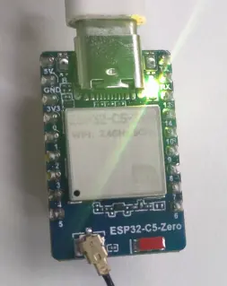
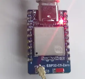
| 02_BlinkRGB | Implement a breathing LED effect on the RGB LED |
| 03_GetchipID | Obtain and print ESP32-C5 chip hardware information every three seconds, including chip model, revision, core count, and chip ID |
| 04_BLE | Use the ESP32-C5-Zero development board to connect to BLE beacons and receive broadcast data |
| 05_UART | Implement UART communication using the ESP32-C5-Zero development board |
| 06_WIFI_AP | Configure the ESP32-C5-Zero development board as an AP hotspot (2.4G), allowing other Wi-Fi devices to connect |
| 07_WIFI_STA | Connect to a specified Wi-Fi network, print connection information, fetch weather data via an API, and support automatic reconnection upon Wi-Fi disconnection |
| 08_WIFI_StaticIP | Use the ESP32-C5-Zero development board to connect to Wi-Fi with a static IP address |
01_GPIO
Code
01_GPIO.ino
void loop() {
  REG_WRITE(GPIO_OUT_REG, REG_READ(GPIO_OUT_REG) ^ gpio_low);
  REG_WRITE(GPIO_OUT1_REG, REG_READ(GPIO_OUT1_REG) ^ gpio_high);
  delay(300);
}
Code Analysis
REG_WRITE()combined withREG_READ()toggles the GPIO output registers bitwise, allowing multiple pins to change state simultaneously.delay(300)controls the toggling rhythm, making it easier to observe with external LEDs or an oscilloscope.
02_BlinkRGB
Code
02_BlinkRGB.ino
void loop() {
  static uint8_t wheel_pos = 0;      // Current color position (0-255)
  static uint32_t last_update_ms = 0;

  const uint32_t now = millis();

  if (now - last_update_ms >= 20) {
    last_update_ms = now;

    // Calculate and set the color
    set_wheel_color(wheel_pos);

    // Increment position and wrap around at 255
    wheel_pos++;
  }
}
Code Analysis
set_wheel_color(wheel_pos)computes an RGB color based on the current wheel position and writes it to the onboard LED.wheel_pos++continuously increments the color index, creating a smooth color‑cycling effect with a 20ms refresh interval.
Operation Result
03_GetchipID
Code
03_GetchipID.ino
void loop() {
  const uint64_t mac = ESP.getEfuseMac();
  uint32_t chip_id = 0;
  for (uint8_t i = 0; i < 24; i = (uint8_t)(i + 8)) {
    chip_id |= (uint32_t)(((mac >> (40 - i)) & 0xff) << i);
  }

  Serial.printf("ESP32-C5-Zero Chip model = %s Rev %d\n", ESP.getChipModel(), ESP.getChipRevision());
  Serial.printf("This chip has %d cores\n", ESP.getChipCores());
  Serial.print("Chip ID: ");
  Serial.println(chip_id);
  delay(3000);
}
Code Analysis
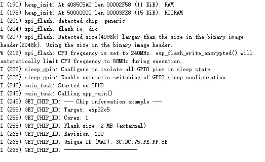
ESP.getEfuseMac()reads the factory‑flashed MAC address of the chip and further combines it into a simplifiedchip_id.- The code outputs the chip model, revision, and core count via the serial port, making it easy to quickly identify the current board.
Operation Result
04_BLE
Code
04_BLE.ino
void setup() {
  Serial.begin(115200);

  NimBLEDevice::init("ESP32-C5-Zero");

  NimBLEAdvertising *advertising = NimBLEDevice::getAdvertising();

  NimBLEAdvertisementData scan_response;
  scan_response.setName("ESP32-C5-Zero");   // This is the name shown on the phone
  advertising->setScanResponseData(scan_response);

  const bool ok = advertising->start();
  if (ok) {
    Serial.println("BLE advertising started");
  }else{
    Serial.println("BLE advertising start failed");
  }
}
Code Analysis
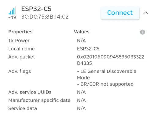
NimBLEDevice::init()initializes the BLE stack and sets the device name shown during advertising.advertising->start()starts advertising, allowing the board to be discovered by phones or other BLE devices.
Operation Result
 |
|---|
05_UART
Code
05_UART.ino
void loop() {
  while (Serial1.available() > 0) {
    Serial1.write(Serial1.read());
  }
  delay(1);
}
Code Analysis
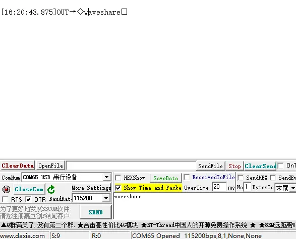
Serial1.available()checks whether new data is present in the UART receive buffer.- Any data read is immediately sent back via
Serial1.write(), implementing a basic serial loopback test.
Operation Result
 |
|---|
06_WIFI_AP
Code
06_WIFI_AP.ino
void setup() {
  Serial.begin(115200);

  // Best practice: Register the event handler BEFORE starting the AP
  // so you don't miss any immediate connection events.
  WiFi.onEvent(on_wifi_event);

  // Start the Access Point
  Serial.println("Starting WiFi Access Point...");
  if (!WiFi.softAP(ssid, password)) {
    Serial.println("Failed to start WiFi AP! Halting system.");
    while (true); // Halt if AP fails to start
  }

  Serial.println("WiFi Access Point initialized successfully!");
  Serial.print("AP SSID: ");
  Serial.println(ssid);
  Serial.print("AP IP Address: ");
  Serial.println(WiFi.softAPIP()); // Also print the AP's own IP address
}
Code Analysis
WiFi.softAP(ssid, password)starts the access point mode, making the development board work as a Wi‑Fi hotspot.WiFi.softAPIP()reads the hotspot's local IP address, facilitating subsequent connection testing with phones or computers.
Operation Result
 |
|---|
07_WIFI_STA
Code
07_WIFI_STA.ino
void setup() {
  // Initialize serial communication
  Serial.begin(115200);
  while (!Serial);  // Wait for serial port to connect

  // Connect to WiFi
  Serial.println("Connecting to WiFi...");
  WiFi.begin(ssid, password);

  // Wait for WiFi connection
  while (WiFi.status() != WL_CONNECTED) {
    delay(500);
    Serial.print(".");
  }

  // Print connection success message with WiFi details
  Serial.println("\n");
  Serial.println("=====================================");
  Serial.println("WiFi connection successful!");
  Serial.print("Connected to SSID: ");
  Serial.println(ssid);
  Serial.print("With password: ");
  Serial.println(password);
  Serial.print("Assigned IP address: ");
  Serial.println(WiFi.localIP());
  Serial.println("=====================================\n");
}
Code Analysis
WiFi.begin(ssid, password)attempts to connect to the specified router, with a loop that continuously checks the connection status.- After a successful connection,
WiFi.localIP()prints the assigned IP address to confirm network connectivity.
Operation Result

08_WIFI_StaticIP
Code
08_WIFI_StaticIP.ino
void loop() {
  static uint32_t last_check_ms = 0;
  const uint32_t now = millis();
  if ((uint32_t)(now - last_check_ms) < 5000) {
    delay(10);
    return;
  }
  last_check_ms = now;

  // Periodically check Wi-Fi connection and auto-reconnect
  if (WiFi.status() != WL_CONNECTED) {
    Serial.println("Wi-Fi disconnected, attempting reconnection...");
    WiFi.begin(ssid, password); // Re-initiate connection
    uint8_t retry = 0;
    uint32_t retry_start_ms = millis();
    uint32_t retry_dot_ms = retry_start_ms;
    while (WiFi.status() != WL_CONNECTED && retry < 5) {
      const uint32_t now2 = millis();
      if ((uint32_t)(now2 - retry_dot_ms) >= 1000) {
        retry_dot_ms = now2;
        Serial.print('.');
        retry++;
      }
      delay(10);
    }
    if (WiFi.status() == WL_CONNECTED) {
      Serial.println("\nReconnected to Wi-Fi!");
      Serial.print("Current IP: ");
      Serial.println(WiFi.localIP());
    }
  }
  delay(10);
}
Code Analysis
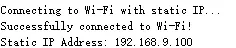
- This code checks the network connection status every 5 seconds to avoid frequent reconnection attempts in the main loop.
- When the Wi‑Fi is disconnected, it re‑calls
WiFi.begin()to initiate a new connection and prints the current IP address upon successful reconnection.
Operation Result
 |
|---|
Working with ESP-IDF
This chapter includes the following sections, please read as needed:
ESP-IDF Getting Started
New to ESP32 ESP-IDF development and looking to get started quickly? We have prepared a general Getting Started Tutorial for you.
- Section 1: Environment Setup
- Section 2: Running Examples
- Section 3: Creating a Project
- Section 4: Using Components
- Section 5: Debugging
- Section 6: FreeRTOS
- Section 7: Peripherals
- Section 8: Wi-Fi Programming
- Section 9: BLE Programming
Please Note: This tutorial uses the ESP32-S3-Zero as a teaching example, and all hardware code is based on its pinout. Before you start, it is recommended that you check the pinout of your development board to ensure the pin configuration is correct.
Setting Up Development Environment
The following guide uses Windows as an example, demonstrating development using VS Code + the ESP-IDF extension. macOS and Linux users should refer to the official documentation.
The screenshots in this section use ESP-IDF V5.5.2 as an example. When installing, please select the ESP-IDF version that matches your board's example.
Install the ESP-IDF Development Environment
Download the installation manager from the ESP-IDF Installation Manager page. This is Espressif's latest cross-platform installer. The following steps demonstrate how to use its offline installation feature.
Click the Offline Installer tab on the page, then select Windows as the operating system and the ESP-IDF version you need (the version shown in the screenshot is for reference only — choose the version that fits your actual needs).
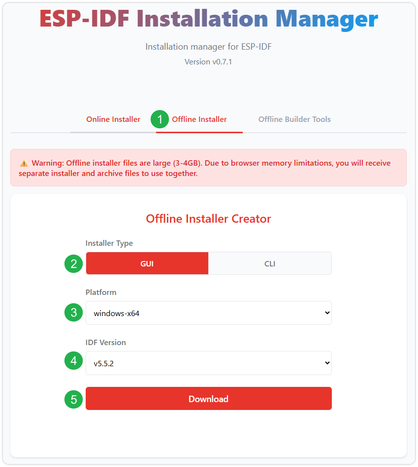
After confirming your selection, click the download button. The browser will automatically download two files: the ESP-IDF Offline Package (.zst) and the ESP-IDF Installer (.exe).
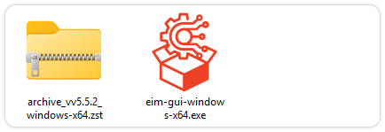
Please wait for both files to finish downloading.
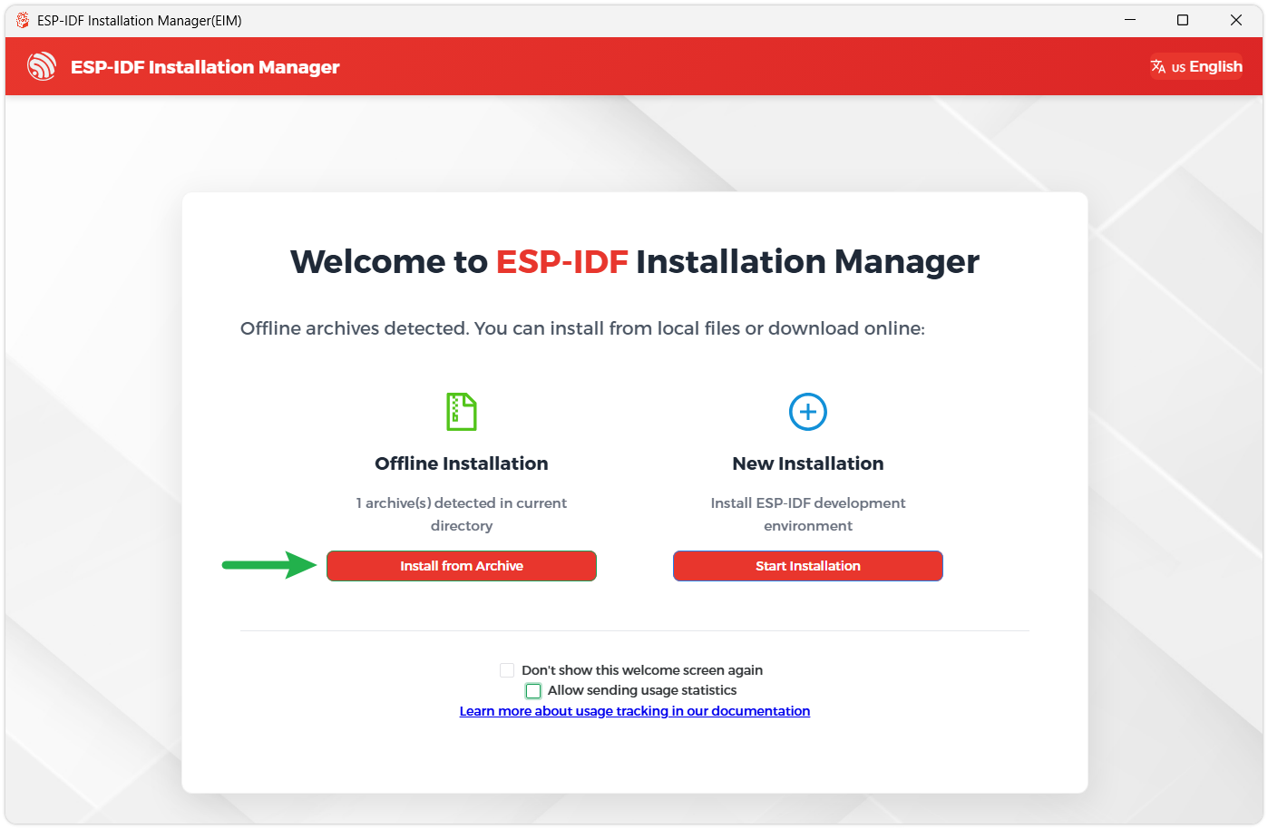
Once the download is complete, double-click to run the ESP-IDF Installer (eim-gui-windows-x64.exe).
The installer will automatically detect if the offline package exists in the same directory. Click Install from archive.
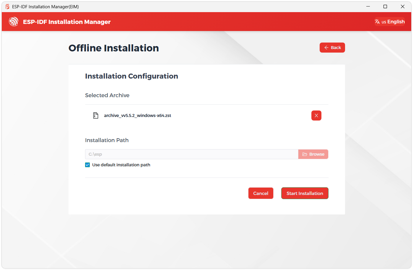
Next, select the installation path. We recommend using the default path. If you need to customize it, ensure the path does not contain Chinese characters or spaces. Click Start installation to proceed.
When you see the following screen, the ESP-IDF installation is successful.
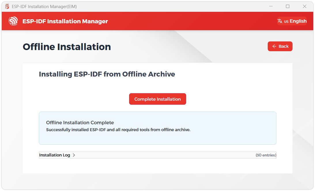
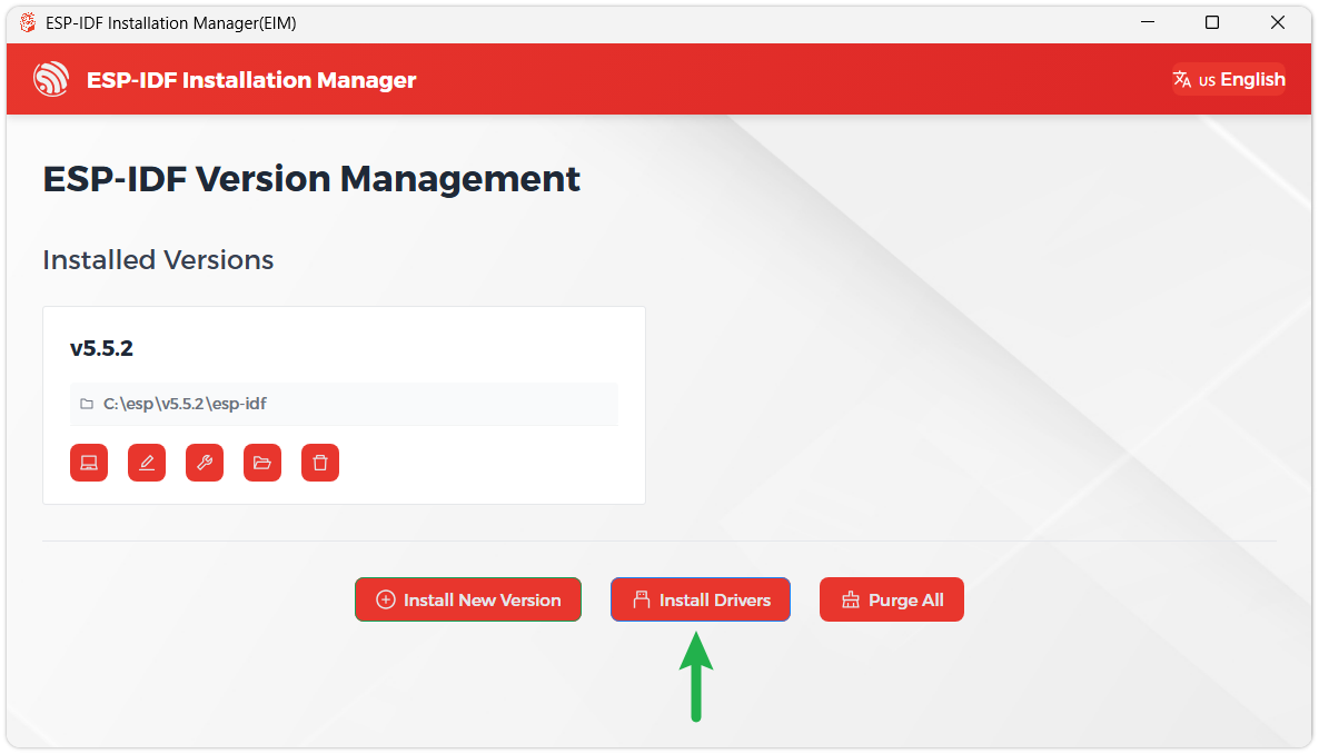
We recommend installing the drivers as well. Click Finish installation, then select Install driver.
Install Visual Studio Code and the ESP-IDF Extension
Download and install Visual Studio Code.
During installation, it is recommended to check Add "Open with Code" action to Windows Explorer file context menu to facilitate opening project folders quickly.
In VS Code, click the Extensions icon
 in the Activity Bar on the side (or use the shortcut Ctrl + Shift + X) to open the Extensions view.
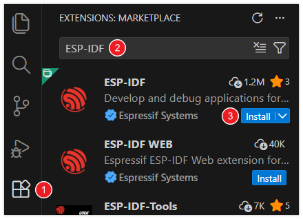
Enter ESP-IDF in the search box, locate the ESP-IDF extension, and click Install.
For ESP-IDF extension versions ≥ 2.0, the extension will automatically detect and recognize the ESP-IDF environment installed in the previous steps, requiring no manual configuration.
Example
The ESP-IDF examples are located in the ESP-IDF directory of the example package.
| Example | Basic Description |
|---|---|
| 01_GPIO | Control the logic level of the exposed GPIO pins |
| 02_BlinkRGB | Implement a breathing LED effect on the RGB LED |
| 03_GetchipID | Obtain and print hardware information of the ESP32-C5-Zero chip, including model, revision, core count, and chip ID |
| 04_BLE | Use the ESP32-C5-Zero development board to connect to BLE beacons and receive broadcast data |
| 05_UART | Implement UART communication using the ESP32-C5-Zero development board |
| 06_WIFI_AP | Configure the ESP32-C5-Zero development board as an AP hotspot (2.4G), allowing other Wi‑Fi devices to connect |
| 07_WIFI_STA | Connect to a specified Wi‑Fi network and print connection information |
| 08_WIFI_StaticIP | Use the ESP32-C5-Zero development board to connect to Wi-Fi with a static IP address |
| 09_ZIGBEE | Use Zigbee on the ESP32-C5-Zero development board to control the onboard LED on/off |
| 10_Mem_Security | Demonstrate memory security features on the ESP32-C5-Zero development board |
01_GPIO
Code
01_GPIO.ino
void app_main(void)
{
    // Configure all selected GPIOs as push-pull outputs
    gpio_config_t io_conf = {
        .intr_type = GPIO_INTR_DISABLE,
        .mode = GPIO_MODE_OUTPUT,
        .pin_bit_mask = GPIO_OUTPUT_PIN_SEL,
        .pull_down_en = 0,
        .pull_up_en = 0,
    };
    ESP_ERROR_CHECK(gpio_config(&io_conf));

    int output_level = 0;
    size_t gpio_count = sizeof(gpio_pins) / sizeof(gpio_pins[0]);

    ESP_LOGI(log_tag, "Initialization done. Start toggling GPIO pins synchronously...");

    while (true) {
        // Set all selected pins to the same level
        for (size_t i = 0; i < gpio_count; i++) {
            ESP_ERROR_CHECK(gpio_set_level(gpio_pins[i], output_level));
        }

        // Flip output level for next cycle
        output_level = !output_level;
        vTaskDelay(pdMS_TO_TICKS(500));
    }
}
Code Analysis
- The code first iterates through selected GPIO pins, setting them to the same output level, then toggles the level synchronously using
output_level = !output_level. vTaskDelay(pdMS_TO_TICKS(500))controls the blink period for easy observation of GPIO output changes.
02_BlinkRGB
Code
02_BlinkRGB.ino
    while (true) {
        // Calculate current color
        led_strip_set_wheel(led_strip, wheel_pos);

        // Refresh LED
        led_strip_refresh(led_strip);

        // Increment position (uint8_t automatically wraps to 0 after 255)
        wheel_pos++;

        vTaskDelay(pdMS_TO_TICKS(20));
    }
Code Analysis
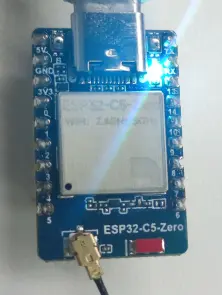
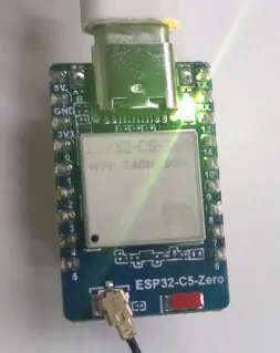
led_strip_set_wheel()computes the current color based onwheel_pos, ideal for creating a rainbow cycle effect.- A 20 ms delay after each
led_strip_refresh()makes the color transitions appear smoother.
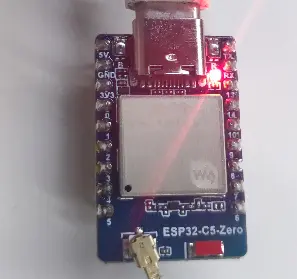
Operation Result
03_GetchipID
Code
03_GetchipID.ino
void app_main(void)
{
    ESP_LOGI(log_tag, "--- Chip information example ---");

    /* Get chip information */
    esp_chip_info_t chip_info;
    esp_chip_info(&chip_info);

    /* Print target and core count */
    ESP_LOGI(log_tag, "Target: %s", CONFIG_IDF_TARGET);
    ESP_LOGI(log_tag, "Cores: %d", chip_info.cores);

    /* Get and print flash size */
    uint32_t flash_size;
    esp_flash_get_size(NULL, &flash_size);
    ESP_LOGI(log_tag, "Flash size: %" PRIu32 " MB (%s)",
           flash_size / (1024 * 1024),
           (chip_info.features & CHIP_FEATURE_EMB_FLASH) ? "embedded" : "external");

    /* Print revision */
    ESP_LOGI(log_tag, "Revision: %d", chip_info.revision);

    /* Use default MAC address as a unique ID */
    uint8_t mac[6];
    esp_efuse_mac_get_default(mac);
    ESP_LOGI(log_tag, "Unique ID (MAC): %02X:%02X:%02X:%02X:%02X:%02X",
           mac[0], mac[1], mac[2], mac[3], mac[4], mac[5]);

    ESP_LOGI(log_tag, "------------------------");

    /* Run forever */
    while (true) {
        vTaskDelay(pdMS_TO_TICKS(5000));
    }
}
Code Analysis
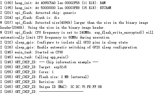
esp_chip_info()reads basic hardware information such as core count and chip revision.esp_efuse_mac_get_default()retrieves the default MAC address, which can be used as a unique device identifier.
Operation Result
04_BLE
Code
04_BLE.ino
void app_main(void) {
    // 1. Initialize NVS (required for Bluetooth stack)
    if (nvs_flash_init() != ESP_OK) {
        nvs_flash_erase();
        nvs_flash_init();
    }

    // 2. Initialize Bluetooth Controller
    esp_bt_controller_config_t bt_cfg = BT_CONTROLLER_INIT_CONFIG_DEFAULT();
    esp_bt_controller_init(&bt_cfg);
    esp_bt_controller_enable(ESP_BT_MODE_BLE);

    // 3. Initialize Bluedroid Stack
    esp_bluedroid_init();
    esp_bluedroid_enable();

    // 4. Register GAP callback and configure advertising data
    esp_ble_gap_register_callback(gap_event_handler);
    esp_ble_gap_config_adv_data_raw(adv_data, sizeof(adv_data));

    ESP_LOGI(TAG, "BLE stack initialized, setting up advertising...");
}
Code Analysis
- The code first initializes NVS, the Bluetooth controller, and the Bluedroid stack – all prerequisites for BLE advertising.
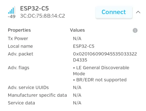
esp_ble_gap_config_adv_data_raw()configures raw advertising data, after which the device becomes discoverable by external scanners.
Operation Result
 |
|---|
05_UART
Code
05_UART.ino
void app_main(void) {
    uart_config_t uart_cfg = {
        .baud_rate = 115200,
        .data_bits = UART_DATA_8_BITS,
        .parity    = UART_PARITY_DISABLE,
        .stop_bits = UART_STOP_BITS_1,
        .flow_ctrl = UART_HW_FLOWCTRL_DISABLE,
        .source_clk = UART_SCLK_DEFAULT,
    };

    ESP_ERROR_CHECK(uart_param_config(UART_PORT, &uart_cfg));

    ESP_ERROR_CHECK(uart_driver_install(UART_PORT, BUF_SIZE * 2, BUF_SIZE * 2, 0, NULL, 0));

    ESP_ERROR_CHECK(uart_set_pin(UART_PORT, TXD_PIN, RXD_PIN, UART_PIN_NO_CHANGE, UART_PIN_NO_CHANGE));

    xTaskCreate(rx_task, "uart_rx", 4096, NULL, 10, NULL);
    xTaskCreate(tx_task, "uart_tx", 4096, NULL, 9, NULL);
}
Code Analysis
uart_param_config(),uart_driver_install()anduart_set_pin()configure the UART parameters, driver, and pin mapping respectively.- Finally,
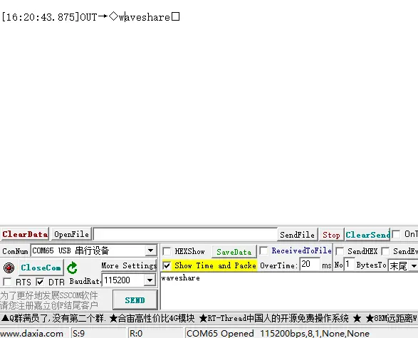
xTaskCreate()starts separate receive and transmit tasks, allowing UART reception and transmission to run concurrently.
Operation Result
 |
|---|
06_WIFI_AP
Code
06_WIFI_AP.ino
void app_main(void) {
    // 1. Initialize NVS (required for AP mode as well).
    if (nvs_flash_init() != ESP_OK) {
        nvs_flash_erase();
        nvs_flash_init();
    }

    // 2. Initialize network stack and create the default AP netif.
    esp_netif_init();
    esp_event_loop_create_default();
    esp_netif_create_default_wifi_ap();

    // 3. Initialize WiFi driver and register event handler.
    wifi_init_config_t cfg = WIFI_INIT_CONFIG_DEFAULT();
    esp_wifi_init(&cfg);
    esp_event_handler_instance_register(WIFI_EVENT, ESP_EVENT_ANY_ID, &wifi_handler, NULL, NULL);

    // 4. Configure AP parameters with designated initializer.
    wifi_config_t ap_cfg = {
        .ap = {
            .ssid = SSID,
            .password = PWD,
            .ssid_len = 0,             // Use null-terminated SSID string length.
            .channel = 1,
            .max_connection = 4,
            .authmode = WIFI_AUTH_WPA2_PSK
        },
    };

    // Switch to open mode when password is empty.
    if (PWD[0] == '\0') ap_cfg.ap.authmode = WIFI_AUTH_OPEN;

    esp_wifi_set_mode(WIFI_MODE_AP);
    esp_wifi_set_config(WIFI_IF_AP, &ap_cfg);
    esp_wifi_start();

    ESP_LOGI(TAG, "AP Mode started. SSID: %s", SSID);
}
Code Analysis
- This code configures the board as an AP (Access Point) using
esp_wifi_set_mode(WIFI_MODE_AP)andesp_wifi_set_config(). - If the password is empty, it automatically switches to open‑mode hotspot for quick connection testing.
Operation Result
 |
|---|
07_WIFI_STA
Code
07_WIFI_STA.ino
void app_main(void) {
  // 1. Initialize NVS (WiFi configuration needs to be stored in NVS)
  if (nvs_flash_init() != ESP_OK) {
    nvs_flash_erase();
    nvs_flash_init();
  }

  // 2. Initialize network stack and underlying drivers
  esp_netif_init();
  esp_event_loop_create_default();
  esp_netif_create_default_wifi_sta();

  wifi_init_config_t cfg = WIFI_INIT_CONFIG_DEFAULT();
  esp_wifi_init(&cfg);

  // 3. Register event handlers (handle all WiFi and IP related events)
  esp_event_handler_instance_register(WIFI_EVENT, ESP_EVENT_ANY_ID,
                                      &wifi_handler, NULL, NULL);
  esp_event_handler_instance_register(IP_EVENT, IP_EVENT_STA_GOT_IP,
                                      &wifi_handler, NULL, NULL);

  // 4. Initialize GPIO26 as output
  gpio_reset_pin(GPIO_NUM_26);
  gpio_set_direction(GPIO_NUM_26, GPIO_MODE_OUTPUT);

  GPIO26_ON();
  // 4. Configure and start WiFi
  wifi_config_t wifi_cfg = {
      .sta =
          {
              .ssid = SSID,
              .password = PWD,
          },
  };
  esp_wifi_set_mode(WIFI_MODE_STA);
  esp_wifi_set_config(WIFI_IF_STA, &wifi_cfg);
  esp_wifi_start();

  ESP_LOGI(TAG, "WiFi station started.");
}
Code Analysis
esp_netif_create_default_wifi_sta()creates the default STA network interface for connecting to a router.- After registering Wi‑Fi and IP event callbacks, the program can execute corresponding logic upon successful connection or disconnection.
Operation Result

08_WIFI_StaticIP
Code
08_WIFI_StaticIP.ino
    esp_netif_ip_info_t ip_info = {
        .ip.addr = ipaddr_addr("192.168.1.77"),
        .gw.addr = ipaddr_addr("192.168.1.1"),
        .netmask.addr = ipaddr_addr("255.255.255.0")
    };
Code Analysis
- The
esp_netif_ip_info_tstructure is used to set a static IP address, gateway, and subnet mask in one go. - This approach is suitable for scenarios where a fixed device address is required, making it easy to access the board via a known IP address on the local network.
Operation Result
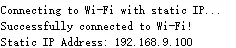 |
|---|
09_ZIGBEE
- Prepare two ESP32-C5-Zero development boards, ensuring they are powered correctly and ready for program flashing.
- Connect the first development board to the computer. Use the flashing tool to flash the HA_on_off_light program onto this board (this program controls the RGB LED). After flashing, keep the board powered on.
- Connect the second development board to the computer. Use the flashing tool to flash the HA_on_off_switch program onto this board (this program implements the control function via the BOOT button). After flashing, keep the board powered on.
Code
09_ZIGBEE.ino
void app_main(void)
{
    esp_zb_platform_config_t config = {
        .radio_config = ESP_ZB_DEFAULT_RADIO_CONFIG(),
        .host_config = ESP_ZB_DEFAULT_HOST_CONFIG(),
    };
    ESP_ERROR_CHECK(nvs_flash_init());
    ESP_ERROR_CHECK(esp_zb_platform_config(&config));

    xTaskCreate(esp_zb_task, "Zigbee_main", 4096, NULL, 5, NULL);
}
Code Analysis
esp_zb_platform_config()initializes the Zigbee platform layer, preparing the radio and host configuration.xTaskCreate(esp_zb_task, ...)runs the Zigbee main task independently, facilitating network control logic expansion.
Operation Result
10_Mem_Security
Code
10_Mem_Security.ino
    print_status();
    print_privilege();
    test_hw_crypto();
    test_tee_apm();
Code Analysis
- These lines display the current security status, privilege information, and test hardware cryptography as well as TEE/APM related functions.
- Useful for quickly verifying whether the chip's security features are initialized correctly.
Working with MicroPython
This chapter contains the following sections. Please read as needed:
MicroPython Getting Started
New to ESP32 MicroPython development and looking for a quick start? We have prepared a comprehensive ESP32 MicroPython Getting Started Tutorial for you.
- Section 1: Setup Development Environment
- Section 2: Basics
- Section 3: GPIO Digital Output/Input
- Section 4: ADC Analog Input
- Section 5: PWM Output
- Section 6: UART Communication
- Section 7: I2C Communication
- Section 8: SPI Communication
- Section 9: Wi-Fi Basic
- Section 10: Web Server
- Section 11: Bluetooth
- Section 12: Comprehensive Project
Note: This tutorial uses the ESP32-S3-Zero as a teaching example, and all hardware code is based on its pinout. Before proceeding, we recommend checking the pinout diagram of your specific development board to ensure the pin configuration is correct.
Setting Up Development Environment
1. Flash MicroPython Firmware and Configure Thonny
Please refer to the Set Up MicroPython Development Environment to flash the MicroPython firmware.
2. Other Tips
ESP32-C5-Zero MicroPython firmware download link: https://micropython.org/download/ESP32_GENERIC_C5/
If you flash the MicroPython firmware using the Espressif Flash Download Tool for the ESP32-C5-Zero, the flash address is
0x0.
| Example | Basic Description |
|---|---|
| 01_GPIO | Controls a total of 20 specified GPIO pins to cycle through HIGH/LOW level switching in sequence, and prints the level change status of each pin via serial port |
| 02_BlinkRGB | Controls an RGB LED to create a waterfall light dynamic effect |
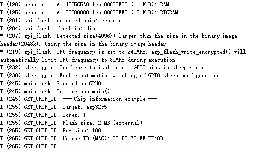
| 03_GetchipID | Obtain and print ESP32-C5 chip hardware information every three seconds, including chip model, revision, core count, and chip ID |
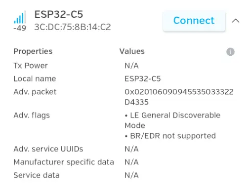
| 04_BLE | Use the ESP32-C5-Zero development board to connect to BLE beacons and receive broadcast data |
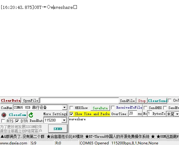
| 05_UART | Implement UART communication using the ESP32-C5-Zero development board |
| 06_WIFI_AP | Configure the ESP32-C5-Zero development board as an AP hotspot (2.4G), allowing other Wi‑Fi devices to connect |
| 07_WIFI_STA | Connect to Wi‑Fi using DHCP on the ESP32-C5-Zero development board and obtain an IP address |
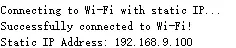
| 08_WIFI_StaticIP | Connect to a specified Wi‑Fi network, print connection information, then switch to a static IP configuration after a successful connection, facilitating local network debugging and access |
01_GPIO
Code
GPIO.py
for i in range(13):
    pins.append(Pin(i, Pin.OUT))

while True:
    for p in pins:
        p.value(1)
    time.sleep(0.5)

    for p in pins:
        p.value(0)
    time.sleep(0.5)
Code Analysis
- The code first configures GPIO 0 to 12 as output pins, then sets them all high or low in a loop to create a blinking effect.
time.sleep(0.5)controls the on/off rhythm, making it easy to observe the pin output.
02_BlinkRGB
Code
BlinkRGB.py
def wheel(pos):
    if pos < 85:
        return (pos * 3, 255 - pos * 3, 0)
    elif pos < 170:
        pos -= 85
        return (255 - pos * 3, 0, pos * 3)
    else:
        pos -= 170
        return (0, pos * 3, 255 - pos * 3)

while True:
    for i in range(256):
        np[0] = wheel(i)
        np.write()
        time.sleep(0.02)
Code Analysis
wheel(pos)returns different RGB combinations based on the position value, used to generate a rainbow gradient effect.np.write()refreshes the color data to the LED, and the loop creates a flowing color‑changing effect.
Operation Result
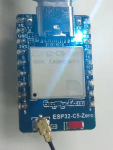 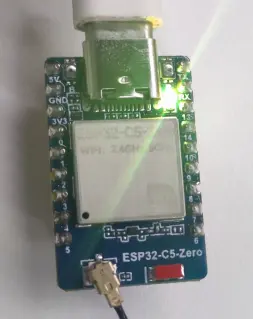 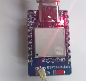 |
|---|
03_GetchipID
Code
GetchipID.py
wlan = network.WLAN(network.STA_IF)
wlan.active(True)

mac = wlan.config('mac')
chip_id = ubinascii.hexlify(mac).decode()

print("Chip Unique ID:", chip_id)
Code Analysis
network.WLAN(network.STA_IF)enables the wireless card in STA mode.- The obtained
macis converted to a hex string usingubinascii.hexlify()and printed as a unique ID.
Operation Result
 |
|---|
04_BLE
Code
BLE.py
def adv_payload(name, tx_power=-4):
    name = name.encode()

    payload = bytearray()

    # Flags
    payload += struct.pack("BB", 2, 0x01) + b"\x06"

    # TX Power
    payload += struct.pack("BBb", 2, 0x0A, tx_power)

    # Name
    payload += struct.pack("BB", len(name) + 1, 0x09) + name

    return payload

ble.gap_advertise(200_000, adv_payload("ESP32-C5-Zero-BLE"))

while True:
    time.sleep(1)
Code Analysis
adv_payload()assembles the BLE advertising packet, including the device name and transmit power.- After
ble.gap_advertise()starts broadcasting, external devices can discover the BLE device by its name.
Operation Result
 |
|---|
05_UART
Code
UART.py
# UART1
uart = UART(
    1,
    baudrate=115200,
    tx=Pin(11),
    rx=Pin(12)
)

print("UART-Init")

while True:
    uart.write("Waveshare\r\n")
    time.sleep(1)
Code Analysis
- The code initializes UART1 using
UART(1, ...)and maps TX/RX to the specified pins. - In the main loop, it sends a string every second, providing a basic serial connectivity test.
Operation Result
 |
|---|
06_WIFI_AP
Code
WIFI_AP.py
# Brief pause to ensure the AP is fully initialized
time.sleep(1)

# Print the AP details in a formatted way
print("-" * 30)
print("AP (Access Point) Started Successfully!")
print("SSID:", ap.config("essid"))
print("Password:", PASSWORD)
# ap.ifconfig() returns a tuple: (IP, Subnet Mask, Gateway, DNS)
# Index [0] is the IP address
print("IP Address:", ap.ifconfig()[0])
print("-" * 30)
Code Analysis
- This code prints the SSID, password, and IP address after the hotspot is started, confirming that AP mode is working.
ap.ifconfig()[0]retrieves the current IP address of the hotspot.
Operation Result
 |
|---|
07_WIFI_STA
Code
WIFI_STA.py
def connect_wifi():
    sta = network.WLAN(network.STA_IF)
    sta.active(True)

    if not sta.isconnected():
        print("Connecting to WiFi...")
        sta.connect(SSID, PASSWORD)

        while not sta.isconnected():
            time.sleep(0.5)
            print(".", end="")
Code Analysis
sta.connect(SSID, PASSWORD)initiates the connection, and the following loop waits until the connection is established.- This approach is suitable for example demonstrations, showing the device connecting to Wi‑Fi.
Operation Result

08_WIFI_StaticIP
Code
WIFI_StaticIP.py
if sta.isconnected():
    # Step 2: After connection, overwrite configuration to lock static IP
    sta.ifconfig((STATIC_IP, SUBNET_MASK, GATEWAY, DNS))

    print("-" * 30)
    print("WiFi connected successfully!")
    print("Connected to SSID:", SSID)
    print("Static IP locked to:", sta.ifconfig()[0])
    print("Gateway:", sta.ifconfig()[2])
    print("-" * 30)
else:
    print("Connection failed. Please check hotspot status, credentials, or signal strength.")
Code Analysis
- After a successful connection,
sta.ifconfig(...)manually writes the static IP configuration, overriding the DHCP assignment. - This ensures the device always uses a fixed address after connecting, facilitating local network debugging and access.
Operation Result
 |
|---|
Resources
1. Hardware Resources
Development Board Design Files
2. Technical Manuals
ESP32-C5 Chip Official Manuals
Datasheets
3. Software Development Resources
Support
Monday-Friday (9:30-6:30) Saturday (9:30-5:30)
Email: services01@spotpear.com
[Tutorial Navigation]
- Features
- Working with Arduino
- Arduino Getting Started
- Setting Up Development Environment
- Working with ESP-IDF
- ESP-IDF Getting Started
- Setting Up Development Environment
- Example
- Working with MicroPython
- MicroPython Getting Started
- Setting Up Development Environment
- Resources
- Support