




- sales/support
Google Chat:---
- sales
+86-0755-88291180
- sales01
sales@spotpear.com
- sales02
dragon_manager@163.com
- support
tech-support@spotpear.com
- CEO-Complaints
zhoujie@spotpear.com
- Only Tech-Support
WhatsApp:13246739196
- Purchase/Shipping/Refund
WhatsApp:13424403025
- HOME
- >
- ARTICLES
- >
- Common Moudle
- >
- ESP
ESP32-C5-LCD-1.47 User Guide
Overview
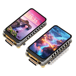
The ESP32-C5-LCD-1.47 is a microcontroller development board that supports 2.4 GHz / 5 GHz Wi-Fi 6, Bluetooth 5 (LE), and IEEE 802.15.4. It features an onboard 1.47inch LCD, TF card slot, RGB LED, and common peripheral interfaces, making it suitable for ESP32-C5 HMI, wireless communication, and embedded display applications.
| SKU | Product |
|---|---|
| 34961 | ESP32-C5-LCD-1.47 |
| 34960 | ESP32-C5-LCD-1.47-M |
Features
- Equipped with ESP32-C5FH4, RISC-V 32-bit processor running at up to 240 MHz, with a low-power processor running at up to 48 MHz
- Supports 2.4 GHz / 5 GHz Wi-Fi 6, Bluetooth 5 (LE), Zigbee 3.0 and Thread 1.4
- Onboard 320 KB ROM, 384 KB HP SRAM, 16 KB LP SRAM, and 4 MB Flash
- Onboard 1.47inch LCD screen, 172 × 320 resolution, 262K colors
- Onboard USB-C port supporting native ESP32-C5 USB download, debugging, and serial communication, depending on firmware configuration
- Onboard TF card slot for external TF card storage of images or files
- Onboard WS2812 RGB LED
- Adapting multiple GPIO pins via an 18PIN header
Onboard Resources
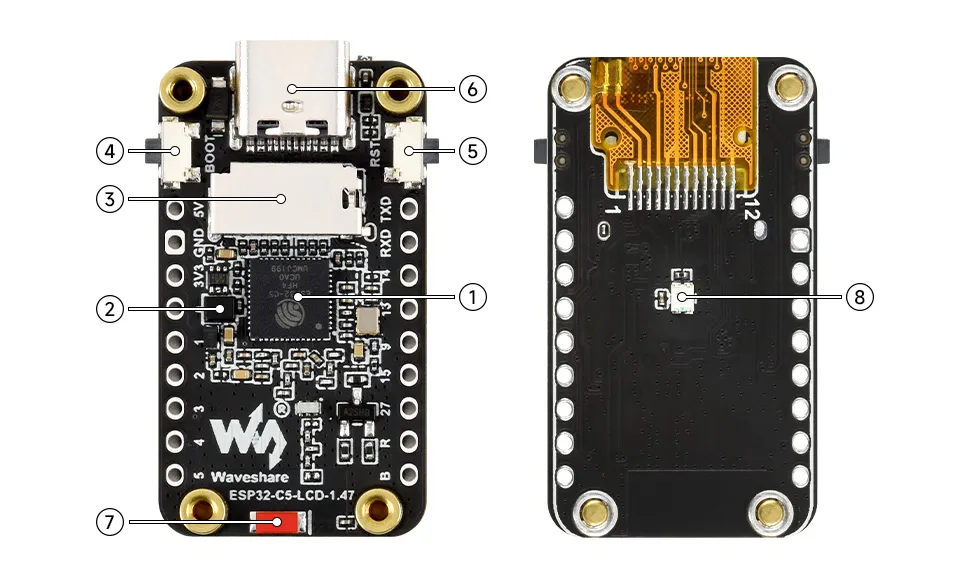
- ESP32-C5FH4
- MP1605GTF Step-down DC-DC converter, 1A output (Max.)
- TF card slot
- BOOT button
- RESET button
- USB Type-C
- Onboard ceramic antenna
- WS2812 RGB LED
Interface Overview
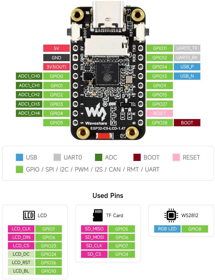
LCD
LCD Pin ESP32-C5 LCD_CLK GPIO7 LCD_DIN GPIO6 LCD_CS GPIO23 LCD_DC GPIO24 LCD_RST GPIO26 LCD_BL GPIO10 RGB LED
RGB LED ESP32-C5 WS2812 GPIO8 TF Card
TF Card ESP32-C5 MISO GPIO5 MOSI GPIO6 CLK GPIO7 CS GPIO4 UART0
UART0 ESP32-C5 TX GPIO11 RX GPIO12 USB
USB ESP32-C5 D+ GPIO14 D- GPIO13
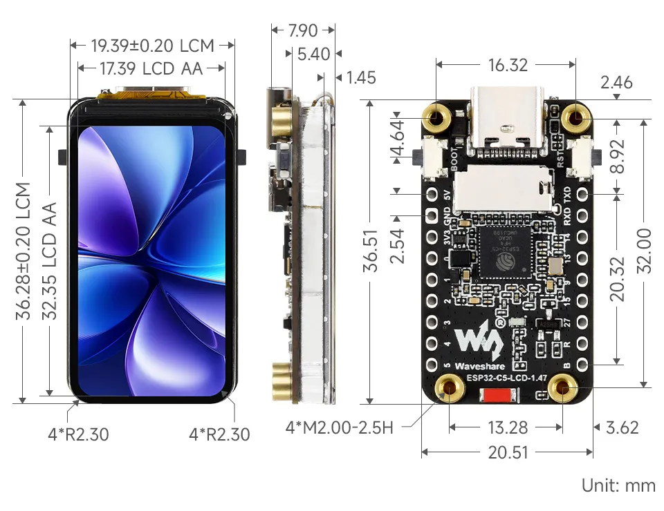
Product Dimensions
Product Specifications
| Parameter | Value |
|---|---|
| Interface | USB Type-C |
| Main Chip | ESP32-C5FH4 |
| Flash | 4 MB |
| Screen Type | TFT |
| Screen Size | 1.47 inches |
| Screen Resolution | 172 × 320 |
| Screen Interface | SPI |
| Screen Controller | ST7789 |
| Touch | None |
| Onboard Devices | TF, WS2812 RGB LED |
| Broken-out Interface | 18PIN header |
Working with Arduino
This chapter contains the following sections. Please read as needed:
Arduino Getting Started
New to Arduino ESP32 development and looking for a quick start? We have prepared a comprehensive Getting Started Tutorial for you.
- Section 0: Getting to Know ESP32
- Section 1: Installing and Configuring Arduino IDE
- Section 2: Arduino Basics
- Section 3: Digital Output/Input
- Section 4: Analog Input
- Section 5: Pulse Width Modulation (PWM)
- Section 6: Serial Communication (UART)
- Section 7: I2C Communication
- Section 8: SPI Communication
- Section 9: Wi-Fi Basics
- Section 10: Web Server
- Section 11: Bluetooth
- Section 12: LVGL GUI Development
- Section 13: Comprehensive Project
Note: This tutorial uses the ESP32-S3-Zero as a reference example, and all hardware code is based on its pinout. Before you start, we recommend checking the pinout of your development board to ensure the pin configuration is correct.
Setting Up the Development Environment
1. Installing and Configuring the Arduino IDE
Please refer to the tutorial Installing and Configuring the Arduino IDE to download and install the Arduino IDE.
2. Installing the ESP32 Development Board
- ESP32-related boards require the "esp32 by Espressif Systems" board support package.
- For installation instructions, refer to the Arduino Board Manager Tutorial.
- For the ESP32-C5-LCD-1.47, select a board package version that includes ESP32-C5 support.
3. Installing the Libraries
The example programs require the following Arduino libraries. If you are installing libraries manually in Arduino IDE, refer to the Arduino Library Manager Tutorial.
| Library Name | Description |
|---|---|
| GFX Library for Arduino | LCD graphics driver library, used as GFX_Library_for_Arduino in the examples |
| lvgl 9.5.0 | Graphics library, used for LVGL-related examples |
LVGL has version dependencies with the example code. Please use lvgl 9.5.0 to avoid compilation failures or display issues caused by version mismatches.
Example
The example programs are located in the
examples/arduinodirectory of the resource package. Before flashing, ensure that the board model, USB port, and partition scheme are correctly configured.The root directory of the resource package already contains the
librariesfolder. Before compiling examples in Arduino IDE, open "File" > "Preferences" and set the "Sketchbook location" to the root directory of the resource package, i.e., theesp32-c5-lcd-1.47folder that contains bothlibrariesandexamples. After setting, restart Arduino IDE, then open the examples to compile and flash.
Board Resources
| Feature | Resource | GPIO or Notes |
|---|---|---|
| LCD | ST7789, SPI, 172 × 320, RGB565 | SCLK GPIO7, MOSI GPIO6, CS GPIO23, DC GPIO24, RST GPIO26 |
| LCD Backlight | LEDC PWM | GPIO10 |
| TF | SDSPI | SCLK GPIO7, MOSI GPIO6, MISO GPIO5, CS GPIO4 |
| RGB LED | WS2812B, 1 LED | GPIO8, RGB order |
| SPIFFS | Internal Flash file system | Select a partition scheme that includes SPIFFS |
| Wi-Fi | ESP32-C5 built-in wireless | No extra GPIO needed |
Arduino Project Parameter Settings
- Open Arduino IDE.
- In "Tools" > "Board", select the ESP32-C5 board.
- Select the currently connected USB port.
- To view serial output, enable USB CDC or use the corresponding serial configuration as described in the example notes.
- Before compiling
06_spiffs_rwand08_board_showcase, select a partition scheme that includes SPIFFS.
When using arduino-cli to compile, refer to the following commands:
arduino-cli lib install "GFX Library for Arduino"
arduino-cli lib install "lvgl@9.5.0"
arduino-cli compile --fqbn esp32:esp32:esp32c5 arduino/02_lvgl_hello
Example List
| Example Directory | Description |
|---|---|
01_lcd_panel_basic | Initialize the LCD using GFX_Library_for_Arduino and draw color blocks |
02_lvgl_hello | Start LVGL 9.5.0 and display a basic interface on the LCD |
03_backlight_fade | Use LEDC to adjust the LCD backlight and display the brightness value via LVGL |
04_ws2812_rgb | Use rgbLedWrite() to control the onboard WS2812B RGB LED to cycle through different colors |
05_sdcard_rw | Show a TF status page and perform file write and read-back verification |
06_spiffs_rw | Mount SPIFFS and perform file write and read-back verification in internal Flash |
07_wifi_scan | Scan nearby Wi-Fi networks and output the scan results with strong signals via serial |
08_board_showcase | Comprehensive demonstration of LCD, WS2812B, SPIFFS, TF card, and Wi-Fi status |
01_lcd_panel_basic
Example Description
- This example initializes the ST7789 LCD using
GFX_Library_for_Arduinowithout starting LVGL. - The LCD first displays a multi-color stripe background, then shows a moving color block to check display and partial refresh functionality.
Hardware Connection
- Connect the development board to the computer.
- This example uses only the onboard LCD and backlight; no external modules are required.
Code Analysis
setup(): Initializes serial, LCD backlight, and LCD driver, then callsdraw_color_bars()to draw the background.init_backlight(): Configures LEDC PWM backlight output on GPIO10.draw_color_bars(): Draws multiple color stripes across the screen width.loop(): Periodically callsdraw_motion_frame()to refresh the area where the moving color block is located.
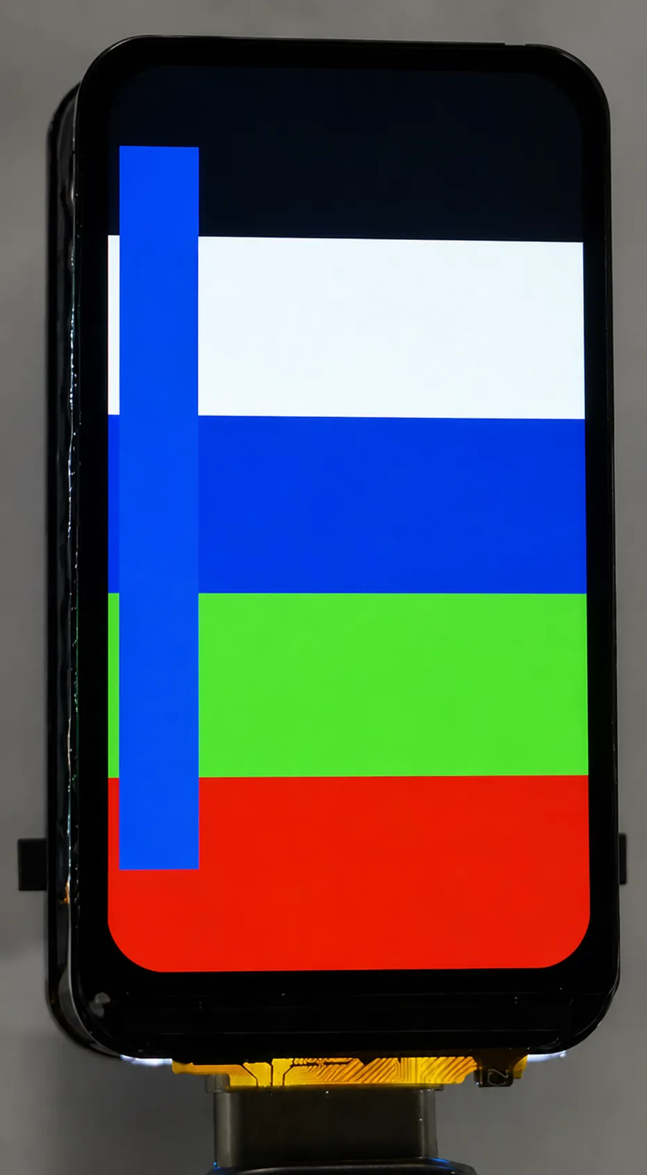
Running Effect
- The LCD displays a multi-color stripe background with a color block moving up and down continuously.
02_lvgl_hello
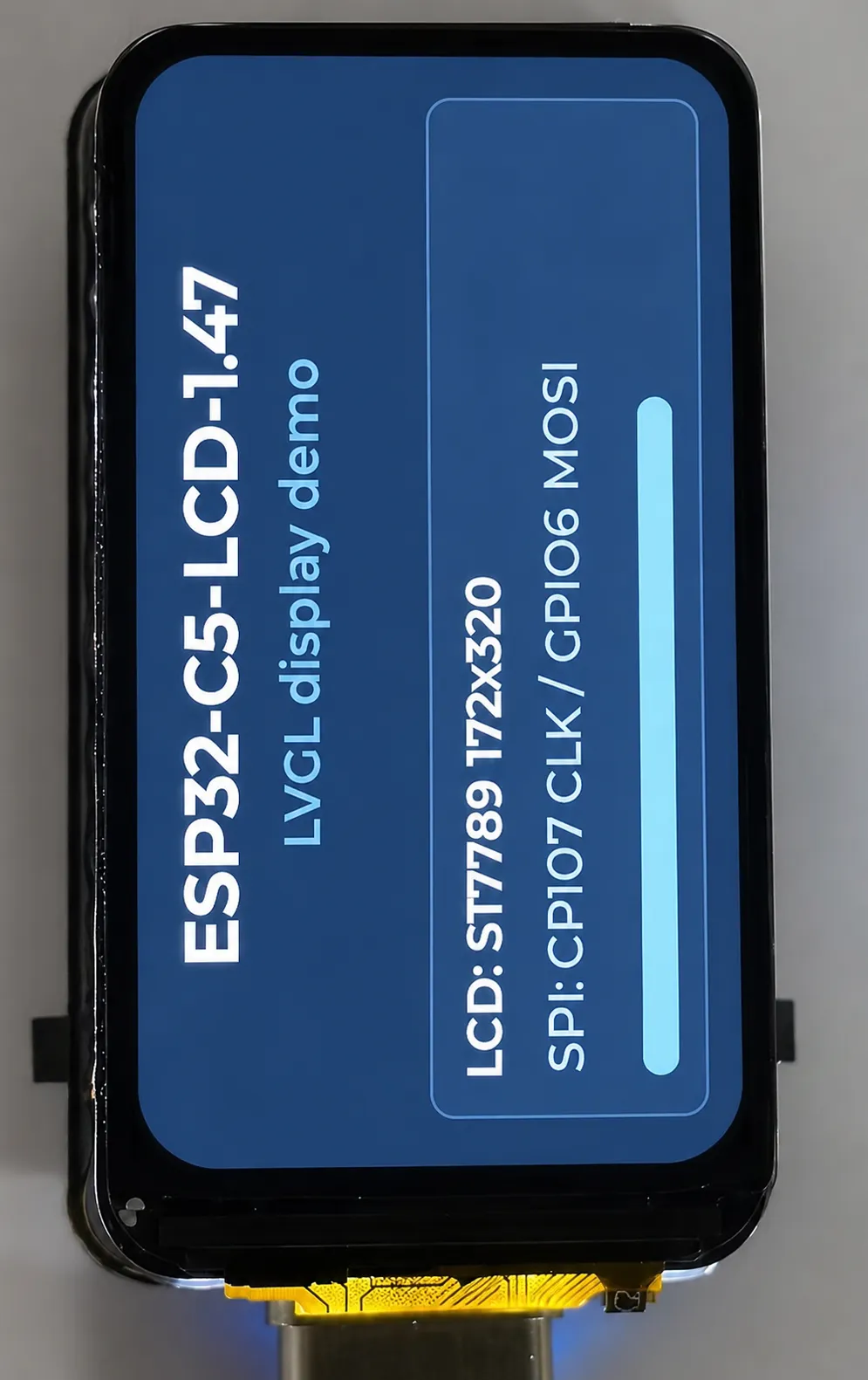
Example Description
- This example starts LVGL 9.5.0 and outputs the LVGL display to the LCD via
GFX_Library_for_Arduino. - The screen shows the board name, LCD resolution, SPI pin information, and a status bar.
Hardware Connection
- Connect the development board to the computer.
- This example uses only the onboard LCD and backlight; no external modules are required.
Code Analysis
setup(): Resets the LCD, then initializes the display driver, LVGL, and the example UI.reset_lcd_panel(): Controls CS, DC, and RST pins according to the LCD reset timing.init_display(): Initializes the ST7789 and sets screen orientation and backlight.init_lvgl(): Creates the LVGL display object, configures the refresh callback and display buffer.create_ui(): Creates UI elements such as title, device info, and status bar.loop(): Callslvgl_loop_once()to handle LVGL periodic tasks.
Running Effect
- The LCD shows the LVGL example interface, including the board name, LCD parameters, and SPI pin information.
03_backlight_fade
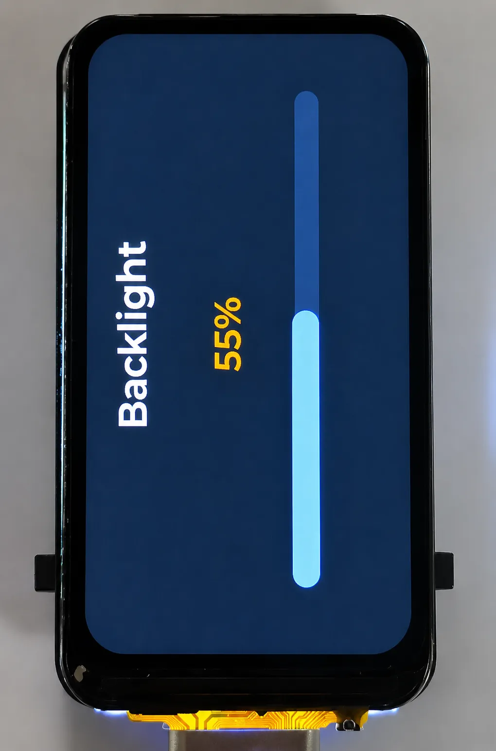
Example Description
- This example uses LEDC PWM to adjust the LCD backlight brightness.
- The LVGL page simultaneously displays the current brightness percentage and a progress bar.
Hardware Connection
- Connect the development board to the computer.
- This example uses only the onboard LCD and backlight; no external modules are required.
Code Analysis
setup(): Initializes the LCD, LVGL, and the backlight example UI.init_display(): Starts the LCD and sets the initial backlight.init_lvgl(): Configures the LVGL display buffer and refresh callback.create_ui(): Creates a brightness value label and a progress bar.loop(): Periodically callsset_backlight()andupdate_ui()to vary the backlight brightness as a percentage.lvgl_loop_once(): Advances the LVGL tick and handles UI refresh.
Running Effect
- The LCD backlight brightness cycles, and the percentage and progress bar on the screen update synchronously.
04_ws2812_rgb
Example Description
- This example uses
rgbLedWrite()from the ESP32 Arduino core to control the onboard WS2812B RGB LED. - The LED cycles through colors such as red, green, blue, etc.
Hardware Connection
- Connect the development board to the computer.
- This example uses only the onboard RGB LED; no external modules are required.
Code Analysis
setup(): Initializes serial and prints the example name.set_led(): Wraps the RGB LED color setting. For the onboard LED, the parameter order isred, green, blue.loop(): Callsset_led()at fixed intervals to cycle the RGB LED through different colors.
Running Effect
- The onboard WS2812B RGB LED switches colors in sequence.
05_sdcard_rw
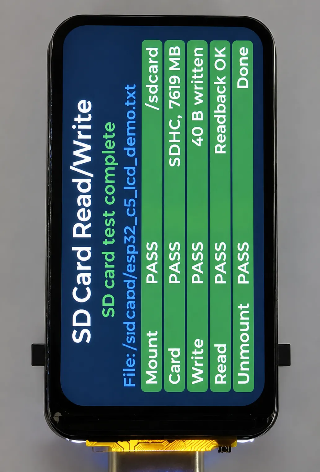
Example Description
- This example mounts a TF card via SDSPI and performs file write and read-back verification.
- The LCD page shows the TF card mount, write, read, and result statuses.
Hardware Connection
- Connect the development board to the computer.
- Insert a FAT or FAT32-formatted TF card into the board.
Code Analysis
setup(): Initializes the LCD, LVGL, TF card pins, and status UI, then performs the TF card read/write test.init_sd_pins(): Configures the TF card related pin states.mount_sd_card(): Mounts the TF card via SDSPI and reads card type and capacity.write_file(): Writes a test file to the TF card.read_file(): Reads back the test file content and verifies data consistency.set_item()andset_summary(): Update the step status and final result on the LCD.loop(): Callslvgl_loop_once()to keep the UI refreshed.
Running Effect
- The LCD displays the TF card capacity, file write/read results, and the serial outputs detection information simultaneously.
06_spiffs_rw
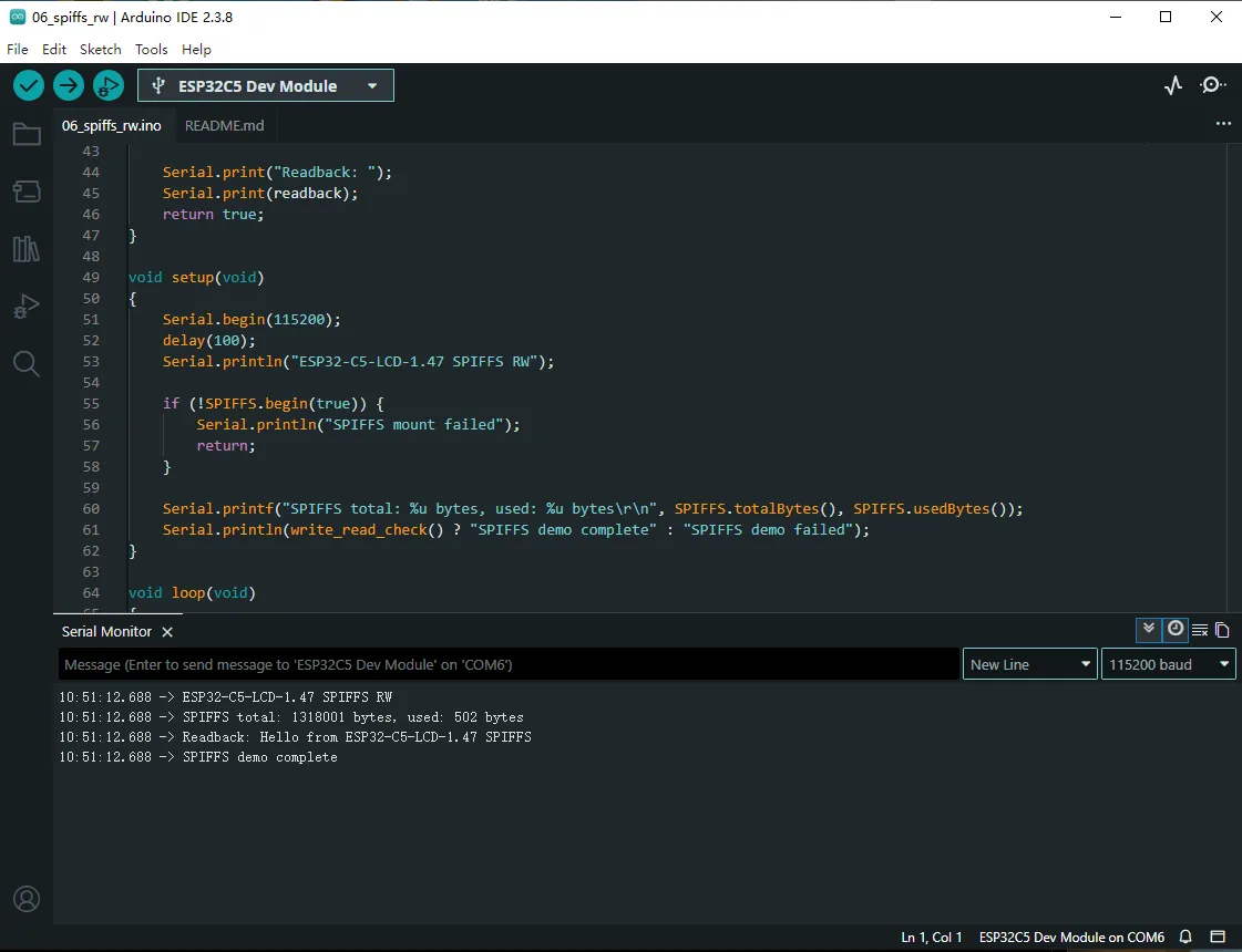
Example Description
- This example mounts the SPIFFS file system in internal Flash.
- The program writes
/hello.txt, reads it back, and outputs the content via serial.
Hardware Connection
- Connect the development board to the computer.
- Before compiling and flashing, select a partition scheme that includes SPIFFS.
Code Analysis
setup(): Initializes serial, mounts SPIFFS withSPIFFS.begin(true), and prints total and used capacity.write_read_check(): Deletes the old test file, writes new content, reads it back, and checks if the string matches.loop(): This example has no loop task.
Running Effect
- The serial outputs SPIFFS capacity information, the read-back content, and the test completion status.
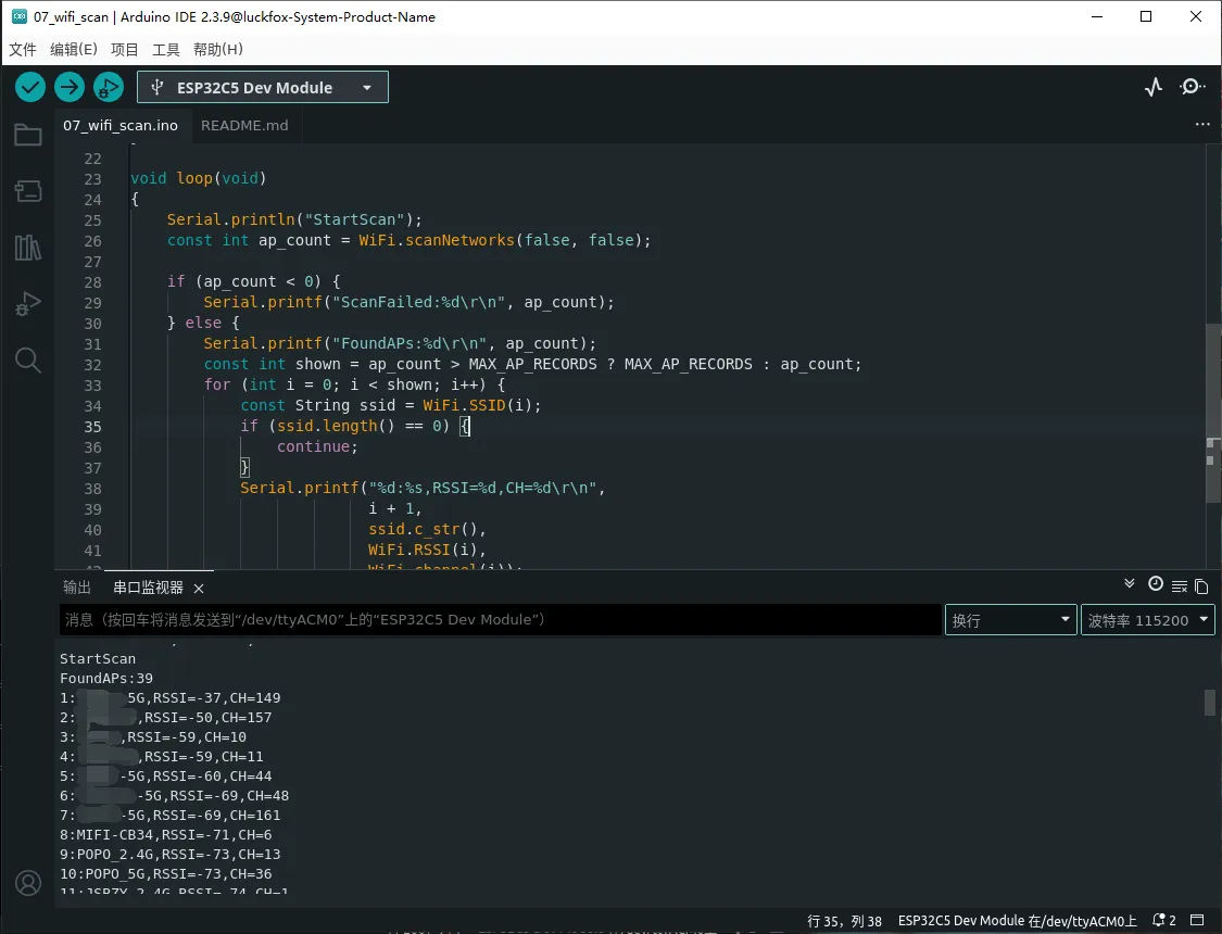
07_wifi_scan
Example Description
- This example uses the ESP32-C5 built-in Wi-Fi to scan for nearby networks.
- The serial outputs the SSID, RSSI, and channel information of discovered networks.
Hardware Connection
- Connect the development board to the computer.
- Ensure there are 2.4 GHz or 5 GHz Wi-Fi networks within range.
Code Analysis
setup(): Initializes serial, sets Wi-Fi to STA mode, and disconnects any existing connection.loop(): CallsWiFi.scanNetworks()to scan, then outputs the number of networks, SSID, RSSI, and channel for each.WiFi.scanDelete(): Frees the resources used by the scan results.
Running Effect
- The serial outputs Wi-Fi scan results approximately every 5 seconds.
08_board_showcase
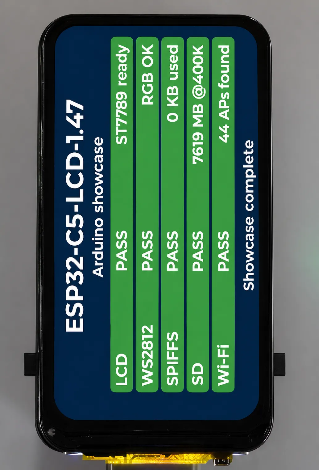
Example Description
- This example comprehensively tests the LCD, backlight, WS2812B RGB LED, SPIFFS, TF card, and Wi-Fi scanning.
- The LCD page shows the status of each feature as
RUN,PASS,WARNorFAIL.
Hardware Connection
- Connect the development board to the computer.
- If you want to test the TF card, insert a FAT or FAT32-formatted TF card into the board.
- Before compiling and flashing, select a partition scheme that includes SPIFFS.
Code Analysis
setup(): Initializes the LCD, LVGL, status UI, and the comprehensive test flow.create_ui(): Creates the board resource status panel.run_showcase(): Sequentially checks the LCD, RGB LED, SPIFFS, TF card, and Wi-Fi.file_rw_check(): Performs file write and read-back verification on SPIFFS or the TF card.mount_sd_card(): Mounts the TF card and reads capacity information.set_item(): Updates the status and description text for each feature.loop(): Callslvgl_loop_once()to keep the UI refreshed.
Running Effect
- The LCD shows the test result for each feature; after completion, the final status is displayed at the bottom. If no TF card is inserted or no Wi-Fi is scanned, the corresponding items show a warning.
Usage Notes
- Before running
05_sdcard_rw, insert a FAT or FAT32-formatted TF card. 06_spiffs_rwand08_board_showcaserequire a partition scheme that includes SPIFFS.- The LCD and TF share SPI clock and MOSI pins; the examples are already configured for the onboard connections.
- The onboard RGB LED examples pass color parameters in the order
red, green, blue.
Working with ESP-IDF
When using the device, keep the screen brightness below 50% and avoid running it at full brightness for extended periods. Excessive brightness will raise the screen temperature and may cause dark shadows to appear on the display.
If display issues occur, power off the board and let it rest for a while before flashing a program with lower brightness settings.
This chapter contains the following sections. Please read as needed:
ESP-IDF Getting Started
New to ESP32 ESP-IDF development and looking to get started quickly? We have prepared a general Getting Started Tutorial for you.
- Section 1: Environment Setup
- Section 2: Running Examples
- Section 3: Creating a Project
- Section 4: Using Components
- Section 5: Debugging
- Section 6: FreeRTOS
- Section 7: Peripherals
- Section 8: Wi-Fi Programming
- Section 9: BLE Programming
Please Note: This tutorial uses the ESP32-S3-Zero as a teaching example, and all hardware code is based on its pinout. Before you start, it is recommended that you check the pinout of your development board to ensure the pin configuration is correct.
Setting Up the Development Environment
Please refer to Install ESP-IDF Development Environment.
The ESP32-C5-LCD-1.47 examples require ESP-IDF v5.3.0 or newer.
The following guide uses Windows as an example, demonstrating development using VS Code + the ESP-IDF extension. macOS and Linux users should refer to the official documentation.
The screenshots in this section use ESP-IDF V5.5.2 as an example. When installing, please select the ESP-IDF version that matches your board's example.
Install the ESP-IDF Development Environment
Download the installation manager from the ESP-IDF Installation Manager page. This is Espressif's latest cross-platform installer. The following steps demonstrate how to use its offline installation feature.
Click the Offline Installer tab on the page, then select Windows as the operating system and the ESP-IDF version you need (the version shown in the screenshot is for reference only — choose the version that fits your actual needs).
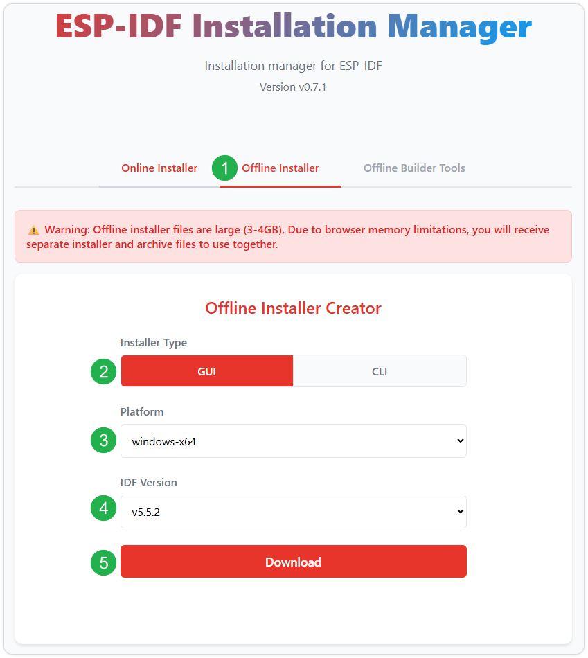
After confirming your selection, click the download button. The browser will automatically download two files: the ESP-IDF Offline Package (.zst) and the ESP-IDF Installer (.exe).
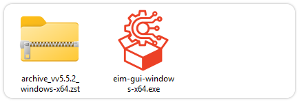
Please wait for both files to finish downloading.
Once the download is complete, double-click to run the ESP-IDF Installer (eim-gui-windows-x64.exe).
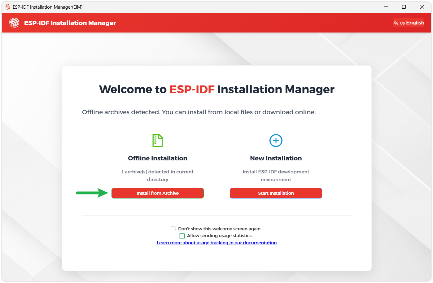
The installer will automatically detect if the offline package exists in the same directory. Click Install from archive.
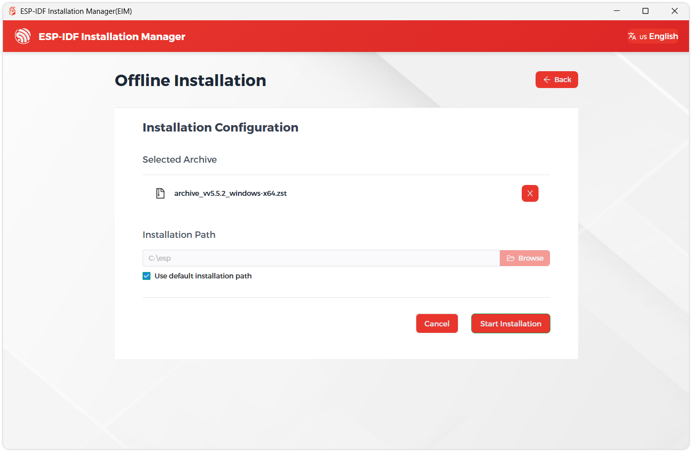
Next, select the installation path. We recommend using the default path. If you need to customize it, ensure the path does not contain Chinese characters or spaces. Click Start installation to proceed.
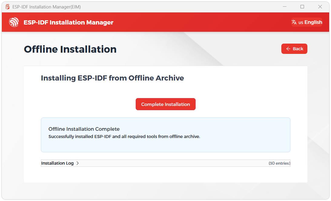
When you see the following screen, the ESP-IDF installation is successful.
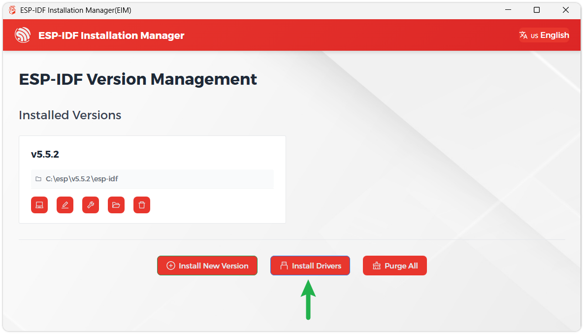
We recommend installing the drivers as well. Click Finish installation, then select Install driver.
Install Visual Studio Code and the ESP-IDF Extension
Download and install Visual Studio Code.
During installation, it is recommended to check Add "Open with Code" action to Windows Explorer file context menu to facilitate opening project folders quickly.
In VS Code, click the Extensions icon
 in the Activity Bar on the side (or use the shortcut Ctrl + Shift + X) to open the Extensions view.
Enter ESP-IDF in the search box, locate the ESP-IDF extension, and click Install.
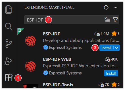
For ESP-IDF extension versions ≥ 2.0, the extension will automatically detect and recognize the ESP-IDF environment installed in the previous steps, requiring no manual configuration.
Example
The example programs are located in the examples/esp-idf directory of the resource package. Each example's sdkconfig.defaults already specifies the target chip as esp32c5, so you generally do not need to run idf.py set-target esp32c5 again.
Building and Flashing
Navigate to any ESP-IDF example directory and run:
cd esp-idf/02_lvgl_hello
idf.py build flash monitor
If you need to specify a serial port, replace COMx with the actual port, for example COM5:
idf.py -p COMx build flash monitor
Example List
| Example Directory | Description |
|---|---|
01_lcd_panel_basic | Initialize the LCD without LVGL, draw color bars and a moving color block |
02_lvgl_hello | Start the BSP LVGL display interface and show a basic UI |
03_backlight_fade | Adjust the LCD backlight brightness and display the brightness changes on screen |
04_ws2812_rgb | Control the onboard WS2812B RGB LED to cycle through different colors |
05_sdcard_rw | Mount a TF card and perform file write and read-back verification |
06_spiffs_rw | Mount the SPIFFS partition in internal Flash and perform file write and read-back verification |
07_wifi_scan | Scan nearby Wi-Fi networks and output the scan results via serial |
08_board_showcase | Comprehensive demonstration of LCD, backlight, RGB LED, SPIFFS, TF card, and Wi-Fi status |
01_lcd_panel_basic
Example Description
- This example initializes the ST7789 LCD via the BSP without starting LVGL.
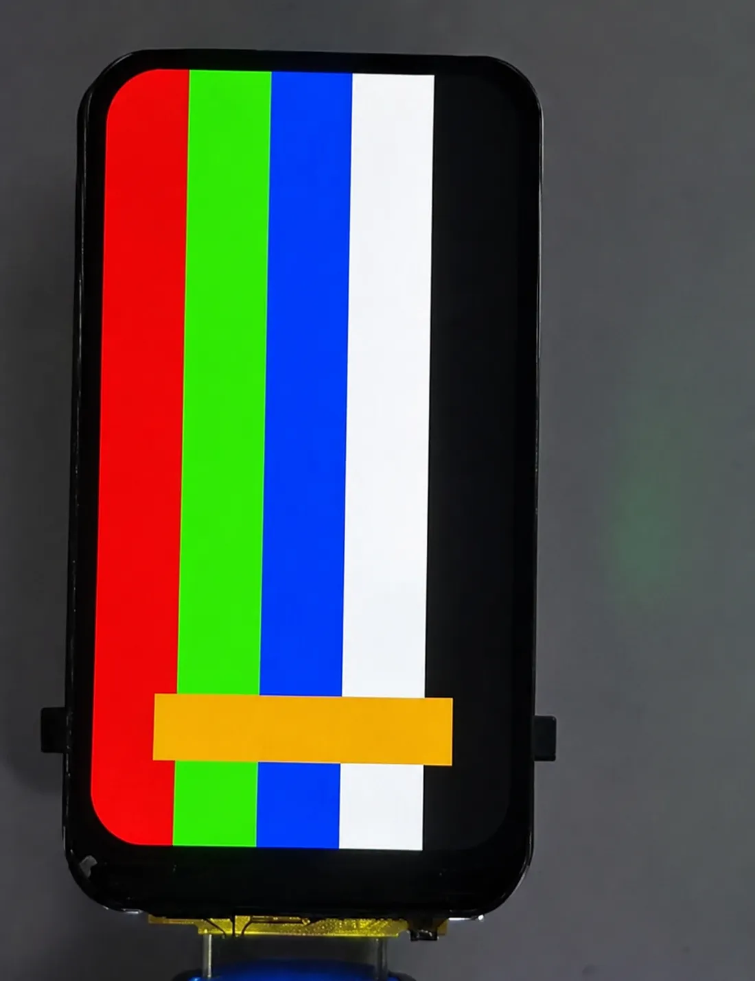
- The LCD first displays a multi-color stripe background, then shows a moving color block to check display and partial refresh functionality.
Hardware Connection
- Connect the development board to the computer.
- This example uses only the onboard LCD and backlight; no external modules are required.
Code Analysis
app_main(): Creates the LCD panel, initializes backlight, registers the transfer-complete callback, and starts the display flow.bsp_display_new(): Creates the LCD panel and panel IO objects.bsp_display_brightness_init()andbsp_display_brightness_set(): Initialize and set the LCD backlight.draw_color_bars(): Draws a multi-color stripe background in blocks.esp_lcd_panel_draw_bitmap(): Writes image data to the specified LCD region.draw_moving_bar_region(): Refreshes the moving color block and the background area it covers.
Running Effect
- The LCD displays a multi-color stripe background with a color block moving up and down continuously.
02_lvgl_hello
Example Description
- This example starts the BSP LVGL display interface and draws a basic UI on the LCD.
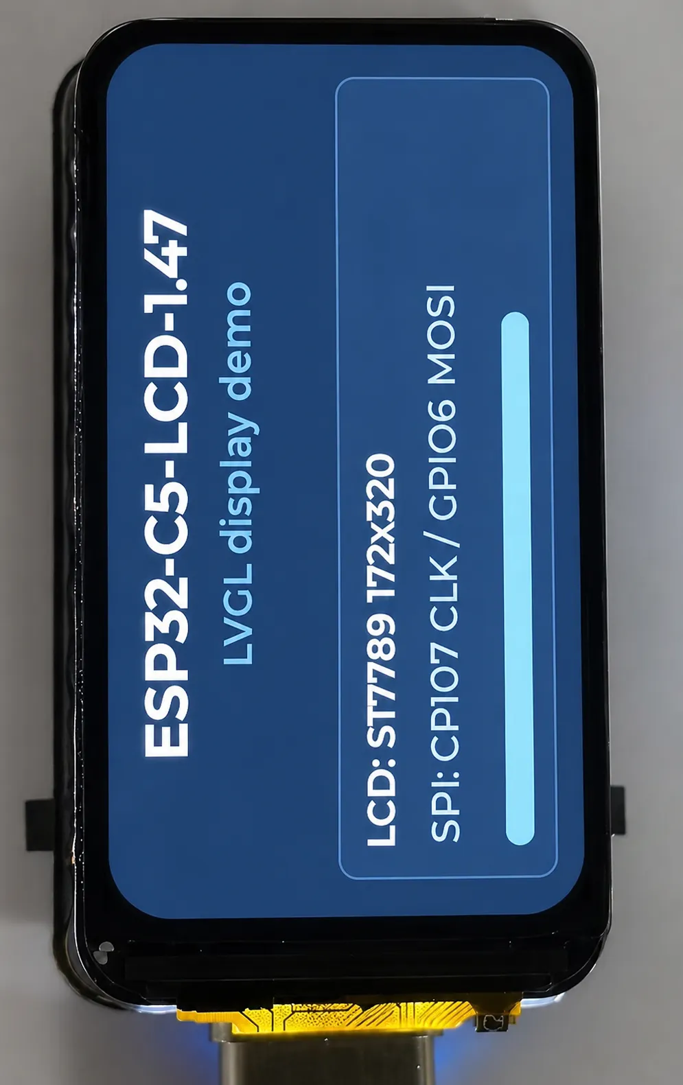
- The screen shows the board name, LCD resolution, SPI pin information, and a status bar.
Hardware Connection
- Connect the development board to the computer.
- This example uses only the onboard LCD and backlight; no external modules are required.
Code Analysis
app_main(): Starts the BSP display service, sets screen orientation and backlight, and creates the LVGL UI.bsp_display_start(): Starts the LCD panel and LVGL port.bsp_display_rotate(): Sets the screen rotation.bsp_display_backlight_on(): Turns on the LCD backlight.bsp_display_lock()andbsp_display_unlock(): Protect the LVGL UI creation process.create_ui(): Creates the title, description text, device info, and status bar.
Running Effect
- The LCD shows the LVGL example interface, including the board name, LCD parameters, and SPI pin information.
03_backlight_fade
Example Description
- This example uses
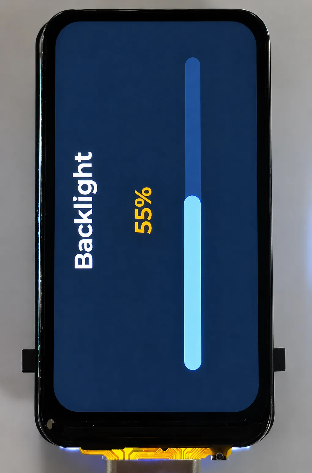
bsp_display_brightness_set()to adjust the LCD backlight brightness. - The LVGL page simultaneously displays the current brightness percentage and a progress bar.
Hardware Connection
- Connect the development board to the computer.
- This example uses only the onboard LCD and backlight; no external modules are required.
Code Analysis
app_main(): Starts the BSP display service, creates the brightness UI, and enters the brightness loop.create_ui(): Creates the brightness title, percentage label, and progress bar.bsp_display_brightness_set(): Sets the LCD backlight according to the current percentage.update_ui(): Updates the LVGL label and progress bar values.bsp_display_lock()andbsp_display_unlock(): Protect the LVGL widget update process.
Running Effect
- The LCD backlight brightness cycles, and the percentage and progress bar on the screen update synchronously.
04_ws2812_rgb
Example Description
- This example initializes the onboard WS2812B RGB LED and cycles through different colors.
- This example is mainly used to verify the onboard RGB LED control functionality.
Hardware Connection
- Connect the development board to the computer.
- This example uses only the onboard RGB LED; no external modules are required.
Code Analysis
app_main(): Initializes the RGB LED and enters the color loop.bsp_ws2812b_init(): Initializes the onboard WS2812B LED.bsp_setledcolor(): Sets the red, green, and blue brightness for the specified LED.vTaskDelay(): Controls the color switching interval.
Running Effect
- The onboard WS2812B RGB LED switches colors in sequence.
05_sdcard_rw
Example Description
- This example mounts a TF card via SDSPI and performs file write and read-back verification.
- The LCD page shows the TF card mount, write, read, and result statuses.
Hardware Connection
- Connect the development board to the computer.
- Insert a FAT or FAT32-formatted TF card into the board.
Code Analysis
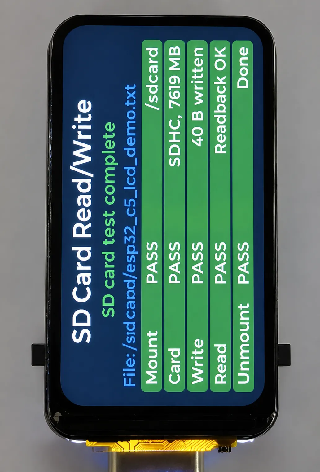
app_main(): Starts the LCD and LVGL UI, mounts the TF card, and performs the read/write test.bsp_sdcard_mount(): Mounts the TF card.sd_write_file(): Writes a test file to the TF card.sd_read_file(): Reads back the test file content and verifies data consistency.set_item()andset_summary(): Update the step status and final result on the LCD.bsp_sdcard_unmount(): Unmounts the TF card after the test completes.
Running Effect
- The LCD displays the TF card capacity, file write/read results, and the serial outputs detection information simultaneously.
06_spiffs_rw
Example Description
- This example mounts the SPIFFS partition named
storage. - The program writes a test file, reads it back, and outputs the content via serial.
Hardware Connection
- Connect the development board to the computer.
- This example uses a custom partition table in the project and does not require external modules.
Code Analysis
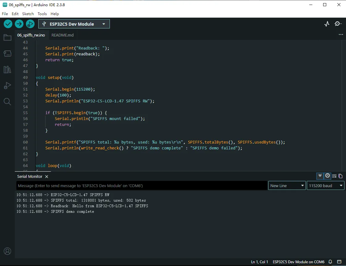
app_main(): Mounts SPIFFS, writes a test file, reads it back, and outputs the verification result.bsp_spiffs_mount(): Mounts thestorageSPIFFS partition.fopen(),fwrite()andfread(): Perform file write and read-back operations.bsp_spiffs_unmount(): Unmounts SPIFFS after the test completes.
Running Effect
- The serial outputs SPIFFS mount status, file read/write results, and the test completion status.
07_wifi_scan
Example Description
- This example uses the ESP32-C5 built-in Wi-Fi to scan for nearby networks.
- The serial outputs information such as SSID, RSSI, channel, and authentication mode.
Hardware Connection
- Connect the development board to the computer.
- Ensure there are 2.4 GHz or 5 GHz Wi-Fi networks within range.
Code Analysis
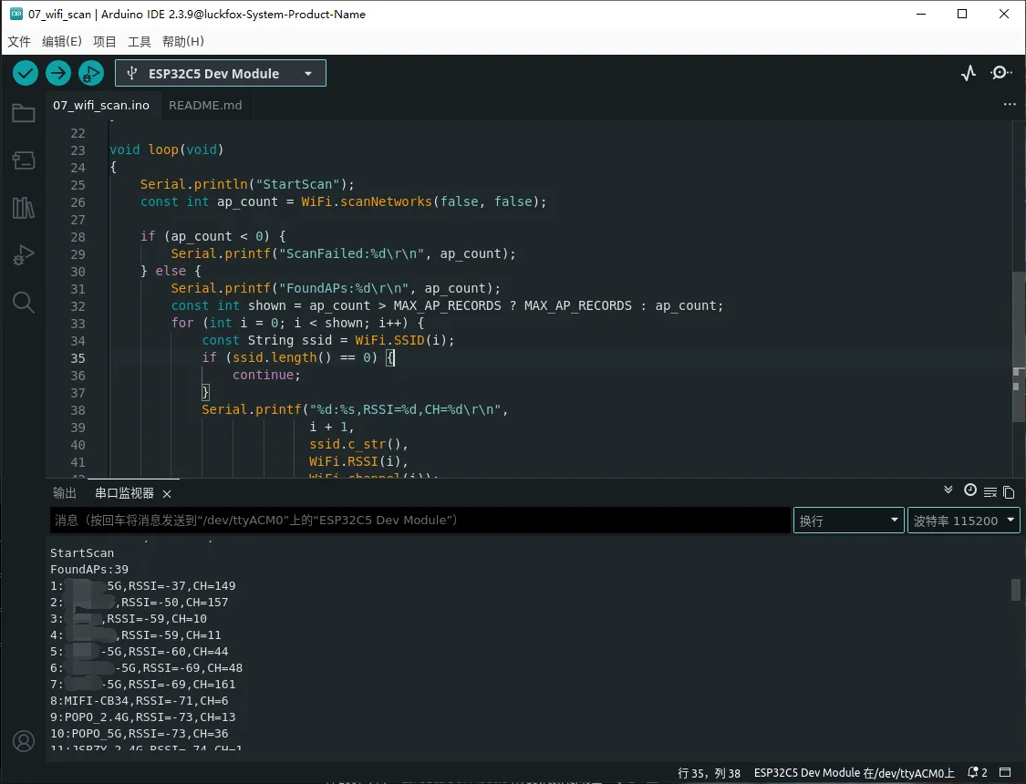
app_main(): Initializes NVS and Wi-Fi STA mode, and creates a scan task.init_nvs(): Initializes NVS for use by the Wi-Fi component.init_wifi_sta(): Initializes Wi-Fi and sets it to STA mode.wifi_scan_task(): Periodically performs Wi-Fi scans and outputs the results.ssid_to_printable_ascii(): Filters non-printable characters for proper SSID display over serial.
Running Effect
- The serial periodically outputs Wi-Fi scan results, including the number of networks, SSID, RSSI, and channel information.
08_board_showcase
Example Description
- This example comprehensively tests the LCD, backlight, WS2812B RGB LED, SPIFFS, TF card, and Wi-Fi scanning.
- The LCD page shows the status of each feature as
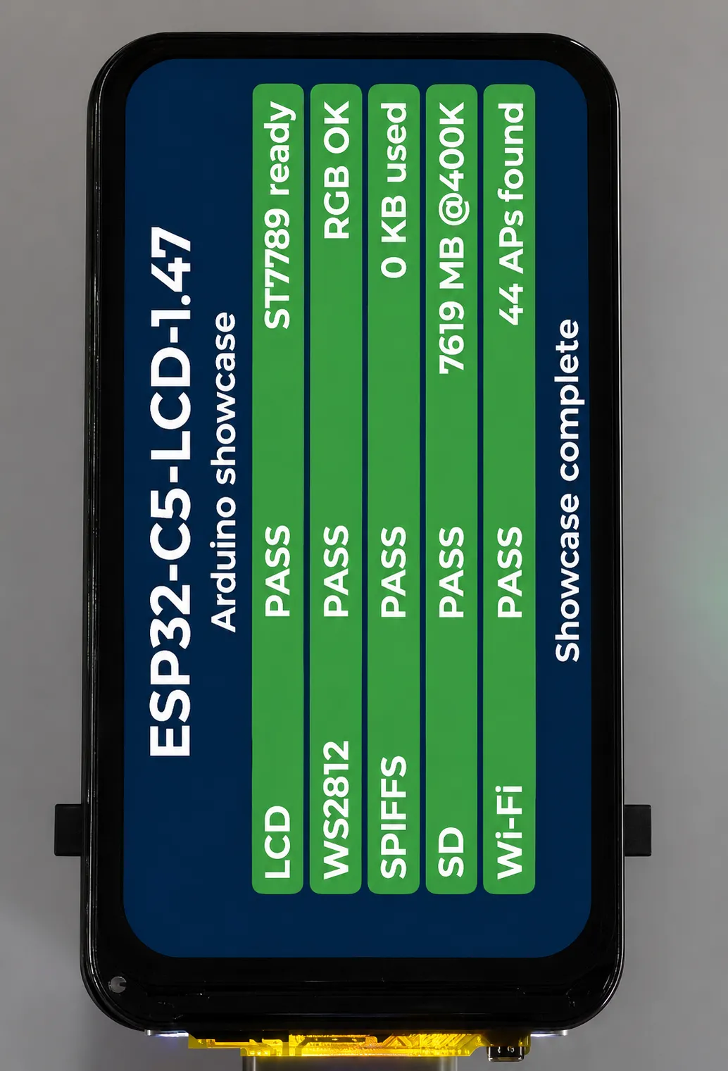
RUN,PASS,WARNorFAIL. - The RGB LED changes color according to the final test result.
Hardware Connection
- Connect the development board to the computer.
- If you want to test the TF card, insert a FAT or FAT32-formatted TF card into the board.
Code Analysis
app_main(): Starts the BSP display service, sets screen orientation and backlight, and creates the comprehensive test task.create_ui(): Creates the board resource status panel.showcase_task(): Sequentially checks the LCD, RGB LED, SPIFFS, TF card, and Wi-Fi.write_read_file(): Performs file write and read-back verification on SPIFFS or the TF card.wifi_scan_once(): Performs a single Wi-Fi scan and generates a status text.set_item(): Updates the status and description text for each feature.bsp_setledcolor(): Sets the RGB LED color according to the final status.
Running Effect
- The LCD shows the test result for each feature; after completion, the final status is displayed at the bottom, and the RGB LED simultaneously shows the final status color.
Board Showcase Status Description
08_board_showcase displays the test result for each feature on the LCD, and uses the RGB LED to indicate the overall status.
| LED State | Meaning |
|---|---|
| Green | All items are PASS. |
| Yellow | There is a WARN, such as no TF card inserted or no Wi-Fi networks found. |
| Red | There is a FAIL, indicating a feature test has failed. |
Instructions:
- If no TF card is inserted, the TF item shows
CHECKorNo card, and the final LED state is yellow. - If no Wi-Fi networks are found, the Wi-Fi item shows a warning, and the final LED state is yellow.
- SPIFFS may prompt for formatting on first run; this is normal.
Usage Notes
- Before running
05_sdcard_rw, insert a FAT or FAT32-formatted TF card. 06_spiffs_rwand08_board_showcaseuse a custom partition table that includes thestorageSPIFFS partition.- The LCD and TF share SPI clock and MOSI pins, with the SPI bus initialized by the BSP.
- The onboard RGB LED examples pass color parameters in the order
red, green, blue. - The current BSP does not support touch, buttons, audio, or IMU functions.
Resources
1. Hardware Resources
- Development Board Design File
Technical Manuals
ESP32-C5 Chip Official Manuals
LCD Manuals
WS2812 Manuals
Software Development Resources
Example
Debugging Tools
Support
Monday-Friday (9:30-6:30) Saturday (9:30-5:30)
Email: services01@spotpear.com
[Tutorial Navigation]
- Overview
- Features
- Onboard Resources
- Interface Overview
- Product Dimensions
- Product Specifications
- Working with Arduino
- Arduino Getting Started
- Setting Up the Development Environment
- 1. Installing and Configuring the Arduino IDE
- 2. Installing the ESP32 Development Board
- 3. Installing the Libraries
- Example
- Working with ESP-IDF
- ESP-IDF Getting Started
- Setting Up the Development Environment
- Example
- Resources
- Support