- sales/support
Google Chat:---
- sales
+86-0755-88291180
- sales01
sales@spotpear.com
- sales02
dragon_manager@163.com
- support
tech-support@spotpear.com
- CEO-Complaints
zhoujie@spotpear.com
- Only Tech-Support
WhatsApp:13246739196
- Purchase/Shipping/Refund
WhatsApp:13424403025
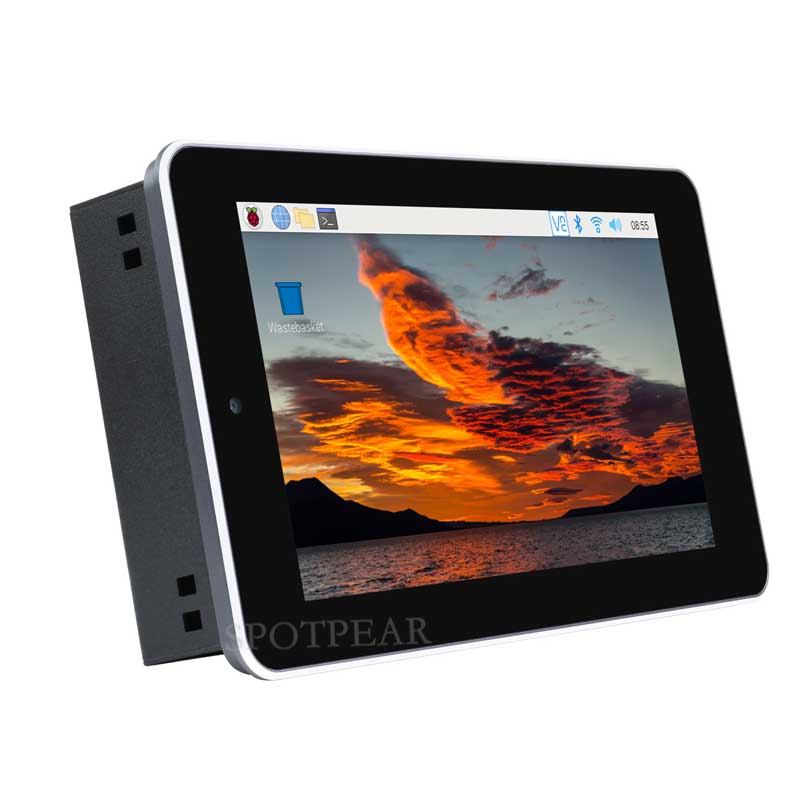
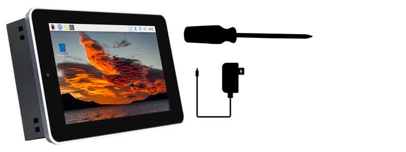
Raspberry Pi CM4 Kit 7-inch Touch Screen All-in-one Kit 5-megapixel Camera Aluminum Alloy Case
$141.9
Brand:SpotPear
SKU:01053800000
Date:2025-06-10 14:33
Part Number:
Raspberry Pi CM4 Kit 7-inch Touch Screen All-in-one Kit 5-megapixel Camera Aluminum Alloy Case
7″ Touch Screen All-In-One Kit
Designed for Raspberry Pi Compute Module 4
This product does not contain the Compute Module 4 core board
Specifications
| CM4 SOCKET | suitable for all variants of Compute Module 4 |
|---|---|
| NETWORKING | Gigabit Ethernet RJ45 |
| M.2 M KEY, supports NVME SSD | |
| USB | USB 2.0 × 4 |
| CONNECTOR | isolated RS485, RS232, GPIO, and I2C |
| DISPLAY | 7inch, 800 × 480 pixels, 5-points capacitive touch, toughened glass panel |
| CAMERA | 5MP, F2.4, 3.89mm fixed focal length, supports video recording |
| VIDEO | HDMI, supports 4K 30fps output |
| RTC | Real-time clock with battery socket and ability to wake Compute Module 4 |
| STORAGE | MicroSD card socket for Compute Module 4 Lite (without eMMC) variants |
| FAN | 5V/12V, allows speed adjustment and measurement |
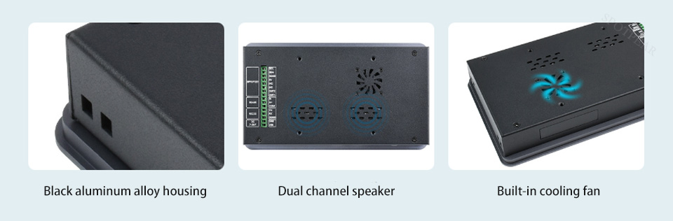
| SPEAKER | 8Ω 2W dual track speakers |
| POWER INPUT | 7-36V |
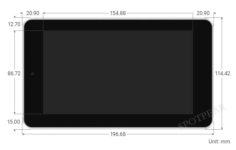
| DIMENSIONS | 196.68 × 114.42mm |
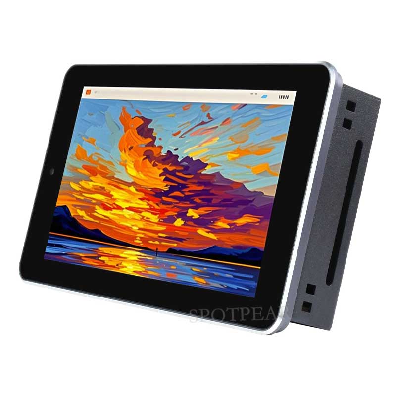
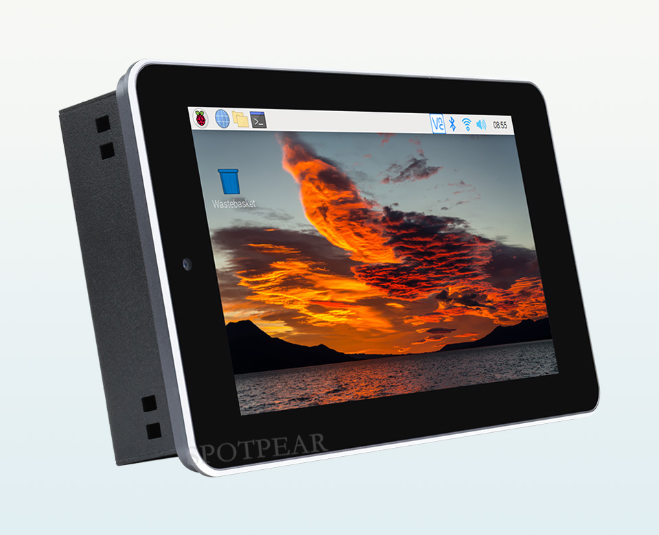
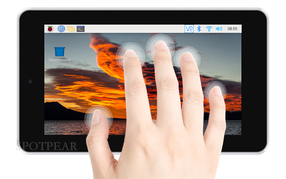
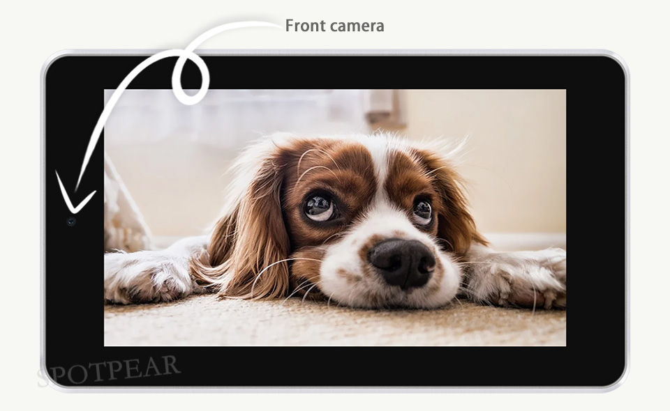
Toughened Glass Screen
7inch Capacitive Touch Screen, 5-Points Capacitive Touch
Along With Toughened Glass Panel, More Safe To Use
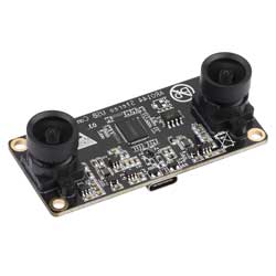
5MP Front Camera
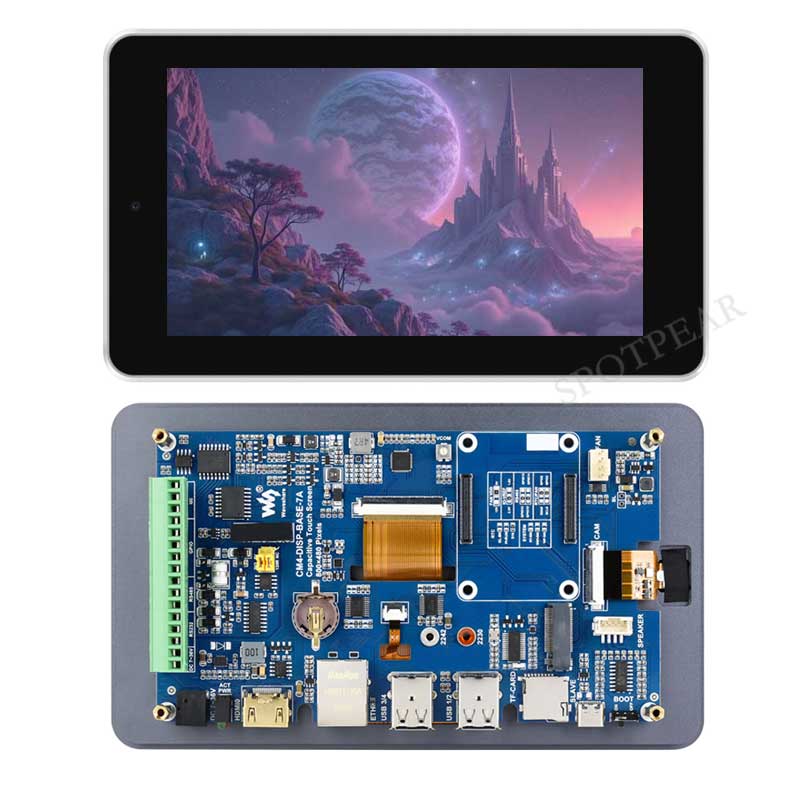
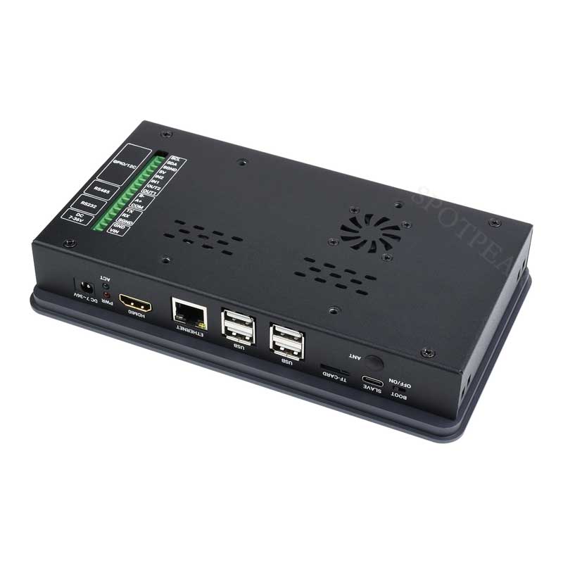
Design Details
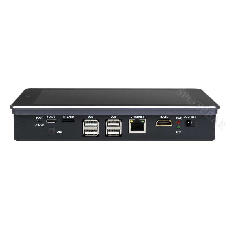
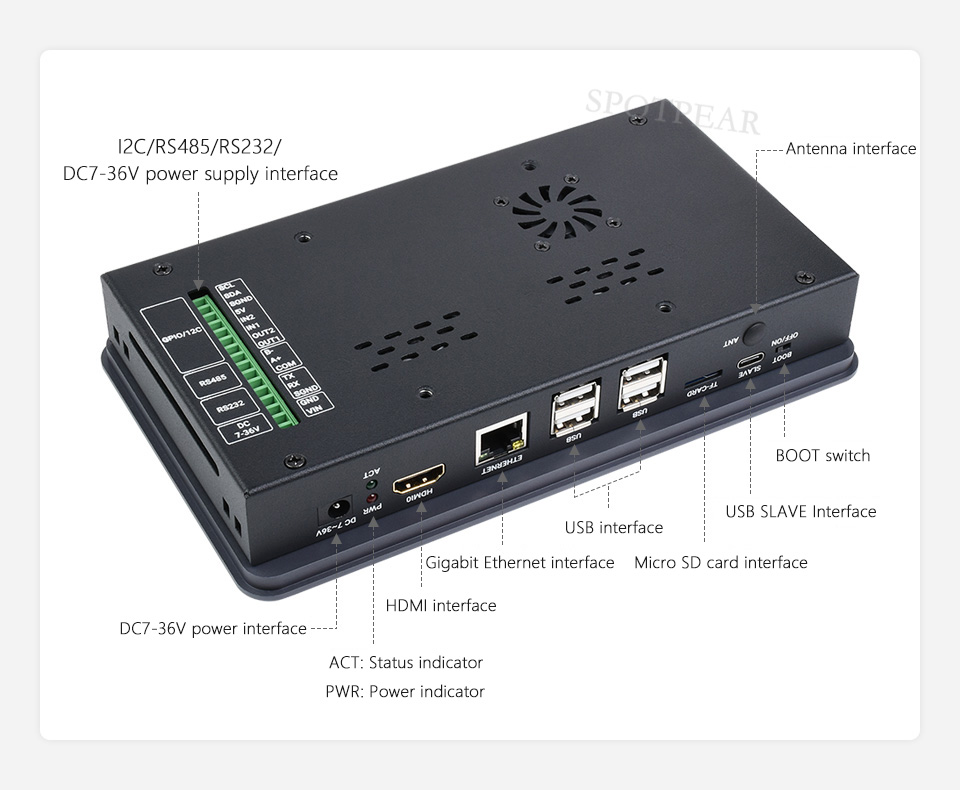
Rich Interfaces
Providing Interfaces Including: CSI, HDMI, USB, M.2, ETH, RS232, RS485
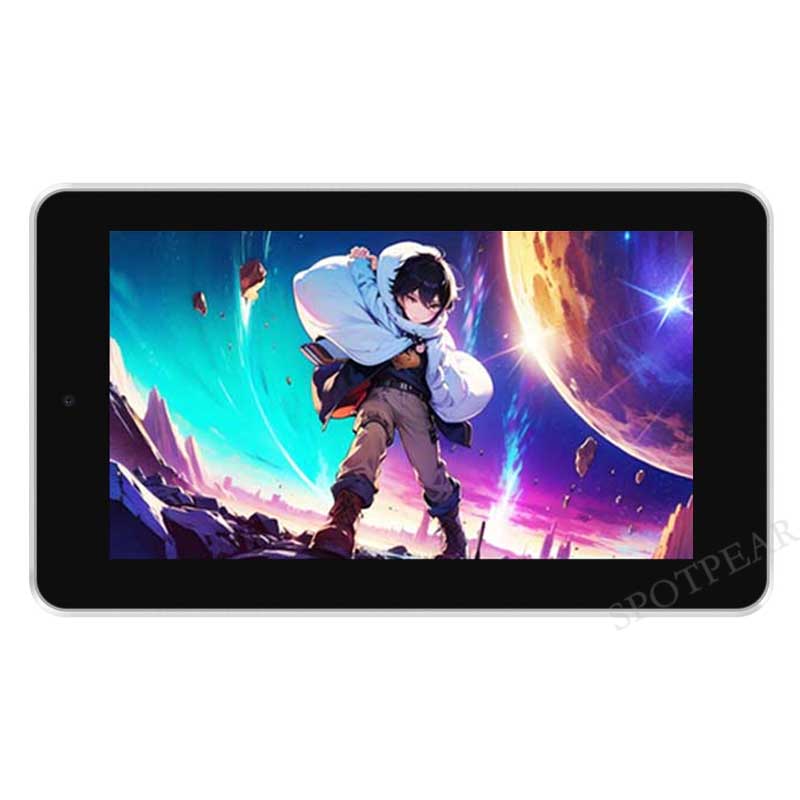
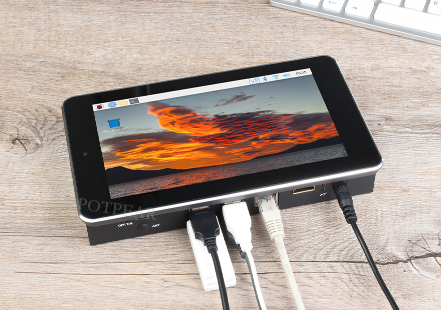
Application Example
Suitable For Raspberry Pi Projects Where Multi Peripherals Are Required,
Or Other Industrial Applications
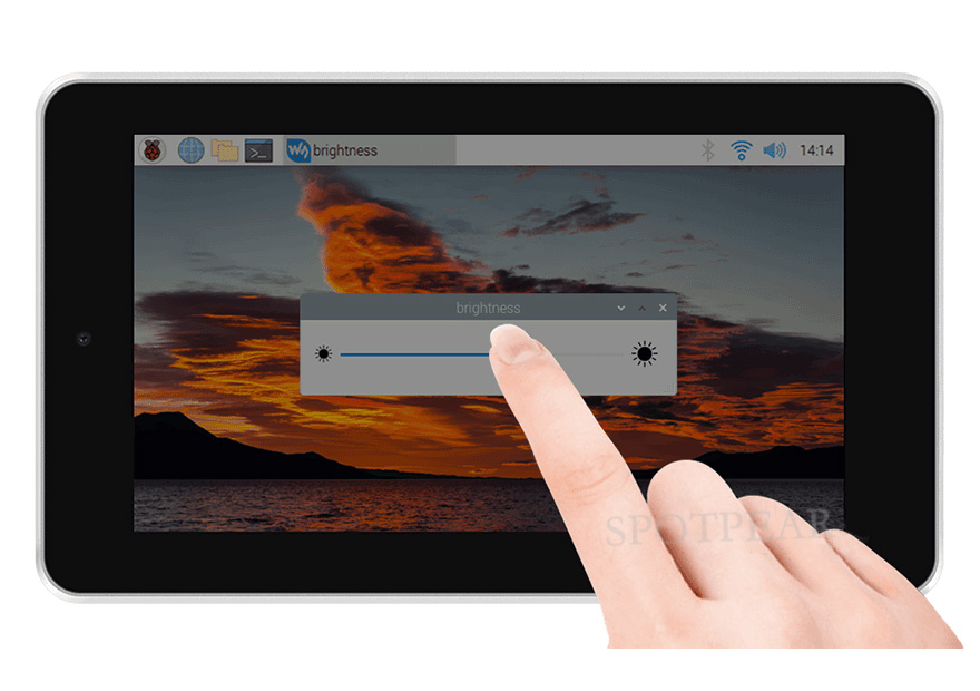
Adjustable Brightness Via Software
What's On Board
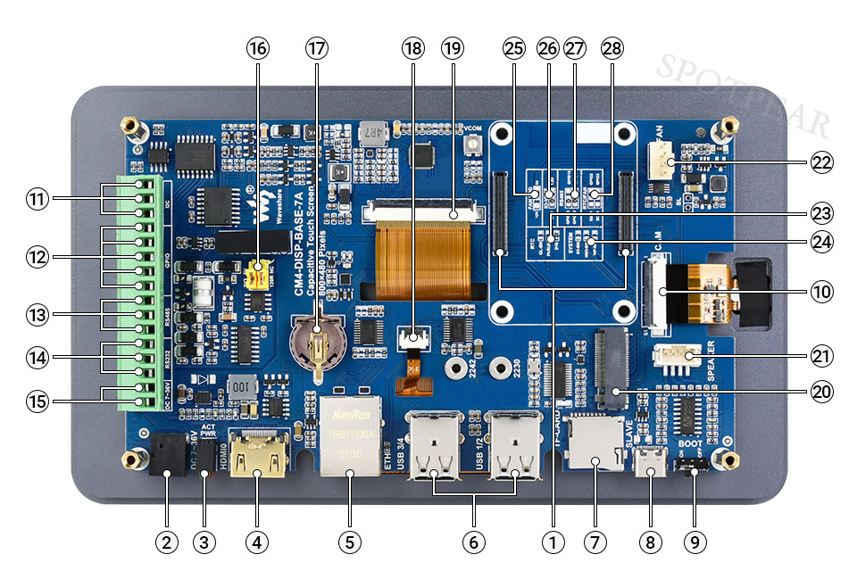
- CM4 socket
suitable for all variants of Compute Module 4 - DC power supply
7 ~ 36V DC input - CM4 status indicator
PWR: Raspberry Pi power indicator
ACT: Raspberry Pi operating status indicator - HDMI connector
supports 4K 30fps output - RJ45 Gigabit Ethernet
10/100/1000M compatible - USB 2.0 ports
4x USB 2.0, for connecting sorts of USB devices - Micro SD card slot
for connecting a Micro SD card with pre-burnt image (Lite variant ONLY) - USB SLAVE port
USB programming port - BOOT selection
ON: CM4 will be booted from USB-C interface
OFF: CM4 will be booted from eMMC or Micro SD card - MIPI CSI connector
connected to the 5MP front camera - Isolated I2C
for controlling or reading data from devices via I2C - Isolated GPIO
for controlling or detecting devices via GPIO - Isolated RS485
- Isolated RS232
- DC power supply
7 ~ 36V DC input - RS485 terminal resistor and GPIO logic level selection
RS485: connect/disconnect the 120R resistor
GPIO: GPIO logic level selection
- RTC battery holder
supports CR1220 button cell - Touch screen header
connected to the capacitive touch screen - Display connector
connected to the 7inch 800×480 display - M.2 M KEY
supports M.2 M KEY NVME SSD, or other communication modules using PCIe channel - Speaker header
audio output - FAN header
for connecting cooling fan, allows speed adjustment and measurement - RTC interruption configuration
GL-EN: CM4 powerdown on RTC interruption
PI-RUN: CM4 will reboot on RTC interruption
D16: D16 pin is triggered on RTC interruption (default) - System function configuration
BT_DIS: Bluetooth disabled, for CM4 with antenna variant ONLY
WiFi_DIS: WiFi disabled, for CM4 with antenna variant ONLY
WP_DIS: boot mode switch, ONLY be used when NOT booted from eMMC or SD card - FAN power supply selection
select 5V (default) or 12V power to drive the fan - IO-VREF selection
set the CM4 IO logic level as 3.3V (default) or 1.8V - RS485 switch
GPIO13/12: using ttyAMA1 device (default)
GPIO15/14: using ttyS0 device - RTC/FAN I2C bus selection
SDA0/SCL0: I2C-10 is shared with CSI/DSI
GPIO3/2: I2C-1 is shared with 40PIN GPIO (default)
Outline Dimensions
TAG:
Raspberry Pi screen
Attitude Sensor
PC USB Monitor Screen
2.42 inch 128×64
Jetson Xavier NX AI 21TOPS Supercomputer Edge Computing eMMC-16GB RAM 8GB 16GB NVIDIA
ESP32-S3 ST7789
Raspberry Pi PICO Long-Range Communication
2.8inch Round LCD
Raspberry Pi 5 Gigabit PoE Switch 120W High Speed 10-100-1000Mbps RJ45 PoE
PC USB Monitor Screen
SpotPear
Raspberry Pi USB Camera 8MP IMX415 Distortion-Free Dual Microphones USB 2.0 For Jeston RDK
ESP32-S3
Jetson Orin 5G/4G/3G expansion board GNSS GPS RM520N-GL
Raspberry Pi Pico
Industrial USB TO RS485 Isolated Bidirectional Converter Original (E) FT232RNL 1200m Long Distance
voice module
1.69inch LCD TouchScreen Display 240×280 ST7789 Arduino Raspberry Pi ESP32S3 Pico STM32
Pi5
ESP32-S3 1.28inch Round LCD
Forum: