- sales/support
Google Chat:---
- sales
+86-0755-88291180
- sales01
sales@spotpear.com
- sales02
dragon_manager@163.com
- support
tech-support@spotpear.com
- CEO-Complaints
zhoujie@spotpear.com
- Only Tech-Support
WhatsApp:13246739196
- Purchase/Shipping/Refund
WhatsApp:13424403025
- HOME
- >
- ARTICLES
- >
- Common Moudle
- >
- LCD
LCD1602 I2C Module User Guide
Features
- I2C interface, only two cables can be directly controlled, easy to access a variety of control boards
- Can display up to 16 x 2 characters, support screen scrolling, cursor movement, and other functions
- The appearance is exquisite and compact, and the workmanship is exquisite and beautiful. Highly integrated design, stable performance, fine workmanship, compact body with the dimensions of 87 * 32 * 13 mm.
- Onboard AiP31068L LCD driver chip
- Provide complete supporting information manuals (user manuals/sample demos)
Parameters
- Operating voltage: 3.3V/5V
- Communication interface: I2C
- Screen type: LCD screen
- Control chip: AiP31068L
- Display dimensions: 64.5 x 16.0 mm
- Outline dimensions: 87.0 x 32.0 x 13.0(mm)
- Operating current: 26mA(5V), 13mA (3.3V)
Interface Description
| Pin | Description |
| VCC | 3.3V/5V power input |
| GND | Ground |
| SCL | I2C clock cable |
| SDA | I2C data cable |
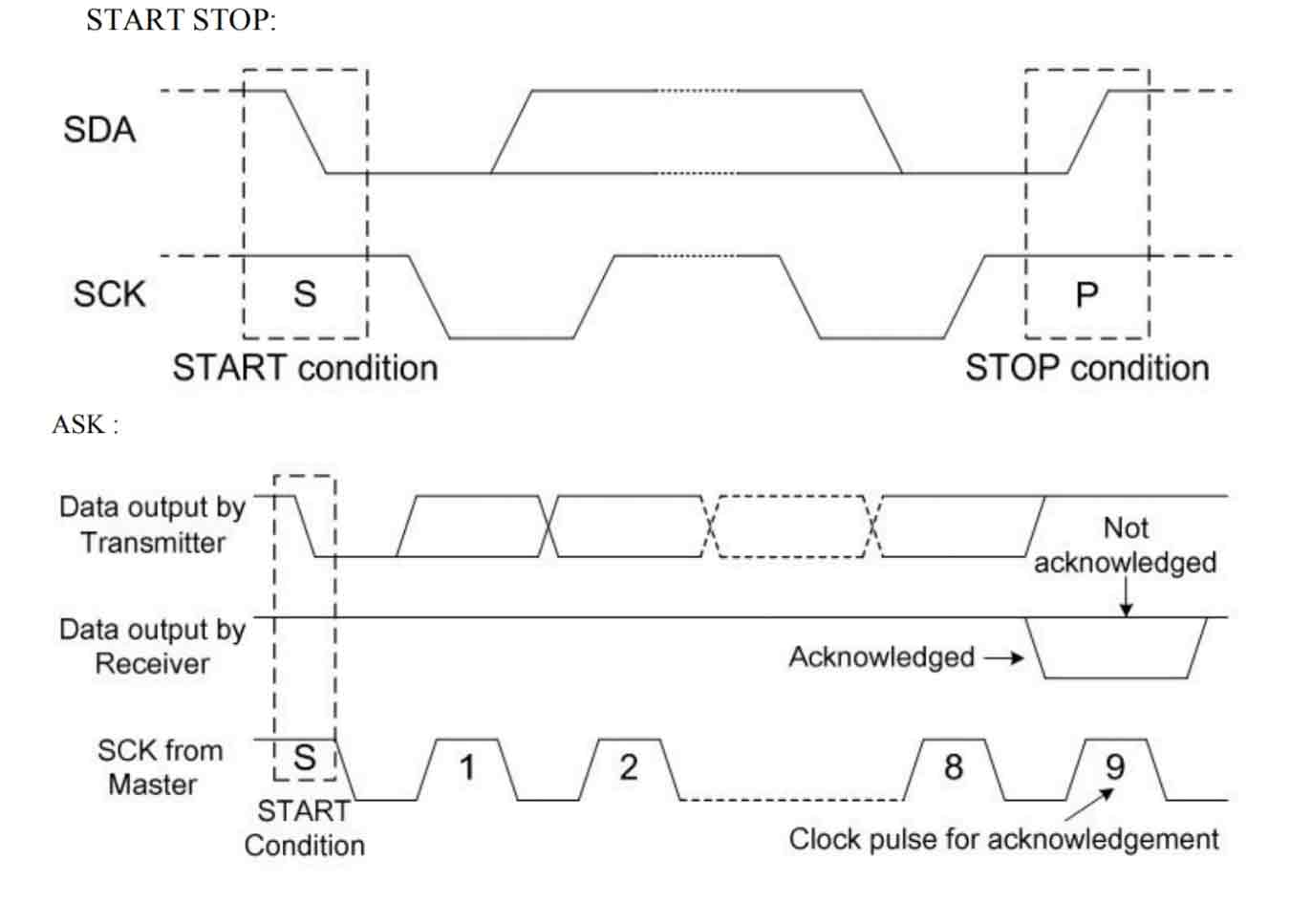
Communication Protocol
Working With Raspberry Pi
Hardware Setting
Enable I2C Interface
Open the Raspberry Pi terminal, enter the following command to enter the configuration interface.
sudo raspi-config
Select Interfacing Options -> I2C ->yes to start the i2C kernel driver
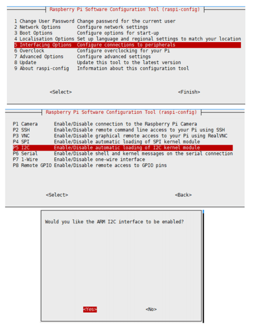
And then reboot the Raspberry Pi.
sudo reboot
Hardware Connection
When connecting the Raspberry Pi, choose to connect with a 4PIN cable, please refer to the pin correspondence table below.
If you are using a pin header or PH2.0 4PIN interface, you need to connect according to the following table.
| LCD | Raspberry Pi | |
| BCM2835 | Board Pin No. | |
| VCC | 3.3V | 3.3V |
| GND | GND | GND |
| SCL | SCL.1 | 5 |
| SDA | SDA.1 | 3 |
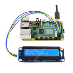
Take the LCD1602 Module using the PH2.0 4PIN interface as an example, and connect it to the Raspberry Pi according to the above table:
(Please connect according to the pin definition table. The color of the cable in the picture is for reference only, and the actual color shall prevail.) 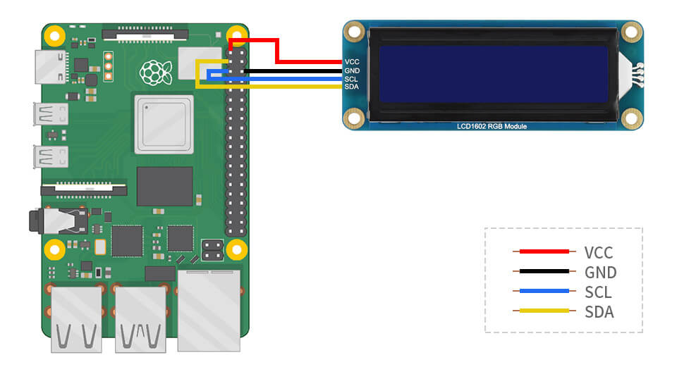
Example Demo
#Download sample demo
cd ~
wget https://www.waveshare.com/w/upload/d/db/LCD1602_I2C_Module_code.zip
unzip LCD1602_I2C_Module_code.zip
cd ~/LCD1602_I2C_Module_code/Raspberry
sudo chmod 777 *
cd python/
sudo python test.py #Display two lines of characters on the LCD
sudo python time_test.py #Automatically obtains the local time and displays it on the LCD- Demo analysis
test.py
lcd.setCursor(0, 0) #Set the cursor position
#Print the number of seconds since reset:
lcd.printout("Waveshare") #Write characters
lcd.setCursor(0, 1) #Set the cursor position to the zeroth column of the second row
lcd.printout("Hello, World!")#Write characters
Working With Pico
Environment Setting
1. Raspberry Pi environment settings, please click to view the link.
2. Windows environment settings, please click to view the link.
Hardware Connection
| Module Interface | Pico Pin |
| VCC | 3.3V |
| GND | GND |
| SCL | GP5 |
| SDA | GP4 |
The physical connection diagram is as follows: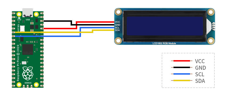
Raspberry Pi
1. Use SSH to log in to the Raspberry Pi terminal or press Ctrl+Alt+T while using the screen to open the terminal.
2. Download and decompress the demo to the Pico C/C++ SDK directory, and the users who have not installed SDK can refer to tutorial.
#Pay attention to your own directory, the default installation directory of the SDK installation tutorial is ~/pico/, if the user customizes other directories, change it by yourself
wget https://www.waveshare.com/w/upload/d/db/LCD1602_I2C_Module_code.zip
unzip LCD1602_I2C_Module_code.zip
cd LCD1602_I2C_Module_code/Pico
micro python
1. Configure settings according to the python environment, using the Raspberry Pi desktop system.
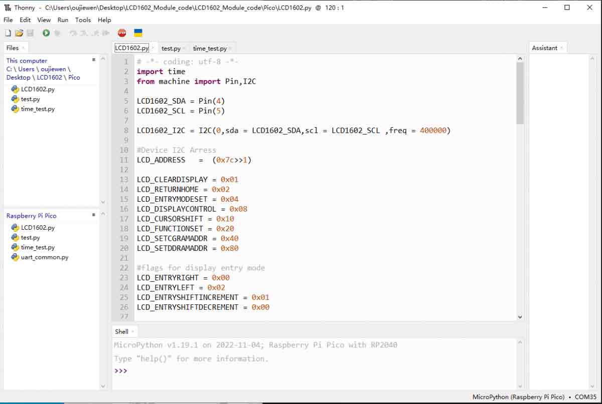
2. Open the Thonny IDE of the Raspberry Pi system, pull the code file into the IDE, and save LCD1602.py to the Pico file system (refer to the Window operation module below), as shown in the figure.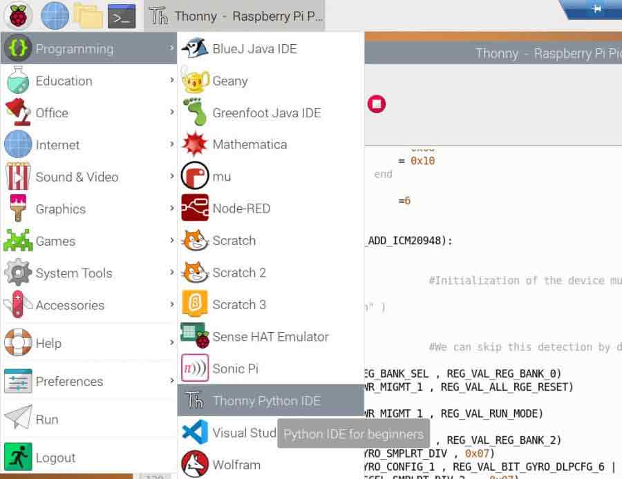
Windows
micro python
- Download and decompress the sample program to the Windows desktop, open the pico corresponding file, refer to the Windows software environment settings.
- Open the downloaded sample program in Thonnty, as shown in the figure below.
Here you also need to save LCD1602.py to PICO, select LCD1602.py, save it as Raspberry pi pico, and name it LCD1602.py.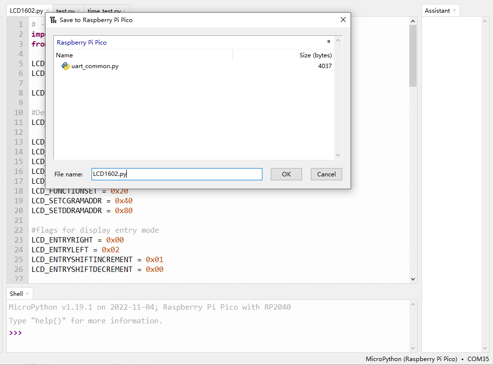
Finally, just run the demo under test.py or time_test.py.
- Demo analysis:
test.py
lcd.setCursor(0, 0) #Set the cursor position
# print the number of seconds since reset:
lcd.printout("Waveshare") #write characters
lcd.setCursor(0, 1) #Set the cursor position to the zeroth column of the second row
lcd.printout("Hello, World!")#write characters
Working With Arduino
Hardware Connection
| Module Interface | Arduino Pin |
| VCC | 5V/3.3V |
| GND | GND |
| SCL | SCL |
| SDA | SDA |
Connection diagram: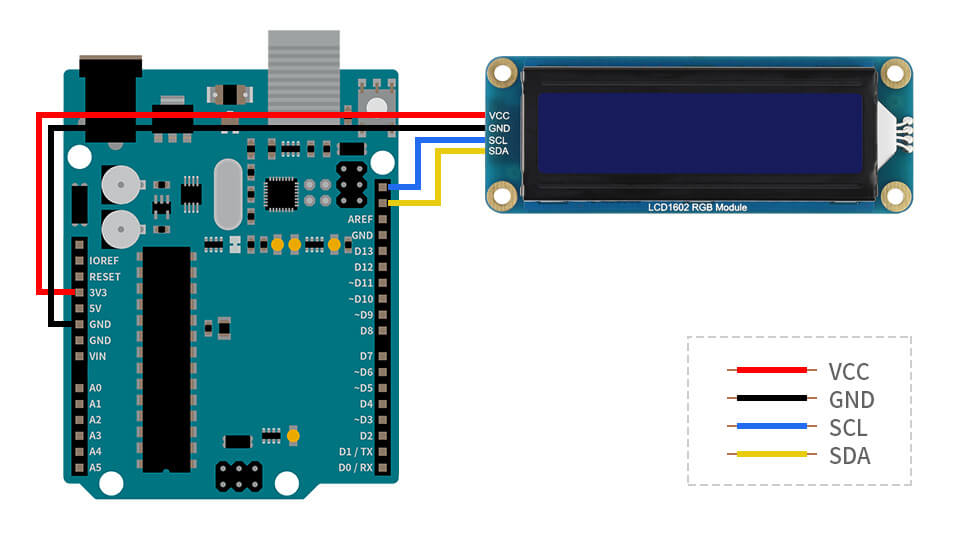
Arduino IDE
Download this sample demo in the Resource, enter the Arduino folder, and double-click to open the test.ino file, Arduino IDE will automatically load the driver library under the same folder, select the correct driver board model and its corresponding port number, click the upload button to automatically start compiling and uploading the demo, and the demo will run automatically after the upload is successful.
This demo has been tested and run on Arduino uno development board and Arduino mega2560 development board.
Working With ESP32
Environment Setting
Install the ESP32 Plug-in in the Arduino IDE
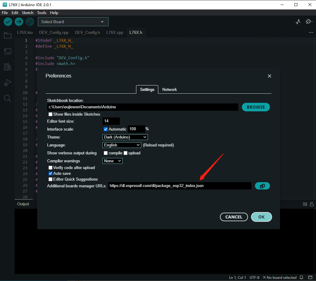
1. Open the Arduino IDE, click on the file in the upper left corner, select Preferences:
2. Add the following link in the additional development board manager URL, then click OK.
https://dl.espressif.com/dl/package_esp32_index.json
Note: If you already have the ESP8266 board URL, you can separate the URLs with commas like this:
https://dl.espressif.com/dl/package_esp32_index.json, http://arduino.esp8266.com/stable/package_esp8266com_index.json
Download the packages compressed package and copy the decompressed packages file to the following path:
C:\Users\xutong\AppData\Local\Arduino15
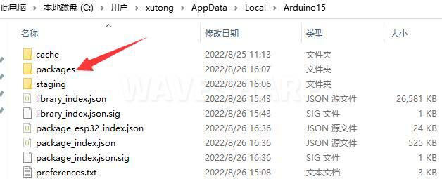
Note: Replace the username: xutong with your own username.
Hardware Connection
When connecting to ESP32, choose to connect with a 4PIN cable, please refer to the pin correspondence table below:
If you are using a pin header or PH2.0 4PIN interface, you need to connect according to the following table.
| LCD | ESP32 | |
| Pin No. | ||
| VCC | 5V/3.3V | |
| GND | GND | |
| SCL | GPIO22 | |
| SDA | GPIO21 | |
Take the LCD1602 Module using the PH2.0 4PIN interface as an example, and connect it to the ESP32 according to the above table:
(Please connect according to the pin definition table. The color of the wiring in the picture is for reference only, and the actual color shall prevail.)
Connect to ESP32 as shown in the figure below.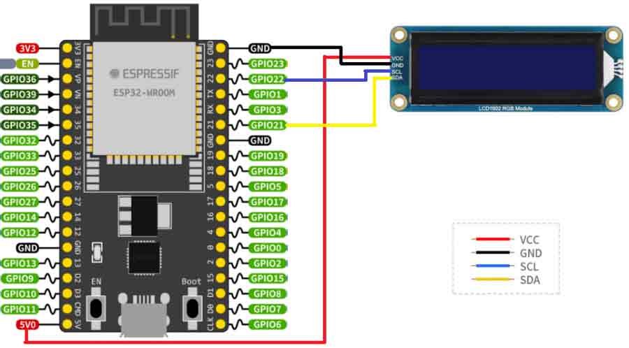
Use With Arduino IDE
Download this sample demo in the Resource, enter the ESP32 folder, double-click to open the test.ino file, Arduino IDE will automatically load the driver library under the same folder, select the correct driver board model and its corresponding port number, click the upload button to automatically Start compiling and uploading the demo, and the demo will run automatically after the upload is successful.
Working With Jetson Nano
Hardware Connection
When connecting Jetson nano, choose to connect with 4PIN cable, please refer to the pin correspondence table below:
If you are using a pin header or PH2.0 4PIN interface, you need to connect according to the following table:
| LCD | Jetson nano | |
| BCM2835 Pin | Board Pin No. | |
| VCC | 3.3V | 3.3V/5V |
| GND | GND | GND |
| SCL | SCL.1 | 5 |
| SDA | SDA.1 | 3 |
Take the LCD1602 Module using the PH2.0 4PIN interface as an example, and connect it to the Jetson nano according to the above table:
(Please connect according to the pin definition table. The color of the wiring in the picture is for reference only, and the actual color shall prevail.)
Connect to Jetson nano as shown below: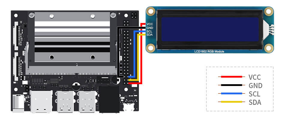
Sample Demo
cd ~
wget https://www.waveshare.com/w/upload/d/db/LCD1602_I2C_Module_code.zip
unzip LCD1602 I2C Module_code.zip
cd ~/LCD1602 I2C Module_code/Jetson\ Nano
sudo chmod 777 *
cd python/
sudo python time_test.py #Automatically obtains the local time and displays it on the LCD