- sales/support
Google Chat:---
- sales
+86-0755-88291180
- sales01
sales@spotpear.com
- sales02
dragon_manager@163.com
- support
tech-support@spotpear.com
- CEO-Complaints
zhoujie@spotpear.com
- Only Tech-Support
WhatsApp:13246739196
- Purchase/Shipping/Refund
WhatsApp:13424403025
- HOME
- >
- ARTICLES
- >
- Common Moudle
- >
- Sensors
TOF MINIF Range Sensor User Guide
Overview
Introduction
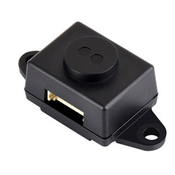
The laser ranging module is based on the D-TOF single-point laser sensor, with a built-in MCU and completed housing packaging. It has sunlight suppression and smudge compensation algorithms to quickly and accurately measure the target distance. It adopts high-precision optical collimation technology, capable of stably measuring the distance of different targets even in a 100K Lux strong light environment.
Disclaimer
| Life Support Policy |
| The TOF MINIF Range Sensor series is not authorized for use in safety-critical applications (such as life support), where a failure of the TOF MINIF Range Sensor series products may cause severe personal injury or death. The Customers who use or sell the TOF MINIF Range Sensor series products in such a manner do so entirely at their risk and agree to fully indemnify Waveshare and its representatives against any damages arising out of the use of TOF MINIF Range Sensor series products in such safety-critical applications. |
| Management Approval |
| The TOF MINIF Range Sensor series supplied by Waveshare has been certified by the European Union for laser products, and it is the user's responsibility to confirm whether these certifications are applicable depending on the region in which they are used or sold. All products developed by users that include the TOF MINIF Range Sensor series sensors must be approved by the relevant regulatory authorities responsible for managing laser products in any given jurisdiction before being sold or marketed within that jurisdiction, and users should be responsible for obtaining approval from the relevant regulatory authorities as needed. |
Usage Scenarios
- Ceiling height determination
- Robot obstacle avoidance
- Measurement and detection
- Intelligent gesture control
- Material level measurement
Operating Principle
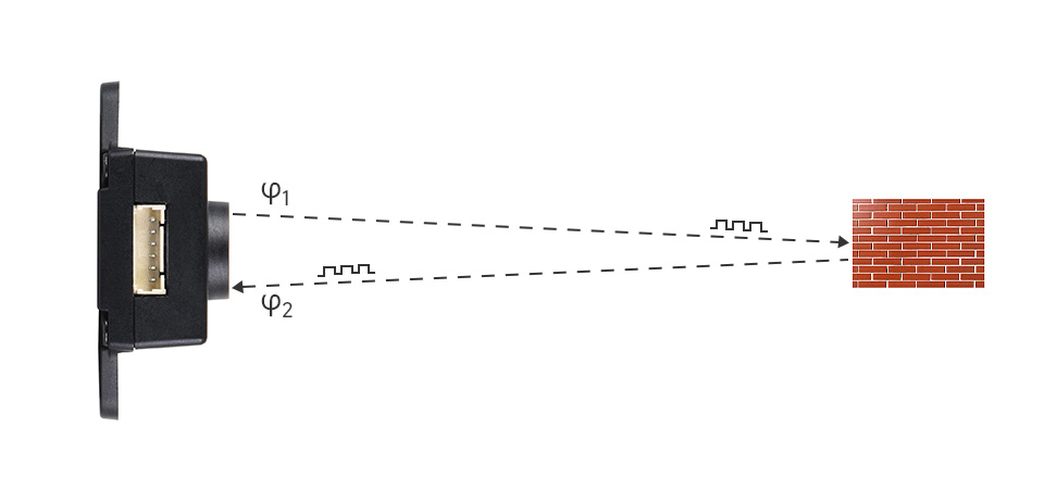
TOF is an absolute distance detection technology, which means that the sensor emits near-infrared light that has been debugged and reflects it when it encounters an object. The sensor calculates the time difference or phase difference between the light emission and reflection, converts it into the distance of the captured object, and generates depth information. Compared to binocular and 3D structured light schemes, TOF has the advantages of longer working distance, wider applicability in various scenarios, and higher accuracy at longer distances. Therefore, it is often applied in situations such as personnel proximity detection, robot obstacle avoidance, and camera autofocus.
Specifications
| Product | TOF Laser Range Sensor | TOF Laser Range Sensor (C) | TOF Laser Range Sensor (D) | TOF Laser Range Sensor Mini | TOF MINIF Range Sensor |
|---|---|---|---|---|---|
| Typical range of distance measurement | Short distance: 0.012 ~ 2.16m | 0.05 ~ 25.0m | 0.05 ~ 50.0m | 0.02 ~ 7.8m | 0.02 ~ 20m |
| Medium distance: 0.012 ~ 3.60m | |||||
| Long distance: 0.01 ~ 5.00m | |||||
| Typical ranging accuracy | Short distance: Accuracy ±1.0cm, Standard deviation <0.3cm | ±3cm standard deviation <1.0cm @0.05~10m, <6.0cm @10~25m | ±3cm standard deviation <1.0cm @0.05~10m, <6.0cm @10~50m | ±4cm standard deviation <2.0cm @0.02~1m, <8.7cm @1~7.8m | <1m@±20mm, >1m@±2% |
| Medium distance: Accuracy ±1.0cm, Standard deviation <1.5cm | |||||
| Long distance: Accuracy ±1.5cm, Standard deviation <0.5cm@0.01~3m, Standard deviation <8cm@3~5m | |||||
| Refresh frequency | 30Hz | 100Hz | 50Hz | 30Hz | |
| Power Supply | 4.3 ~ 5.2V | 4 ~ 5.6V | |||
| Operating temperature | -20°C ~ 65°C | -10℃ ~ 60℃ | |||
| Wavelength | 940nm (Compliant with Class1 standard) | 905nm (Wavelength under review) | 940nm (Wavelength under review) | 940nm | |
| Field of View (FOV) | 15° ~ 27° (Multi-position adjustable) | 1° ~ 2° | 2° ~ 3° | 3°±0.5° | |
| Communication interface | UART (TTL signal cable electrical level 3.3V) | ||||
| CAN (Two interfaces can simultaneously serve as CAN interfaces) | I2C (Support parallel connection of multiple devices, with slave address 0x08+module ID) | - | |||
| I/O (Output complementary electrical level) | - | ||||
| Baud rate | UART: 115.2Kbps ~ 3000Kbps (default 921.6Kbps) | 115200 | |||
| CAN: 100K, 250K, 500K, 1M (default 1M) | I2C: Up to 400Kbps | - | |||
| Cascade quantity | UART interface supports up to 8 cascades, CAN interface supports up to 7 cascades | Up to 8 can be connected in parallel through I2C | |||
| Resistant to ambient light | Weak, about 10K LUX, only supports indoor use | Approximately 100K LUX illumination (suitable for both indoor and outdoor use) | 100K Lux | ||
| Product power consumption | 290mW (UART active output, long-distance mode power supply voltage 5.0V, current 58mA) | 250mW (UART active output, power supply voltage 5.0V, current 50mA) | 100mW (UART active output, long-distance mode power supply voltage 5.0V, current 20mA) | 170mW (UART active output, power supply voltage 5.0V, current 34mA) | |
| Product weight | 2.7g | 7.5g | 1g | 3.6g | |
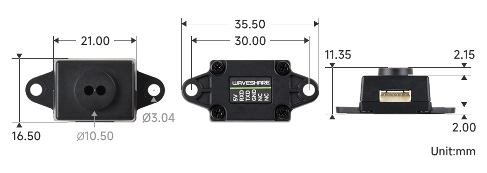
| Length, Width and Height | 35.58mm × 12mm × 8.05mm | 22.7mm × 28mm × 13.6mm | 18.8mm ×12.0mm × 10.3mm | 35.5 x 16.2 x 13.5mm | |
Protocol Parsing
UART Communication Process
- The default configuration of the serial port is: 8-bit data bit, 1-bit stop bit, no parity check, no flow control, and the default baud rate is 115200.
- This protocol specifies that MINIF outputs distance data in ASCII format through UART, and provides ASCII format descriptions to ensure data reliability and parsing consistency.
- The protocol consists of Header, Distance, Separator, Status, and Tail.
- Among them, Header, Separator and Tail are fixed values, please refer to the table below;
- Distance and Status are valid distance values and status;
- The protocol contains the following parts:
Header + Distance + Separator + Status + Tail
- Overview of protocol
| Frame structure | Byte length | Description |
|---|---|---|
| Head | 1 | Frame header |
| Distance | 1-5 | Distance value |
| Separator | 2 | Separator |
| Status | 1-3 | Frame status |
| Tail | 1 | Frame tail |
Example
- Raw data:
20 33 32 37 2C 20 00 0A
- Parsing table:
| Data frame | Example (HEX) | ASCII characters |
|---|---|---|
| Head | 20 | Space |
| Distance | 33 32 37 | 327 |
| Separator | 2C 20 | ,space |
| Status | 00 | 0 |
| Tail | 0A | \n |
- That is, the output distance value of this measurement is 327, in units of mm; A status of 0 indicates that the distance is valid. Among them,
the frame header, separator, and frame tail are all fixed values.
Dimensions
Working with Raspberry Pi
- For the installation and use of the Raspberry Pi system, you can refer to this link.
- After successful boot, configure the Raspberry Pi environment
Download Demo
wget https://files.waveshare.com/wiki/TOF-MINIF-Range-Sensor/TOF_MINIF_Range_Sensor_Demo.zip
unzip TOF_MINIF_Range_Sensor_Demo.zip
cd TOF_MINIF_Range_Sensor_Demo/
UART Demo
Enable Raspberry Pi UART
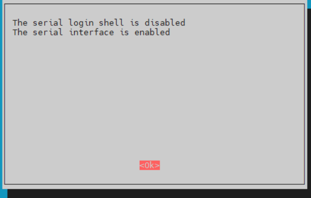
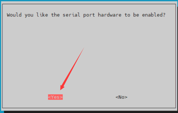
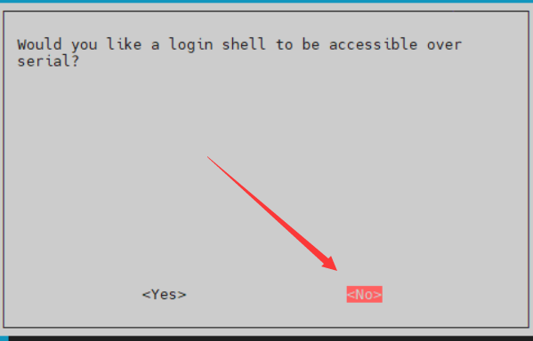
- Enter the command in the Raspberry Pi terminal: sudo raspi-config nonint do_serial 2
- Select NO in the first pop-up window, YES in the second one, and OK for the final one.
Hardware Connection
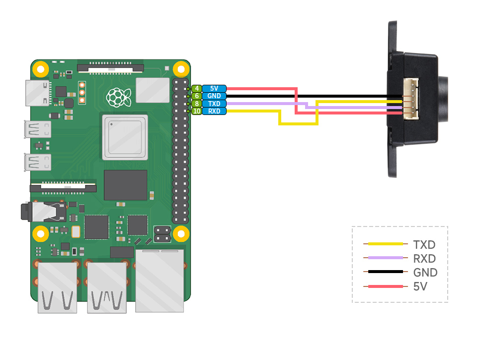
- Refer to the following diagram for connection:
Run C Demo
cd ~/TOF_MINIF_Range_Sensor_Demo/Raspberry/c/
make
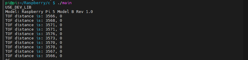
./main
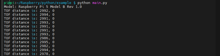
- The terminal will output the relevant information, as shown below:
Run Python Demo
cd ~/TOF_MINIF_Range_Sensor_Demo/Raspberry/python/example
python main.py
- The terminal will output the relevant information, as shown below:
Working with Pico
- For Pico environment setup and basic usage, please refer to this link.
- After setting up the environment, you can connect the sensor and download the Demo
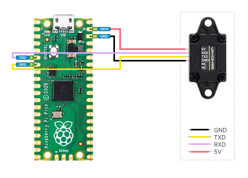
Hardware Connection
- Refer to the following diagram for connection:
Arduino Pico Demos
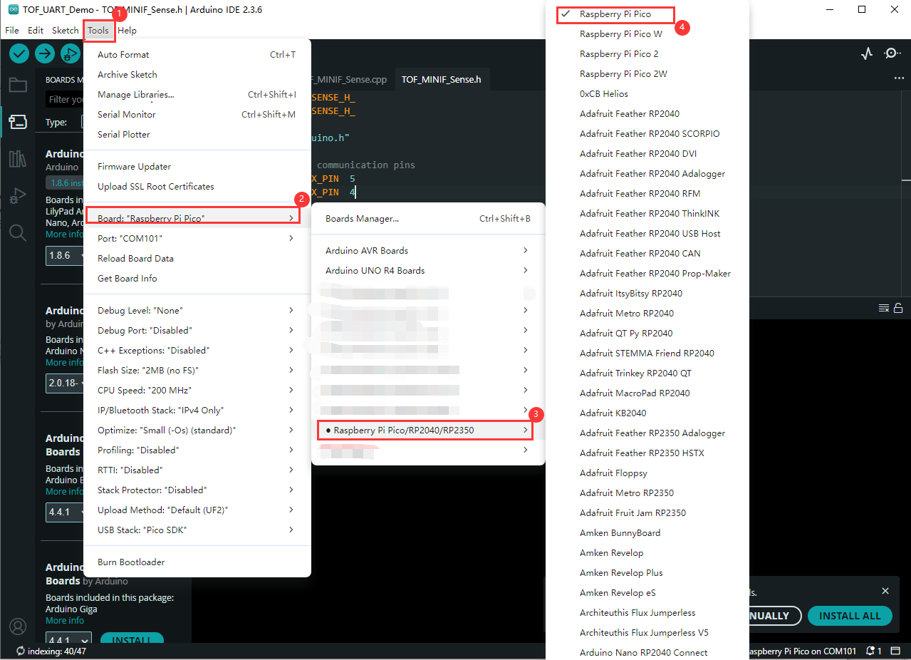
- Go to TOF_MINIF_Range_Sensor_Demo\Pico\Arduino\TOF_URAT_Demo and double-click on the TOF_UART_Demo.ino file
- Select development board:
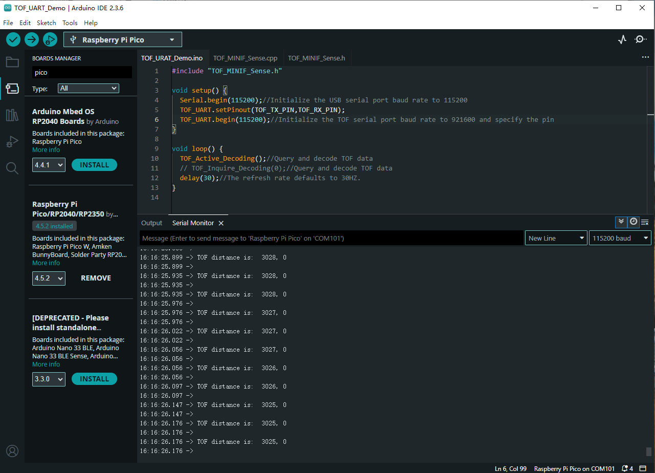
- Select the port of the Pico, and then compile and upload it
- After the upload is completed, open the serial port monitor, and the relevant information will be output, as shown below:
Micropython Demos
- Go to TOF_MINIF_Range_Sensor_Demo\Pico\micropython and double-click on the TOF_UART_Demo.py file
- Select development board:
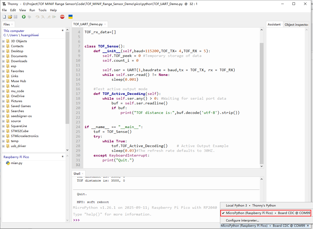
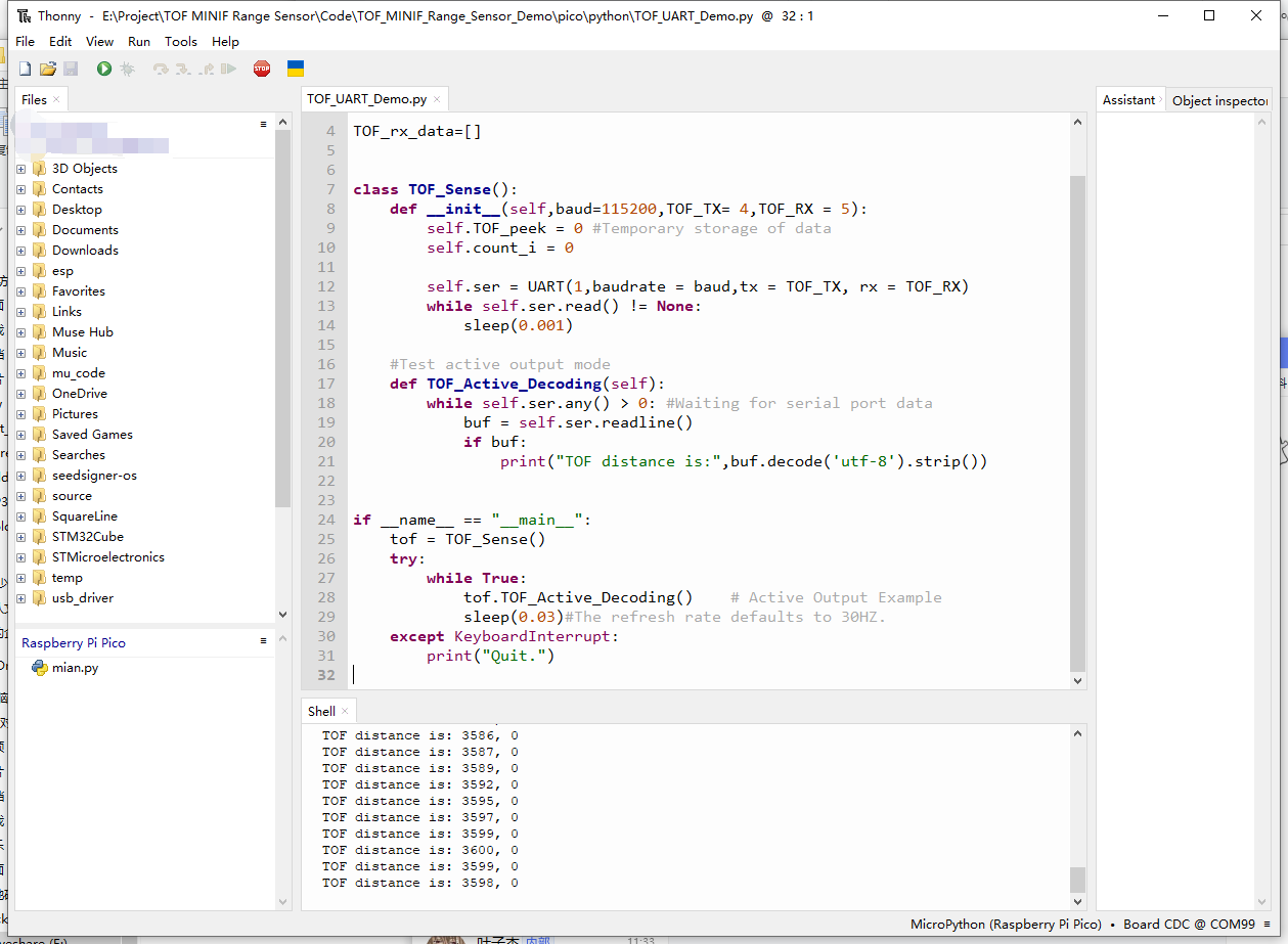
- Select the port of the Pico, and then run the demo
- The shell will output the relevant information, as shown below:
C Demo
- Go to TOF_MINIF_Range_Sensor_Demo\Pico\c and open this folder with VS Code
- In the Pico tool, import this project:
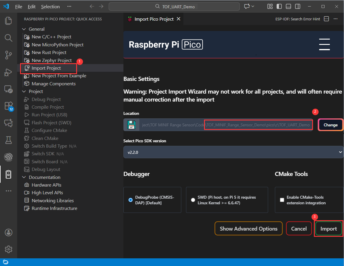
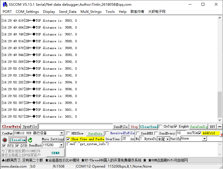
- After import is successful, click Compile to compile. After compilation is successful, put Pico into boot mode and copy the UF2 firmware to the RP2040 disk
- Opening the serial port debugger will output relevant information, as shown in the following figure:
Working with ESP32S3
- For ESP32S3 environment setup and basic usage, please refer to this link.
- After setting up the environment, you can connect the sensor and download the Demo
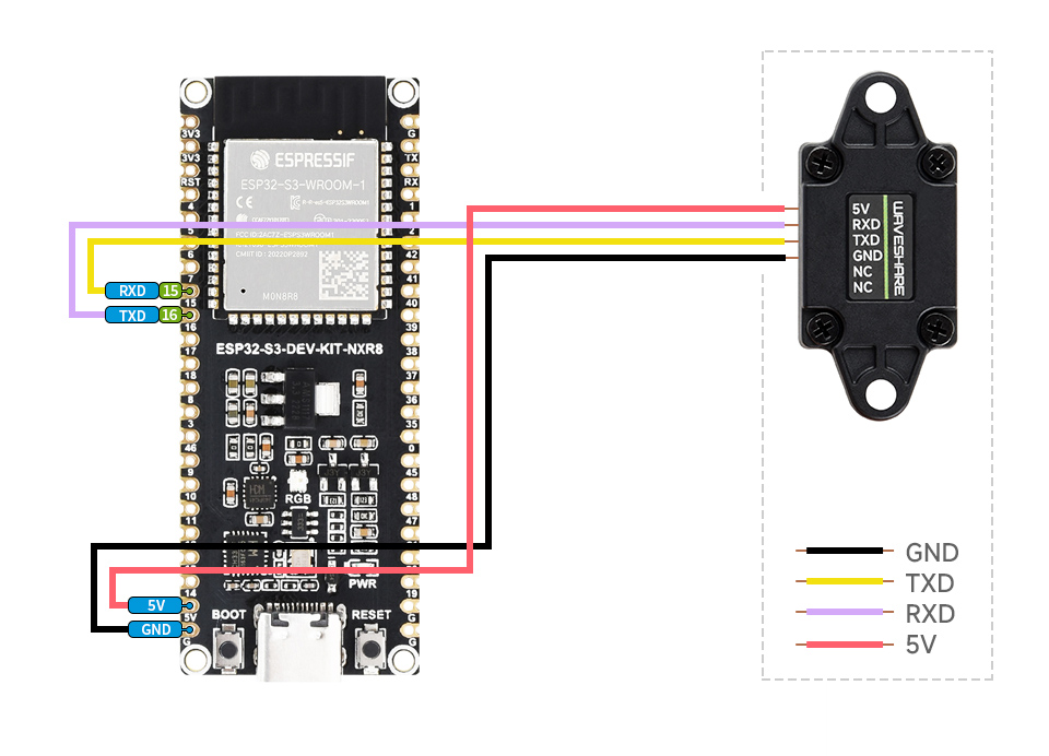
Hardware Connection
- Refer to the following diagram for connection:
Arduino esp32 Demos
- Go to TOF_MINIF_Range_Sensor_Demo\ESP32S3\Arduino\TOF_URAT_Demo and double-click on the TOF_UART_Demo.ino file
- Select development board:
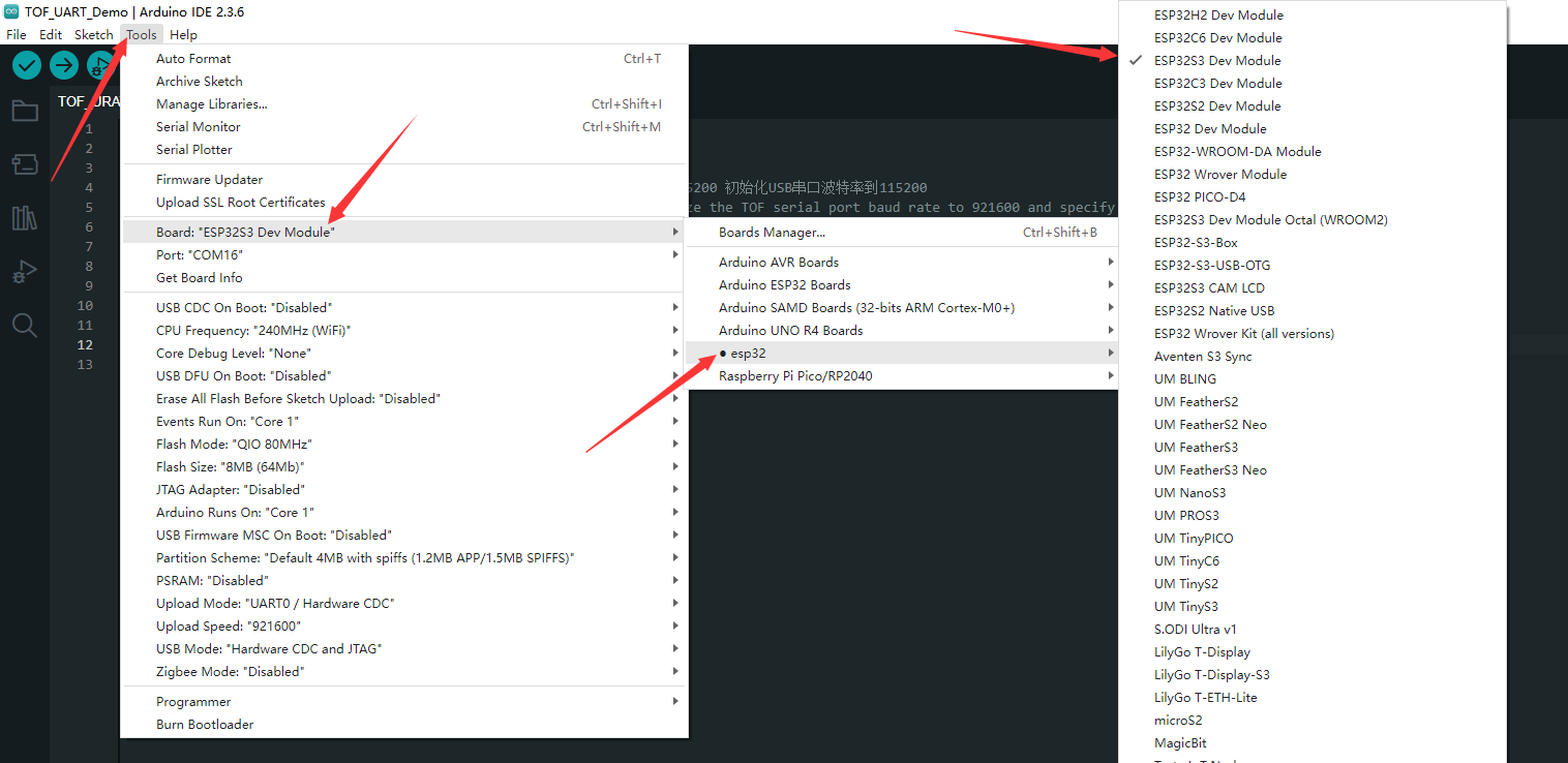
- Select the port of the ESP32S3, and then compile and upload it
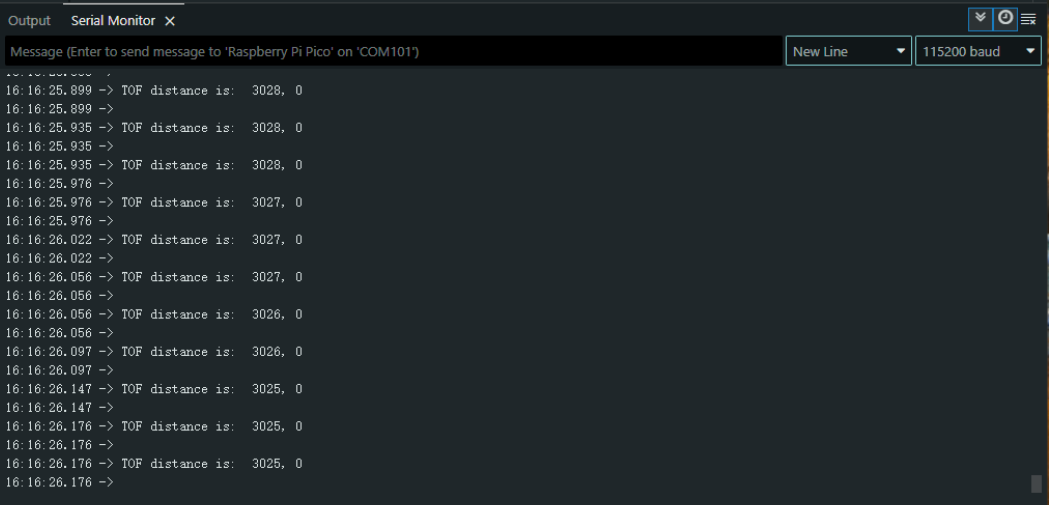
- After the upload is completed, open the serial port monitor, and the relevant information will be output, as shown below:
Micropython Demos
- Go to TOF_MINIF_Range_Sensor_Demo\ESP32S3\micropython and double-click on the TOF_UART_Demo.py file
- Select development board:
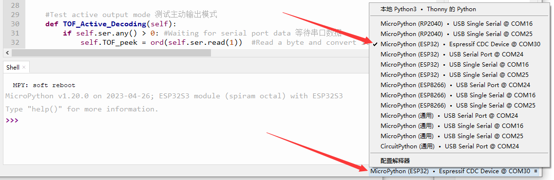
- Select the port of the ESP32S3, and then run the demo
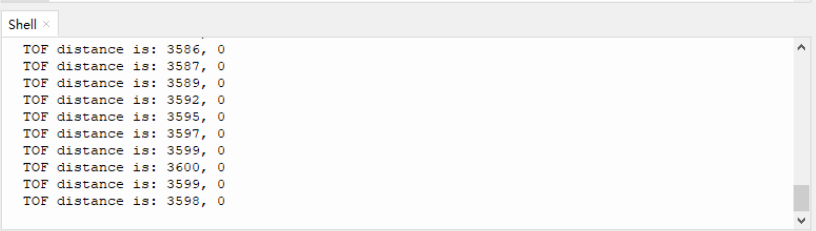
- The shell will output the relevant information, as shown below:
Working with Arduino
- For Arduino environment setup and basic usage, please refer to this R4 link, R3 is installed by default.
- After setting up the environment, you can connect the sensor and download the Demo
Arduino Demos
Hardware Connection
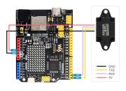
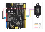
- Refer to the following diagram for connection:
Run Demo
- Go to TOF_MINIF_Range_Sensor_Demo\Arduino\TOF_URAT_Demo and double-click on the TOF_UART_Demo.ino file
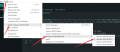
- Select development board:
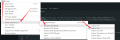
- Select the port of the development board, and then compile and upload it
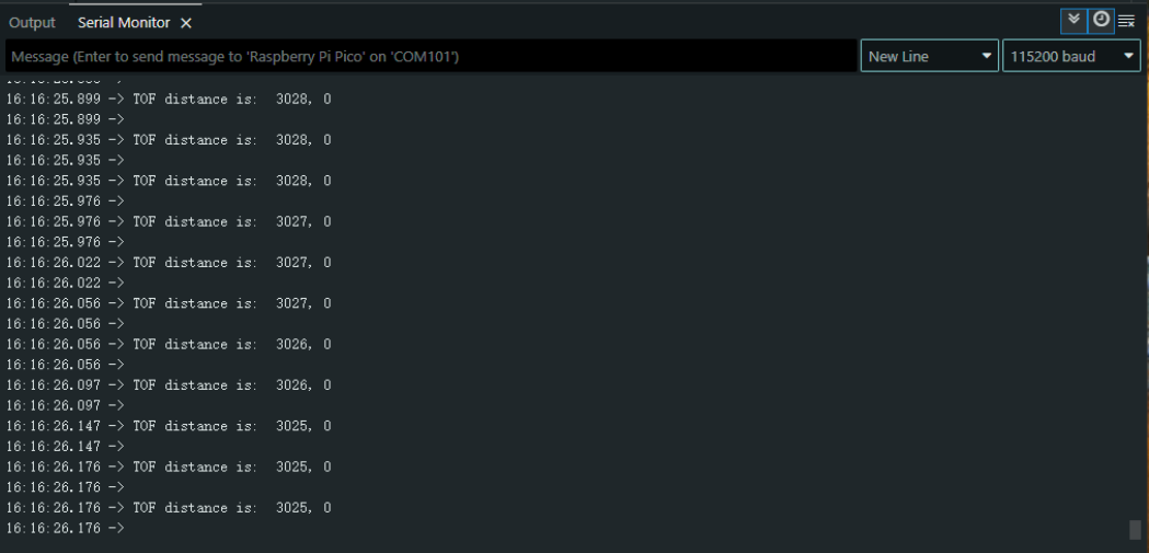
- After the upload is completed, open the serial port monitor, and the relevant information will be output, as shown below:
FAQ
Support
Monday-Friday (9:30-6:30) Saturday (9:30-5:30)
Email: services01@spotpear.com