- sales/support
Google Chat:---
- sales
+86-0755-88291180
- sales01
sales@spotpear.com
- sales02
dragon_manager@163.com
- support
tech-support@spotpear.com
- CEO-Complaints
zhoujie@spotpear.com
- sales/support
WhatsApp:13246739196
- HOME
- >
- ARTICLES
- >
- Raspberry Pi
Raspberry Pi Pico 2 User Guide
Overview
Introduction
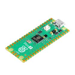
Raspberry Pi Pico 2 is a low-cost, high-performance microcontroller board with flexible digital interfaces. It incorporates Raspberry Pi's own RP2350 microcontroller chip, with unique dual-core and dual-architecture design, running up to 150 MHz, embedded 520KB of SRAM and 4MB of on-board Flash memory, as well as 26x multi-function GPIO pins.
For software development, either Raspberry Pi's C/C++ SDK, or the MicroPython is available. There're also complete development resources and tutorials to help you get started easily, and integrate it into end products quickly.
Feature
- RP2350 microcontroller chip designed by Raspberry Pi in the United Kingdom.
- Adopts unique dual-core and dual-architecture design: dual-core Arm Cortex-M33 processor and dual-core Hazard3 RISC-V processor, flexible clock running up to 150 MHz.
- 520KB of SRAM, and 4MB of on-board Flash memory.
- Castellated module allows soldering direct to carrier boards.
- USB 1.1 with device and host support.
- Low-power sleep and dormant modes.
- Drag-and-drop programming using mass storage over USB.
- 26 × multi-function GPIO pins.
- 2 × SPI, 2 × I2C, 2 × UART, 3 × 12-bit ADC, 24 × controllable PWM channels.
- Accurate onboard clock and timer.
- Temperature sensor.
- 12 × Programmable I/O (PIO) state machines for custom peripheral support.
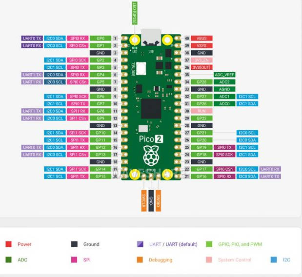
Pinout Definition
Dimensions
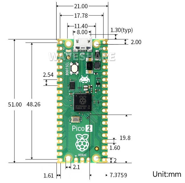
Software Environment Debugging
- To facilitate the development of Pico 2 boards using MicroPython on the computer, it is recommended to download Thonny IDE.
- Download Thonny IDE and install it by steps.
- After installing, please configure the language and the environment for the first time. Note that we should choose the Raspberry Pi option in the board environment.
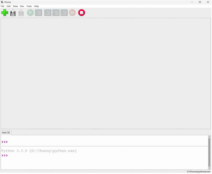
- Configure the Micrpython environment and select the Pico 2 port.
- First connect the Raspberry Pi Pico 2 to the computer, left-click on the configuration environment option in the lower right corner of Thonny--> select configure an interpreter.
- In the pop-up window bar, select MicroPython (Raspberry Pi Pico), and select the corresponding port.
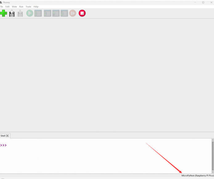
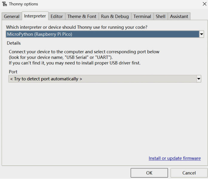
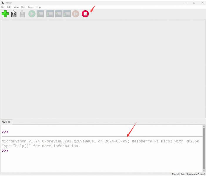
- Click OK to return to the main interface of Thonny, download the firmware library to Pico, and then click the stop button to display the currently used environment in the Shell window.
- Pico 2 download firmware library method in windows: Press and hold the BOOT button and connect to the computer, release the BOOT button, and a removable disk will appear on the computer and copy the firmware library into it.
- How to download the firmware library of RP2350 in windows: After connecting to the computer, press the BOOT key and RESET key at the same time, first release the RESET key and then release the BOOT key, the computer will appear in a removable disk, the firmware library can be copied into it (Pico2 can also be used in the same way).
Examples
- Download Raspberry-Pi-Pico-Basic-Kit Demo to your Raspberry Pi and test.
External LED Example
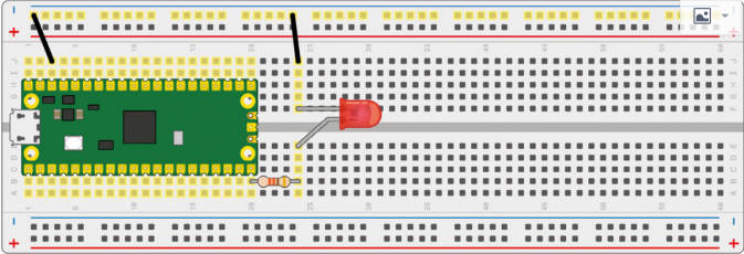
- Connect the boards as in the picture below. Connect the Pico 2 to the Micro USB connector of the PC. Open the python file of Lesson-5 External LED example with Thonny. Run the example, and you will find that the red LED is flashing.
- Note: The longer LED pin is positive, the shorter one is negative, the negative should be connected to GND, the positive should be connected to the GPIO output port, and must be connected to the resistor when used.
- Codes:
led_external = machine.Pin(15, machine.Pin.OUT) #Set GP15 to output Mode
while True:
   led_external.toggle() #Toggle the LED every 5 seconds.
   utime.sleep(5)
Traffic Light System Examples
- Connect the hardware according to the following figure, connect the micro USB to the computer, open the python file in the example program Lesson-9 Traffic-Light-System in Thonny, run the program you can see the normal operation of the traffic light strip, when pressing the key will trigger the buzzer.
- Note: The longer LED pin is positive, the shorter one is negative, the negative should be connected to GND, the positive should be connected to the GPIO output port, must be connected to the resistor; the red line of the buzzer is connected to the output of the GPIO port, and the black line is connected to GND.

- Codes
def button_reader_thread():  #Check if the button is pressed
   global button_pressed
   while True:
       if button.value() == 1:
           button_pressed = True

_thread.start_new_thread(button_reader_thread, ()) #Start a new thread to monitor the stats of button
while True:
   if button_pressed == True: #If the button is pressed, turn on the LED and let the buzzer work
       led_red.value(1)
       for i in range(10):
           buzzer.value(1)
           utime.sleep(0.2)
           buzzer.value(0)
           utime.sleep(0.2)
       global button_pressed
       button_pressed = False
   led_red.value(1)  #Generally, the yellow light will be on for two seconds when the light changes from red to green, then the yellow and red lights will be off and the green light will be on
   utime.sleep(5)     #When the light changes from green to red, the green light is off first, the yellow light is on for two seconds, and then the red light is on
   led_amber.value(1)
   utime.sleep(2)
   led_red.value(0)
   led_amber.value(0)
   led_green.value(1)
   utime.sleep(5)
   led_green.value(0)
   led_amber.value(1)
   utime.sleep(5)
   led_amber.value(0)
Burglar Alarm LED Buzzer Examples
- Connect the hardware according to the following figure, connect the micro USB to the computer, open the python file in the example program Lesson-14 Burglar Alarm LED Buzzer in Thonny, run the program and you can see that, when artificially shaking in front of the Passive infrared sensor, the LED light flashes while the The buzzer will also alarm.
- Note: The center pin of the Passive infrared sensor is the data output pin, and the two side pins are connected to VCC and GND respectively.

- Codes
def pir_handler(pin):  #Interrupt handler function, buzzer sounds, led blinks rapidly
   print("ALARM! Motion detected!")
   for i in range(50):
       led.toggle()
       buzzer.toggle()
       utime.sleep_ms(100)
sensor_pir.irq(trigger=machine.Pin.IRQ_RISING, handler=pir_handler)#Enable the interrupt, when the body sensor detects an abnormality will be handled today by the interrupt handler function
while True:  #Changes the status of the LDE every 5 seconds when there are no abnormalities
   led.toggle()
   utime.sleep(5)
Potentiometer Example
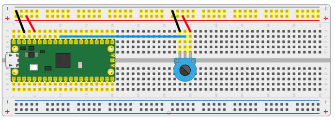
- Connect the hardware according to the following diagram, connect the micro USB to the computer, open the python file in the example program Lesson-16 Potentiometer in Thonny, run the program, rotate the potentiometer to see the voltage value printed out in the Sheel window is also changing.
- Note: The center pin of Potentiometer is the data output port, and the pins on both sides are connected to GND and VCC respectively.
- Codes
potentiometer = machine.ADC(26) #Set the GP26 pin as analog input
conversion_factor = 3.3 / (65535)
while True:
   voltage = potentiometer.read_u16() * conversion_factor #Convert the sampled data to voltage value
   print(voltage) #Print the voltage data, it chanaged according to the sliding rheostat.
   utime.sleep(2)
WS2812 Example
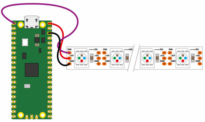
- Connect the hardware according to the following figure, connect the micro USB to the computer, open the WS2812_RGB_LED.py file in the example program Lesson-25 WS2812 in Thonny, and run the program to see the RGB colors of blue, red, green, and white at one time.
- Code
#This code uses the state machine mechanism. The following code is a decorator where we can initialize the hardware, set the pin level, etc.
#label("bitloop") We can define some tags in our code so that we can jump to them.
#jmp(not_x,"do_zero") If x=0, we jumpt to do_zero.
#nop() .set(0) [T2 - 1] The code jumpt to here if x = 0.
@asm_pio(sideset_init=PIO.OUT_LOW, out_shiftdir=PIO.SHIFT_LEFT, autopull=True, pull_thresh=24)
def ws2812():
   T1 = 2
   T2 = 5
   T3 = 1
   label("bitloop")
   out(x, 1)               .side(0)    [T3 - 1]
   jmp(not_x, "do_zero")   .side(1)    [T1 - 1]
   jmp("bitloop")          .side(1)    [T2 - 1]
   label("do_zero")
   nop()                   .side(0)    [T2 - 1]
# Create the StateMachine with the ws2812 program, outputting on Pin(22).
sm = StateMachine(0, ws2812, freq=8000000, sideset_base=Pin(0)) #Create the state machine
# Start the StateMachine, it will wait for data on its FIFO.
sm.active(1) #Start the stats machine
# Display a pattern on the LEDs via an array of LED RGB values.
ar = array.array("I", [0 for _ in range(NUM_LEDS)])
print(ar)
print("blue")
for j in range(0, 255):
   for i in range(NUM_LEDS):
       ar[i] = j
   sm.put(ar,8)  #put() is put the data to output FIFO of the stats machine
   time.sleep_ms(5)
LCD1602 I2C Example
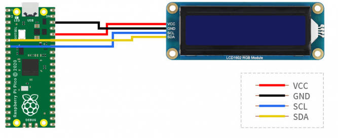
Connect the hardware according to the following figure, connect the micro USB to access the computer, open the python file in the example program Lesson-21 LCD1602 I2C in Thonny, first save the RGB1602.py file as Raspberry Pi Pico2, run Choose_Color.py can see every 5 seconds Switch a different color; run Discoloration.py to see the effect of RGB color gradient.
- Codes
Choose_Color.py
#Define colors
rgb9 = (0,255,0) #green
lcd.setCursor(0, 0) #Set the position of cursor
# print the number of seconds since reset:
lcd.printout("Waveshare") #Print the string
lcd.setCursor(0, 1) #Move the cursor to second row.
lcd.printout("Hello,World!")#Print the string
lcd.setRGB(rgb1[0],rgb1[1],rgb1[2]); #Set the back light
Discoloration.py
t=0
while True:

   r = int((abs(math.sin(3.14*t/180)))*255);  #RGB changes as time goes
   g = int((abs(math.sin(3.14*(t+60)/180)))*255);
   b = int((abs(math.sin(3.14*(t+120)/180)))*255);
   t = t + 3;
   lcd.setRGB(r,g,b);#Set the RGB data again.
# set the cursor to column 0, line 1
   lcd.setCursor(0, 0) #Set the curson to the first row.
# print the number of seconds since reset:
   lcd.printout("Waveshare")#Print the string
   lcd.setCursor(0, 1) #Set the cursor to second row
   lcd.printout("Hello,World!")#Print the string
   time.sleep(0.3)
Resource
Firmware Library
Example Demo
Official Document
Pico2
User Manual
Schematic & Datasheet
Related Resources
Raspberry Pi Open-source Demo
Development Software
- Zimo221.7z
- Image2Lcd.7z
- Font Library Tutorial
- Image Extraction Tutorial
- Thonny Python IDE (Windows V3.3.3)
FAQ
Question:What are the frequent questions for developing with the Raspberry Pi Pico 2?
You can refer to Pico this link.
Question:What can I do if the Raspberry Pi Pico 2 is interfered?
1. The pins set to input state must be initialized to pull high or pull low.
2. Replace the USB cable to see if there is a problem with the USB cable used.
Support
Monday-Friday (9:30-6:30) Saturday (9:30-5:30)
Mobile: +86 13434470212
Email: services01@spotpear.com
[Tutorial Navigation]
- Overview
- Resource
- FAQ
- Question:What are the frequent questions for developing with the Raspberry Pi Pico 2?
- Question:What can I do if the Raspberry Pi Pico 2 is interfered?
- Support


