


- sales/support
Google Chat:---
- sales
+86-0755-88291180
- sales01
sales@spotpear.com
- sales02
dragon_manager@163.com
- support
tech-support@spotpear.com
- CEO-Complaints
zhoujie@spotpear.com
- Only Tech-Support
WhatsApp:13246739196
- Purchase/Shipping/Refund
WhatsApp:13424403025
RP2350-PiZero User Guide
Overview
Introduction
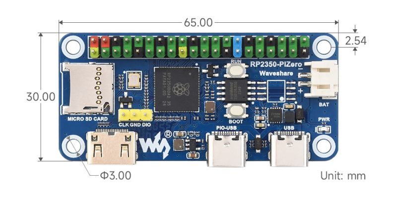
RP2350-PiZero is a high-performance and cost-effective microcontroller board designed by Waveshare. It features a DVI interface, TF card slot and PIO-USB port, and brings out a 40PIN GPIO port compatible with Raspberry Pi. It also reserves one PSRAM pad for easy development and integration into products.
Features
- RP2350B microcontroller chip officially designed by Raspberry Pi
- Unique dual-core and dual-architecture design, equipped with dual-core ARM Cortex-M33 processor and dual-core Hazard3 RISC-V processor, flexible clock running up to 150 MHz, supporting flexible switching between the two architectures
- Built-in 520KB SRAM and 16MB on-chip Flash, with a reserved PSRAM pad
- Type-C connector, easier to use
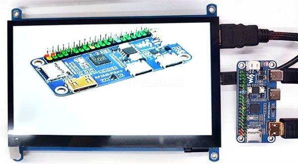
- Onboard DVI port, capable of driving most HDMI screens (compatible DVI port required)
- Supports using as a USB host or slave via onboard PIO-USB port
- Onboard TF card slot for reading and writing TF card
- Onboard Lithium battery recharge/discharge header, suitable for mobile devices
- USB1.1 host and slave device support
- Low-power sleep and dormant modes
- Drag-and-drop programming using mass storage over USB
- 5 × multi-functional GPIO pins
- 2 × SPI, 2 × I2C, 2 × UART, 2 × 12-bit ADC and 16 × controllable PWM channels
- Accurate clock and timer on-chip
- Temperature sensor
- On-chip accelerated floating-point library
- 12 × Programmable I/O (PIO) state machines for custom peripheral support
Dimensions
Pico Getting Started
Firmware Download
- MicroPython Firmware Download

- C_Blink Firmware Download

Basic Introduction
MicroPython Series
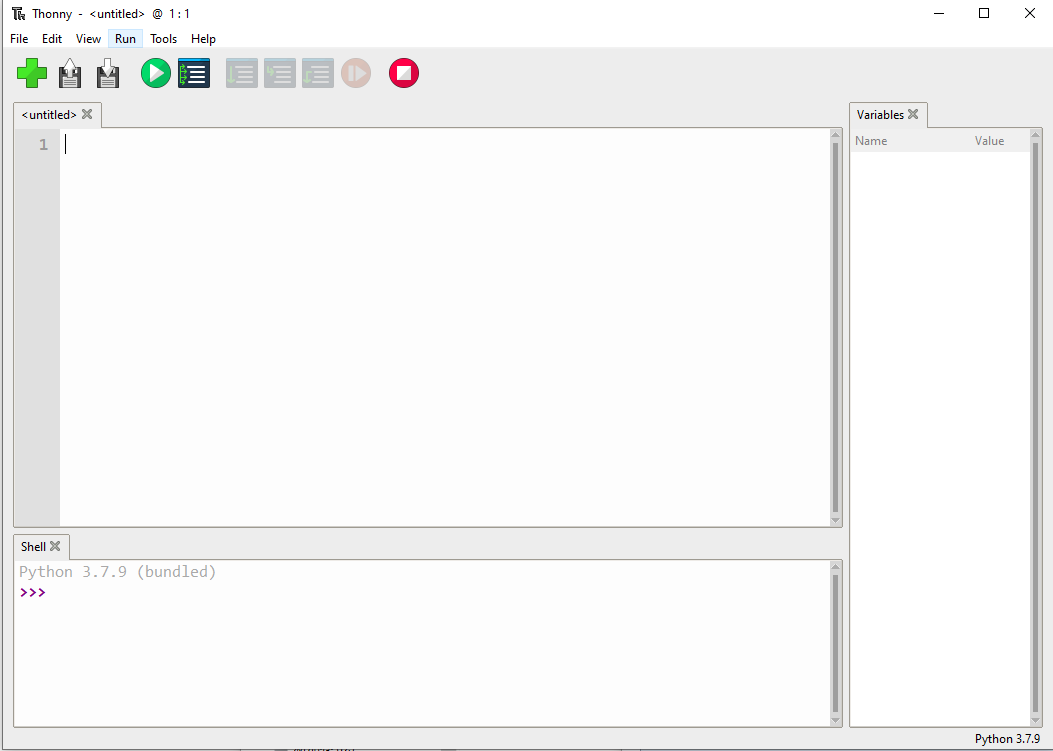
Install Thonny IDE
In order to facilitate the development of Pico/Pico2 boards using MicroPython on a computer, it is recommended to download the Thonny IDE
- Download Thonny IDE and follow the steps to install, the installation packages are all Windows versions, please refer to Thonny's official website for other versions
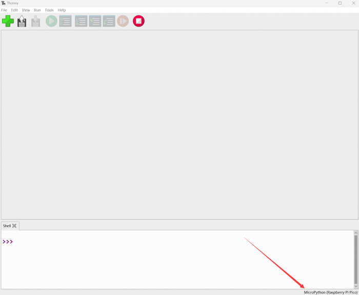
- After installation, the language and motherboard environment need to be configured for the first use. Since we are using Pico/Pico2, pay attention to selecting the Raspberry Pi option for the motherboard environment
- Configure MicroPython environment and choose Pico/Pico2 port
- Connect Pico/Pico2 to your computer first, and in the lower right corner of Thonny left-click on the configuration environment option --> select Configture interpreter
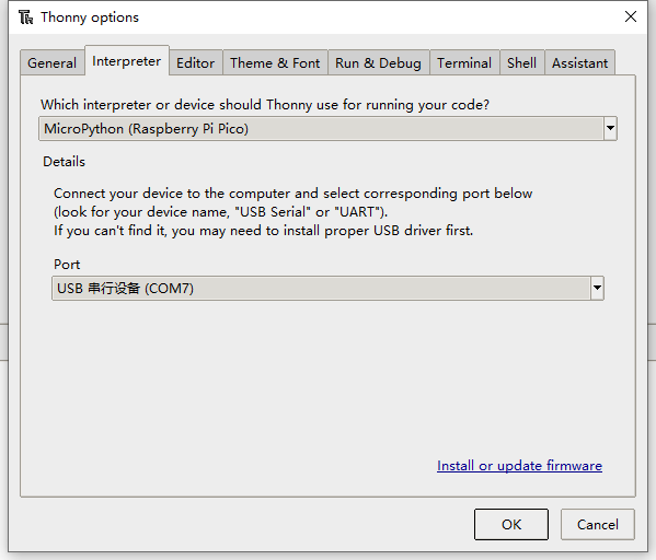
- In the pop-up window, select MicroPython (Raspberry Pi Pico), and choose the corresponding port
Flash Firmware
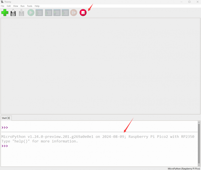
- Click OK to return to the Thonny main interface, download the corresponding firmware library and burn it to the device, and then click the Stop button to display the current environment in the Shell window
- Note: Flashing the Pico2 firmware provided by Micropython may cause the device to be unrecognized, please use the firmware below or in the package
- How to download the firmware library for Pico/Pico2 in windows: After holding down the BOOT button and connecting to the computer, release the BOOT button, a removable disk will appear on the computer, copy the firmware library into it
- How to download the firmware library for RP2040/RP2350 in windows: After connecting to the computer, press the BOOT key and the RESET key at the same time, release the RESET key first and then release the BOOT key, a removable disk will appear on the computer, copy the firmware library into it (you can also use the Pico/Pico2 method)
MicroPython Series Tutorials
【MicroPython】 machine.Pin class function details
【MicroPython】machine.PWM class function details
【MicroPython】machine.ADC class function details
【MicroPython】machine.UART class function details
【MicroPython】machine.I2C class function details
【MicroPython】machine.SPI class function details
【MicroPython】rp2.StateMachine class function details
C/C++ Series
For C/C++, it is recommended to use Pico VSCode for development. This is a Microsoft Visual Studio Code extension designed to make it easier for you to create, develop, and debug projects for the Raspberry Pi Pico series development boards. No matter if you are a beginner or an experienced professional, this tool can assist you in developing Pico with confidence and ease. Here's how to install and use the extension.
- Official website tutorial: https://www.raspberrypi.com/news/pico-vscode-extension/
- This tutorial is suitable for Raspberry Pi Pico, Pico2 and the RP2040 and RP2350 series development boards developed by Waveshare
- The development environment defaults to Windows11. For other environments, please refer to the official tutorial for installation
Install VSCode
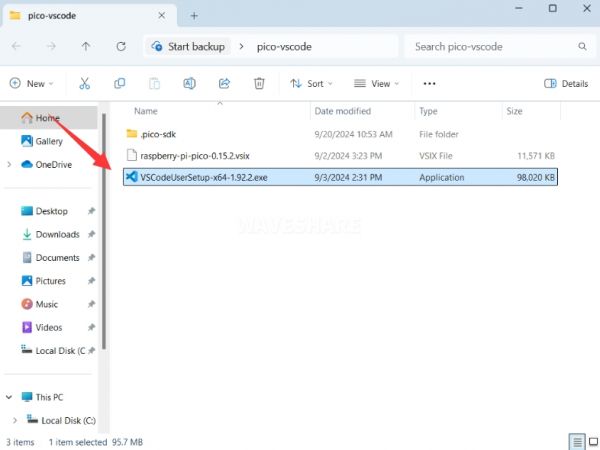
- First, click to download pico-vscode package, unzip and open the package, double-click to install VSCode
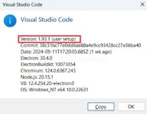
Note: If vscode is installed, check if the version is v1.87.0 or later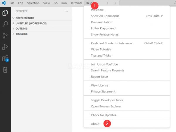
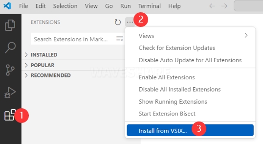
Install Extension
- Click Extensions and select Install from VSIX
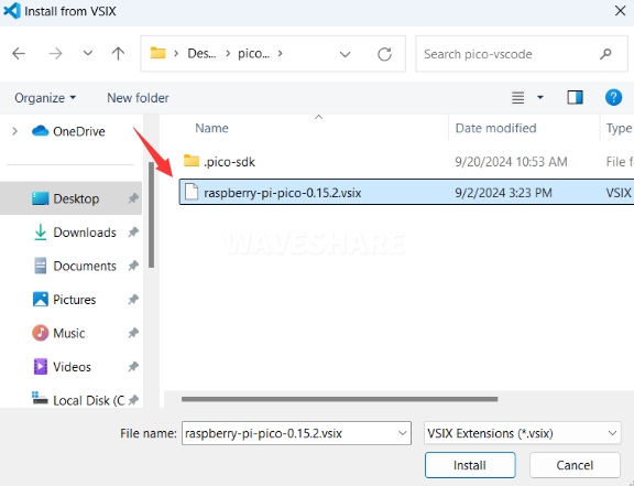
- Select the package with the vsix suffix and click Install
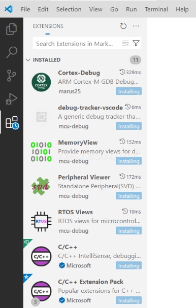
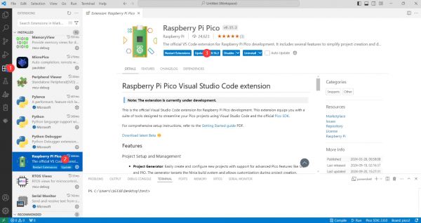
- Then vscode will automatically install raspberry-pi-pico and its dependency extensions, you can click Refresh to check the installation progress
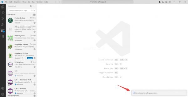
- The text in the right lower corner shows that the installation is complete. Close VSCode
Configure Extension
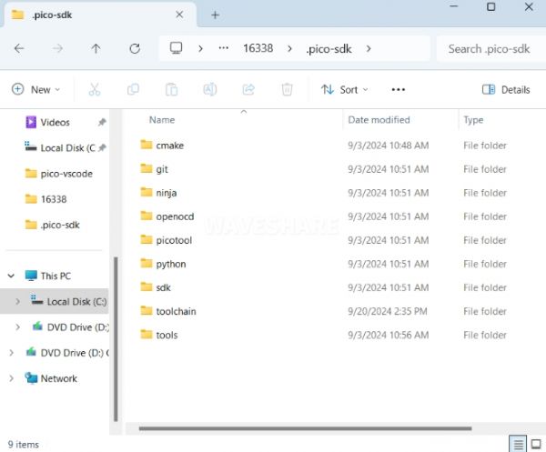
- Open directory C:\Users\username and copy the entire .pico-sdk to that directory
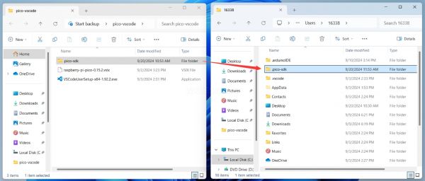
- The copy is completed
- Open vscode and configure the paths for the Raspberry Pi Pico extensions
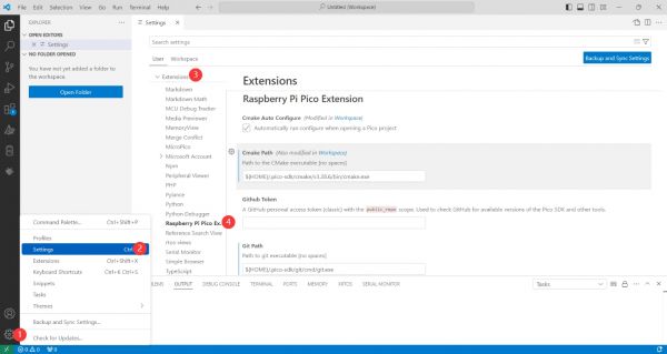
The configuration is as follows:Cmake Path: ${HOME}/.pico-sdk/cmake/v3.28.6/bin/cmake.exe Git Path: ${HOME}/.pico-sdk/git/cmd/git.exe Ninja Path: ${HOME}/.pico-sdk/ninja/v1.12.1/ninja.exe Python3 Path: ${HOME}/.pico-sdk/python/3.12.1/python.exe
New Project
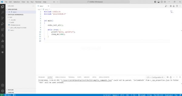
- The configuration is complete, create a new project, enter the project name, select the path, and click Create to create the project
To test the official example, you can click on the Example next to the project name to select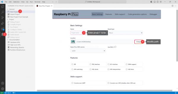
- The project is created successfully
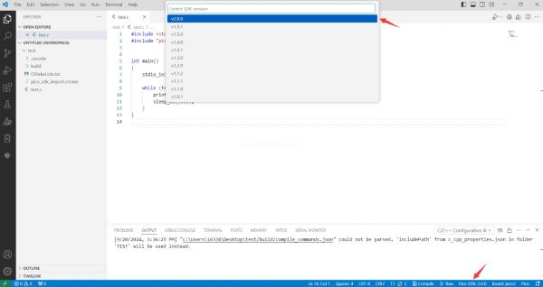
Compile Project
- Select the SDK version
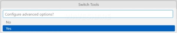
- Select Yes for advanced configuration
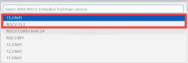
- Choose the cross-compilation chain, 13.2.Rel1 is applicable for ARM cores, RISCV.13.3 is applicable for RISCV cores. You can select either based on your requirements
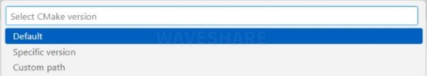
- Select Default for CMake version (the path configured earlier)
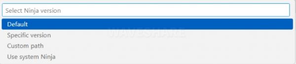
- Select Default for Ninjaversion
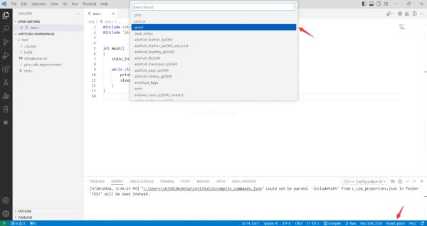
- Select the development board
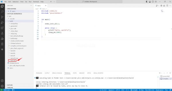
- Click Complie to compile
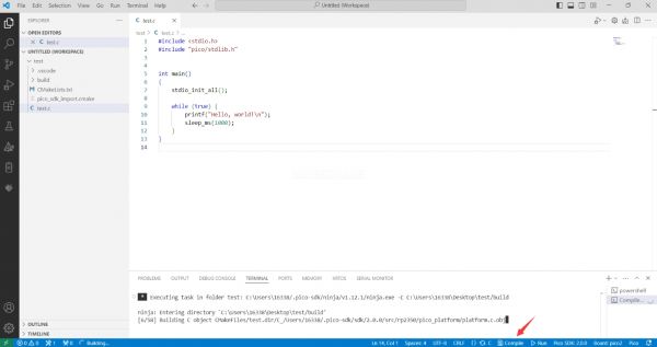
- The uf2 format file is successfully compiled
Flash Firmware
Here are two methods for flashing firmware
- Flash firmware using the pico-vscode plugin
Connect the development board to the computer, click Run to flash the firmware directly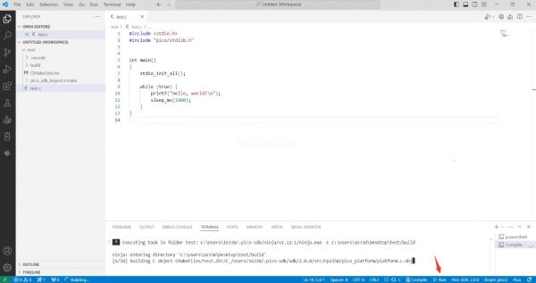
- Flash the firmware manually
1. Press and hold the Boot button
2. Connect the development board to the computer
3. Then the computer will recognize the development board as a USB device.
4. Copy the .uf2 file to the USB drive, and the device will automatically restart, indicating successful program flashing.
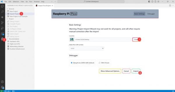
Import Project
- Select the project directory and import the project
- The Cmake file of the imported project cannot have Chinese (including comments), otherwise the import may fail
- To import your own project, you need to add a line of code to the Cmake file to switch between pico and pico2 normally, otherwise even if pico2 is selected, the compiled firmware will still be suitable for pico
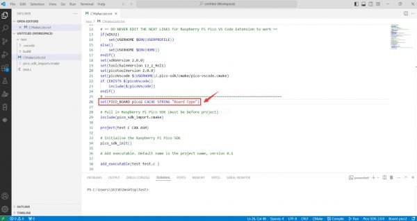
set(PICO_BOARD pico CACHE STRING "Board type")
Update Extension
- The extension version in the offline package is 0.15.2, and you can also choose to update to the latest version after the installation is complete
Arduino IDE Series
Install Arduino IDE
- First, go to Arduino official website to download the installation package of the Arduino IDE.
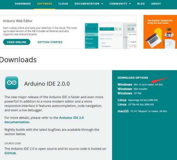
- Here, you can select Just Download.
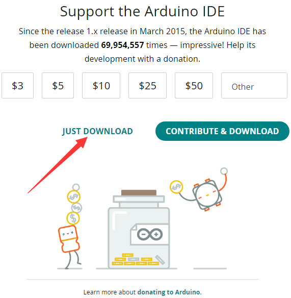
- Once the download is complete, click Install.
Notice: During the installation process, it will prompt you to install the driver, just click Install
Arduino IDE Interface
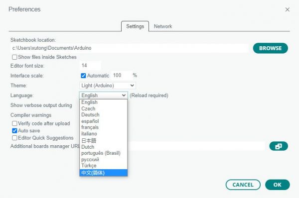
- After the first installation, when you open the Arduino IDE, it will be in English. You can switch to other languages in File --> Preferences, or continue using the English interface.

- In the Language field, select the language you want to switch to, and click OK.
Install Arduino-Pico Core in Arduino IDE
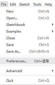
- Open the Arduino IDE, click on the file in the top left corner, and select Preferences
- Add the following link to the attached board manager URL, and then click OK
This link already includes board versions such as RP2040 and RP2350. Please visit arduino-pico for the latest version fileshttps://github.com/earlephilhower/arduino-pico/releases/download/4.5.2/package_rp2040_index.json
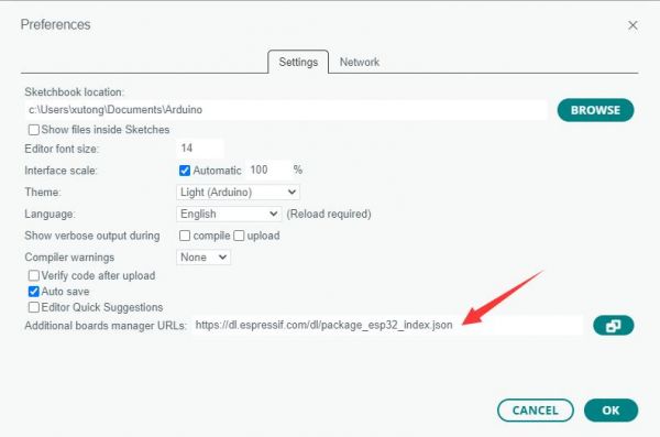
Note: If you already have an ESP32 board URL, you can use a comma to separate the URLs as follows:https://dl.espressif.com/dl/package_esp32_index.json,https://github.com/earlephilhower/arduino-pico/releases/download/4.5.2/package_rp2040_index.json
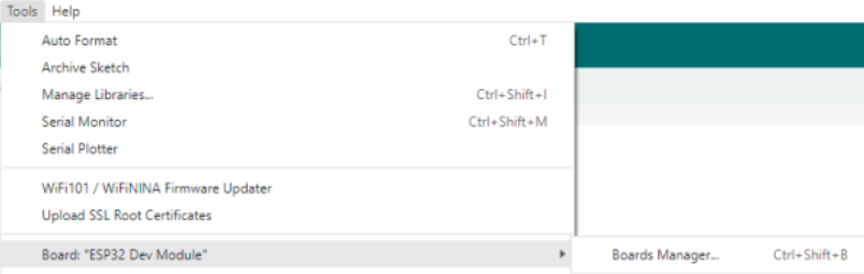
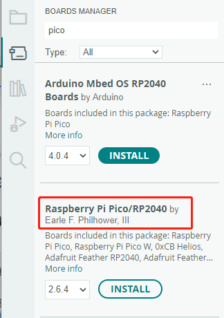
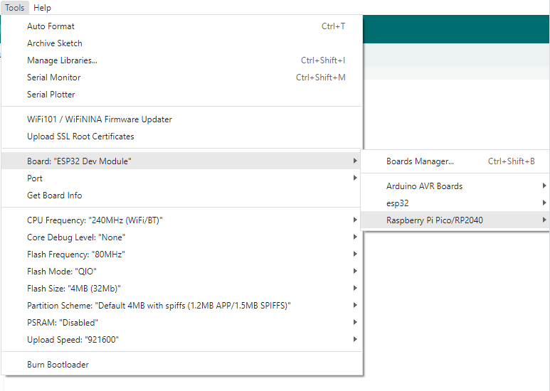
- Click Tools > Board > Board Manager > Search pico, as my computer has already been installed, it shows that it is installed
Upload Demo at the First Time
- Press and hold the BOOTSET button on the Pico board, connect the pico to the USB port of the computer via the Micro USB cable, and release the button after the computer recognizes a removable hard disk (RPI-RP2).
- Download the program and open D1-LED.ino under the arduino\PWM\D1-LED path
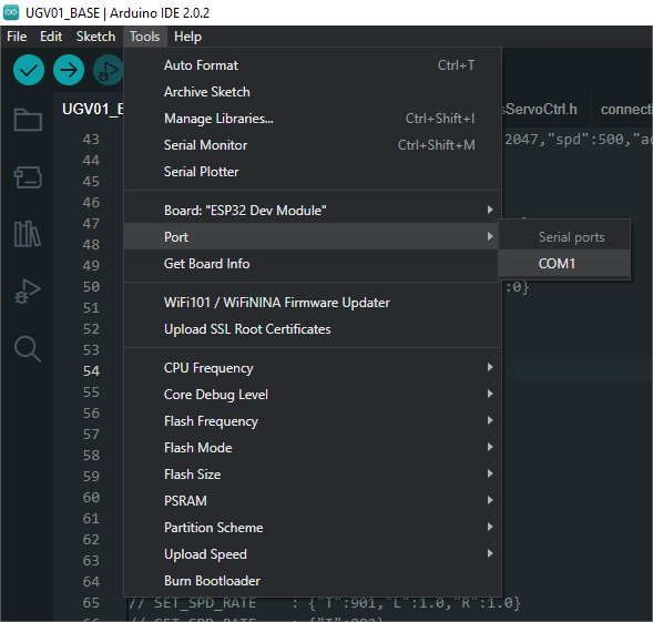
- Click Tools --> Port, remember the existing COM, do not click this COM (the COM displayed is different on different computers, remember the COM on your own computer)
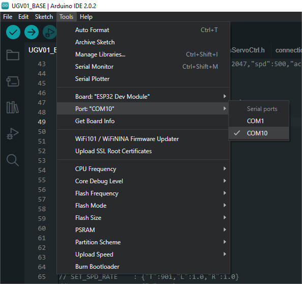
- Connect the driver board to the computer using a USB cable. Then, go to Tools > Port. For the first connection, select uf2 Board. After uploading, when you connect again, an additional COM port will appear
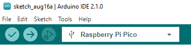
- Click Tools > Development Board > Raspberry Pi Pico > Raspberry Pi Pico or Raspberry Pi Pico 2

- After setting it up, click the right arrow to upload the program
- If issues arise during this period, and if you need to reinstall or update the Arduino IDE version, it is necessary to uninstall the Arduino IDE completely. After uninstalling the software, you need to manually delete all contents within the C:\Users\[name]\AppData\Local\Arduino15 folder (you need to show hidden files to see this folder). Then, proceed with a fresh installation.
Open Source Demos
MircoPython video demo (github)
MicroPython firmware/Blink demos (C)
Raspberry Pi official C/C++ demo (github)
Raspberry Pi official micropython demo (github)
Arduino official C/C++ demo (github)
Demo
C Demo
01-DVI
- The demo is modified based on Wren6991 PicoDVI
Main Directory Analysis
- apps directory: demo source code
- assets directory: original images and image header files
- include directory: default pin configuration header files
- libdvi directory: DVI driver source code
- libgui directory: GUI source code
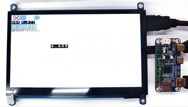
Hello DVI Demo Description
- Hello DVI demo is located in the hello_dvi file under apps directory
- Scroll through a 320x240p RGB565 test image in 640x480p 60Hz DVI mode

Gui Demo Description
- Gui Demo is located in gui demo file under apps directory
- Display white, red, yellow, green, cyan, blue, purple, black, and then the GUI image in 640x480p 60Hz DVI mode
02-USB
- The demo is modified based on sekigon-gonnoc Pico-PIO-USB
Main Directory Analysis
- examples: source code of the demo
- src: source code of the PIO-USB driver
capture_hid_report Demo Description
- capture_hid_report demo is located in capture_hid_report file under examples directory
- PIO-USB will serve as a USB host for receiving and printing HID reports sent by USB devices
usb_device Demo
- usb_device demo is located in the usb_device of the examples directory
- PIO-USB will be emulated as a mouse and move the mouse cursor every 0.5s

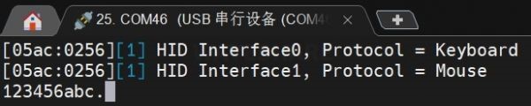
Host_hid_to_device_cdc Demo
- Host_hid_to_device_cdc demo is located in the Host_hid_to_device_cdc of the examples directory
- Host_hid_to_device_cdc is similar to capture_hid_report, printing a mouse/keyboard report from the host port to the CDC of the device port
03-MicroSD
Main Directory Analysis
- tests: source code used for tests
- FatFs_SPI: MicroSD related driver source code
Demo Description
- Using a terminal tool such as putty or mobaxterm, open the USB serial port corresponding to the RP2350-PiZero
- Type Enter and the following message will be displayed
>
- Enter help command to get the available commands as follows
setrtc <DD> <MM> <YY> <hh> <mm> <ss>:
  Set Real Time Clock
  Parameters: new date (DD MM YY) new time in 24-hour format (hh mm ss)
	e.g.:setrtc 16 3 21 0 4 0

date:
 Print current date and time

lliot <drive#>:
 !DESTRUCTIVE! Low Level I/O Driver Test
	e.g.: lliot 1

format [<drive#:>]:
  Creates an FAT/exFAT volume on the logical drive.
	e.g.: format 0:

mount [<drive#:>]:
  Register the work area of the volume
	e.g.: mount 0:

unmount <drive#:>:
  Unregister the work area of the volume

chdrive <drive#:>:
  Changes the current directory of the logical drive.
  <path> Specifies the directory to be set as current directory.
	e.g.: chdrive 1:

getfree [<drive#:>]:
  Print the free space on drive

cd <path>:
  Changes the current directory of the logical drive.
  <path> Specifies the directory to be set as current directory.
	e.g.: cd 1:/dir1

mkdir <path>:
  Make a new directory.
  <path> Specifies the name of the directory to be created.
	e.g.: mkdir /dir1

ls:
  List directory

cat <filename>:
  Type file contents

simple:
  Run simple FS tests

big_file_test <pathname> <size in bytes> <seed>:
 Writes random data to file <pathname>.
 <size in bytes> must be multiple of 512.
	e.g.: big_file_test bf 1048576 1
	or: big_file_test big3G-3 0xC0000000 3

cdef:
  Create Disk and Example Files
  Expects card to be already formatted and mounted

start_logger:
  Start Data Log Demo

stop_logger:
  Stop Data Log Demo
Arduino Demo
01-DVI
- The demo is modified based on Wren6991 PicoDVI
Hello Dvi Demo Description
- Hello Dvi demo is located in the Hello Dvi directory
- Scroll through a 320x240p RGB565 test image in 640x480p 60Hz DVI mode
02-USB
- The demo is modified based on sekigon-gonnoc Pico-PIO-USB
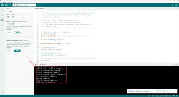
Install Dependency Library
This demo should be used with the Pico PIO USB library, the specific installation steps are shown below:
- Install Pico PIO USB library
- Select "Install All"
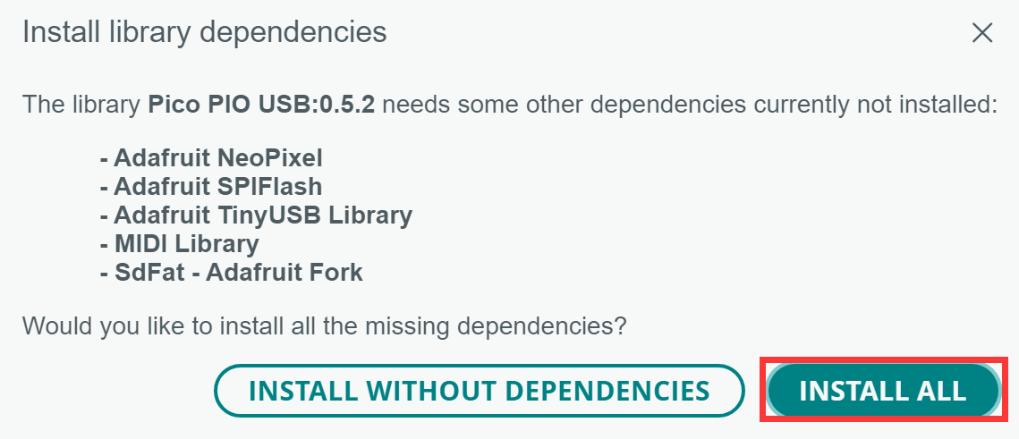
- Installation successful
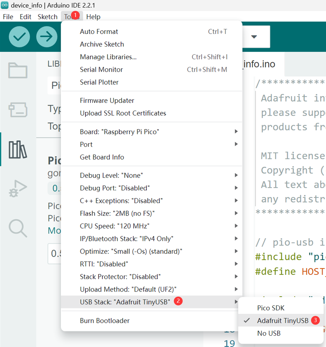
- Change USB Stack configuration
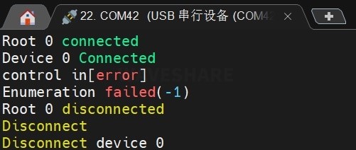
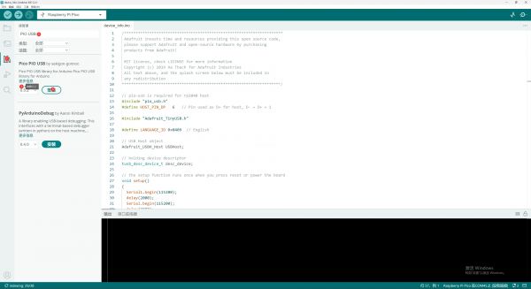
device_info Demo Description
- device_info demo is located in the device_info directory
- PIO-USB will serve as a USB host for receiving and printing descriptor information of USB devices
- After successfully uploading the program, open the serial monitor, connect the USB device, and press the "RUN" button to restart the RP2350-PiZero
Core1 setup to run TinyUSB host with pio-usb
Device attached, address = 1
Device 1: ID 05ac:0256
Device Descriptor:
  bLength             18
  bDescriptorType     1
  bcdUSB              0110
  bDeviceClass        0
  bDeviceSubClass     0
  bDeviceProtocol     0
  bMaxPacketSize0     64
  idVendor            0x05ac
  idProduct           0x0256
  bcdDevice           0310
  iManufacturer       1     CX
  iProduct            2     2.4G Wireless Receiver
  iSerialNumber       0
  bNumConfigurations  1
TinyUSB Dual Device Info Example
03-MicroSD
Demo Description
- Insert TF card, run the demo, and enable writing data to the TF card
Hello, world!
V2-Version Card
R3/R7: 0x1aa
R3/R7: 0x40ff8000
R3/R7: 0xc0ff8000
Card Initialized: High Capacity Card
SD card initialized
SDHC/SDXC Card: hc_c_size: 30475
Sectors: 31207424
Capacity:    15238 MB
Goodbye, world!
Resources
Supporting Resources
Demo
Schematic Diagram
Official Resources
Raspberry Pi Official Documents
- Get Started with MicroPython on Raspberry Pi Pico
- Raspberry Pi related books download
- Pico2 Schematic diagram
- Pico2 Pinout definition
- Pico2 Getting Started
- Pico2 C SDK User Manual
- Pico2 Python SDK User Manual
- Pico2 Datasheet
- RP2350 Datasheet
- RP2350 Hardware Design Reference Manual
Raspberry Pi Open Source Demos
Development Softwares
- Thonny Python IDE (Windows version V3.3.3)
- Pico environment building related software
- pico-vscode package
- Zimo221 Chinese character conversion software
- Image2Lcd image bitmap conversion software
- Font library conversion tutorial
- Image bitmap conversion tutorial
FAQ
You can refer to the RP2350-E9 section in the RP2350 Datasheet
Support
Monday-Friday (9:30-6:30) Saturday (9:30-5:30)
Email: services01@spotpear.com

[Tutorial Navigation]
- Overview
- Introduction
- Features
- Dimensions
- Pico Getting Started
- Firmware Download
- Basic Introduction
- MicroPython Series
- C/C++ Series
- Install VSCode
- Install Extension
- Configure Extension
- New Project
- Compile Project
- Flash Firmware
- Import Project
- Update Extension
- Arduino IDE Series
- Install Arduino IDE
- Arduino IDE Interface
- Install Arduino-Pico Core in Arduino IDE
- Upload Demo at the First Time
- Open Source Demos
- Demo
- C Demo
- 01-DVI
- 02-USB
- Main Directory Analysis
- capture_hid_report Demo Description
- usb_device Demo
- Host_hid_to_device_cdc Demo
- 03-MicroSD
- Arduino Demo
- Resources
- FAQ
- Support