



- sales/support
Google Chat:---
- sales
+86-0755-88291180
- sales01
sales@spotpear.com
- sales02
dragon_manager@163.com
- support
tech-support@spotpear.com
- CEO-Complaints
zhoujie@spotpear.com
- Only Tech-Support
WhatsApp:13246739196
- Purchase/Shipping/Refund
WhatsApp:13424403025
- HOME
- >
- ARTICLES
- >
- For Arduino
- >
- Mother Board
RA4M1-MINI User Guide
Overview
Introduction
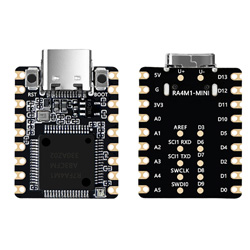
RA4M1-Zero is a compact microcontroller development board with multiple digital interfaces. In terms of hardware, it uses a R7FA4M1AB3CFM chip, which is equipped with a Cortex-M4® 32-bit single-core processor, equipped with an FPU floating point unit, supports up to 48MHz clock frequency, and has a built-in 256KB ROM, 32KB SRAM and 8KB EEPROM. It is compatible with a variety of peripherals and makes it more convenient to use. As for the software, you can choose Arduino IED for development, making it easy and quick to get started and apply it to products.
Features
- Features Renesas RA4M1 MCU, based on the 32-bit ARM Cortex-M4 architecture, with a running frequency of 48MHz and built-in FPU (Floating Point Unit)
- Integrates 256KB flash memory, 32KB SRAM, and 8KB EEPROM
- Equipped with 14-bit ADC, 12-bit DAC, CAN bus controller, USB 2.0 interface, and onboard RGB LED
- Supports firmware encryption, secure boot and anti-tamper functions to improve the security of data and systems and ensure the security of applications
- Provides rich peripheral interfaces, with strong compatibility and expandability
- Castellated module allows soldering directly to carrier boards
- Compatible with Arduino IDE, supports users in quick development and convenient debugging, reducing development difficulty
Onboard Resources


Pinout Definition

Dimensions

Arduino Environment Setup
- Get Arduino IDE from the official website and select the ZIP file to download (for other system users, select the corresponding file to download)

- Download and extract the files, then open the extracted directory, double-click on Arduino IDE.exe, and download the board file needed for RA4M1-Zero

- After the download is completed, reopen Arduino IDE, create a new project --> Flash program --> Observe serial port

- If you see that the serial port outputs Hello, World every 1s, it means that the environment is successfully set up

Bootloader Firmware Download
- Download the corresponding Firmware Flashing Tool, after downloading and extracting successfully, enter the Renesas_Flash directory and double-click the exe file to install, and the installation process options remain the default

- After successful installation, go to the file in the previous step, enter the directory AWAA, double-click to open the AWAA.rpj tool to set the file

- Select Connect Settings on the toolbar, then press and hold the Boot button on the board, then press Reset button to enter the firmware download mode, and then select the corresponding COM port

- Select Operation from the toolbar, then click Add/Remove Files to add Firmware, and delete other unnecessary firmware

- Finally, click on Start and wait for the firmware download to complete. After the download is complete, unplug and plug in the USB again to power on

Demo
| Demo | Basic Description | Dependency Library |
|---|---|---|
| 01_UART_Test | Basic UART communication demo | - |
| 02_CAN_Read_Test | Basic CAN communication reading demo | - |
| 03_CAN_Write_Test | Basic CAN communication sending demo | - |
- For more RA4M1 demos, please refer to Arduino official RA4M1 demos
01_UART_Test
Demo description
- A simple demo of UART interactive communication.
Hardware connection
- Connect the board to the computer using a USB cable

Code analysis
Serial.begin(115200): Initialize UART baud rate to 115200.Serial.available(): Retrieve data from UART cache.Serial.read(): Read data from UART cache.Serial.print(): Send UART data.
Result demonstration
- The program compilation download is complete, open the serial port monitoring and input Hello, World, and you can see that the monitoring console outputs Hello, World at the same time, as shown in the figure below:

02_CAN_Read_Test
Demo description
- A simple CAN bus data communication demo. If you want to see the actual effect, you need to connect an external CAN transceiver. The RA4M1-Zero only has a CAN controller.
Hardware connection
- Connect the board to the computer using a USB cable (refer to demo 01)
Code analysis
CAN.begin(CanBitRate::BR_500k): Initialize CAN bus baud rate to 500K.CAN.available()': Retrieve data from CAN cache.CAN.read(): Read data from CAN cache.
Code analysis
- To see the actual operation effect, the customer needs to connect an external CAN transceiver, and the demo has passed the test normally.
03_CAN_Write_Test
Demo description
- A simple CAN bus sending data communication demo. If you want to see the actual effect, you need to connect an external CAN transceiver. The RA4M1-Zero only has a CAN controller.
Hardware connection
- Connect the board to the computer using a USB cable (refer to demo 01)
Code analysis
CAN.begin(CanBitRate::BR_500k): Initialize CAN bus baud rate to 500K.CAN.write: Send CAN data.
Code analysis
- To see the actual operation effect, the customer needs to connect an external CAN transceiver, and the demo has passed the test normally.
Resources
Software
Programming Software
Firmware Flashing Tool
Firmware
Schematic Diagram
Demo
Demo
Structure File
Datasheets
RA4M1
FAQ
It may be a firmware issue. Press and hold Boot, then press Reset to enter firmware download mode and re-flash the firmware.