- sales/support
Google Chat:---
- sales
+86-0755-88291180
- sales01
sales@spotpear.com
- sales02
dragon_manager@163.com
- support
tech-support@spotpear.com
- CEO-Complaints
zhoujie@spotpear.com
- Only Tech-Support
WhatsApp:13246739196
- Purchase/Shipping/Refund
WhatsApp:13424403025
- HOME
- >
- ARTICLES
- >
- Common Moudle
- >
- Other Acc
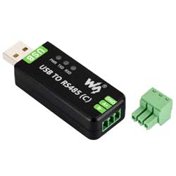
USB TO RS485 (C) User Guide
Features
- USB‑to‑RS485 communication with hardware‑automatic data direction control
- FT232RNL chip for good compatibility, stable, and reliable communication
- Onboard isolated transceiver integrating electrical isolation and ESD protection
- RS485 interface with surge, lightning, and ESD protection
- Onboard resettable fuse and protection diodes for enhanced overcurrent, overvoltage, and transient protection
- Onboard PWR, TXD, RXD LEDs for easy monitoring of power and data status
- Supports Windows, Linux, Mac, Android, WinCE, and other operating systems
Specifications
| Parameter | Description |
|---|---|
| Product Type | Industrial‑grade isolated USB to RS485 converter |
| Host Interface | USB |
| Device Interface | RS485 |
| USB Connector Type | USB-A |
| USB Operating Voltage | 5 V |
| Communication Chip | FT232RNL |
| Data Rate | 300 bps ~ 512000 bps |
| RS485 Pins | A+, B‑, GND |
| RS485 Connector Type | Screw terminal |
| Direction Control | Hardware automatically controls data direction |
| RS485 Nodes | Point‑to‑multipoint, up to 32 nodes; more than 16 nodes recommend using a repeater |
| RS485 Transmission Distance | Approximately 1200 m at low baud rates |
| USB Transmission Distance | Approximately 5 m |
| RS485 Termination | Onboard 120 Ω balancing resistor |
| Interface Protection | 600 W surge/lightning protection, 15 kV ESD protection |
| Isolation Method | Optical isolation |
| Isolation Voltage | Up to 2.5 kV |
| Operating Temperature | -40℃ ~ 85℃ |
| Operating Humidity | 5%RH ~ 95%RH |
| Supported Operating Systems | Windows 11 / 10 / 8.1 / 8 / 7 / XP, Mac, Linux, Android, WinCE |
LED Indicator Descriptions
| LED Indicator | Status Description |
|---|---|
| PWR | Power indicator, lights when USB is connected and voltage is detected |
| TXD | Transmit indicator, lights when data is being sent from the USB port |
| RXD | Receive indicator, lights when data is returned from the RS485 device side |
Interface Description
| Interface | Description |
|---|---|
| USB‑A | Connects to host devices such as PC, industrial computer, Raspberry Pi, Jetson |
| A+ | RS485 differential signal A |
| B‑ | RS485 differential signal B |
| GND | RS485 side reference ground; recommended for long‑distance or multi‑node communication |
The USB TO RS485 (C) employs an isolated design. The isolation circuitry reduces ground loops and common‑mode interference between the USB host side and the RS485 bus side. The GND on the RS485 side is used as a bus reference ground and for noise immunity; it is not equivalent to directly shorting the field device ground to the computer USB ground.
Isolation and Protection
Isolated RS485 converters are suitable for scenarios where there are significant ground potential differences, many interference sources, long transmission distances, or many bus nodes. The isolation and protection design of the USB TO RS485 (C) includes:
- Optical isolation: reduces interference coupling between the USB host side and the RS485 field side
- TVS protection: suppresses surge voltages and transient spikes
- ESD protection: improves electrostatic discharge immunity during plugging/unplugging, wiring, and on‑site operation
- Resettable fuse: automatically recovers after an overcurrent fault, reducing maintenance costs compared to one‑time fuses
- 120 Ω termination: helps reduce signal reflections in long‑distance or high‑speed communication
User Guide
Driver Installation
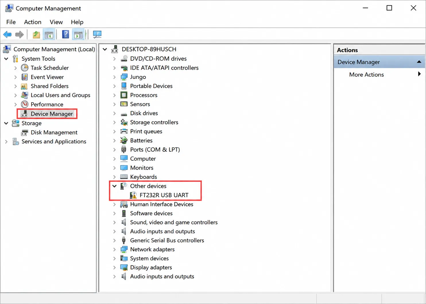
The USB TO RS485 (C) uses the FT232RNL chip. Most systems will automatically recognize it as a virtual COM port. If no available COM port appears in Device Manager, or if the serial device shows a yellow exclamation mark, manually install the FTDI VCP driver.
Manual Installation on Windows
Method 1: Download Driver Genius from the Internet and let it automatically detect and install the driver.
Method 2: Install the driver manually (the following uses Windows 7 as an example).
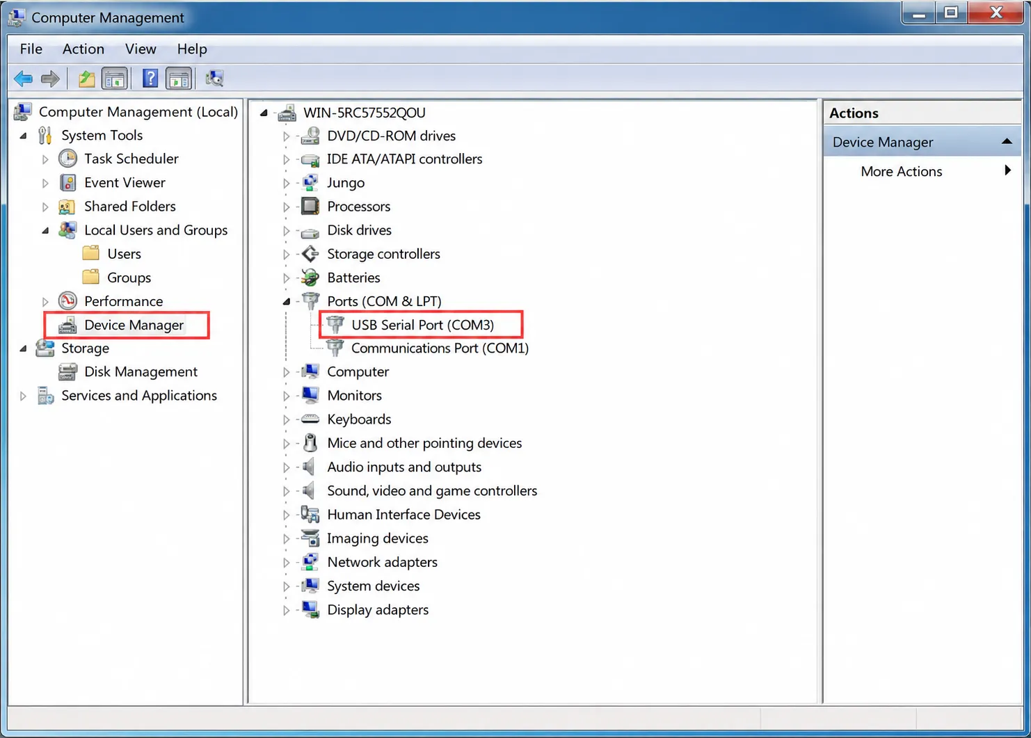
Connect the device to the computer via USB. In Device Manager, if the COM port has a yellow exclamation mark, the driver is not installed.
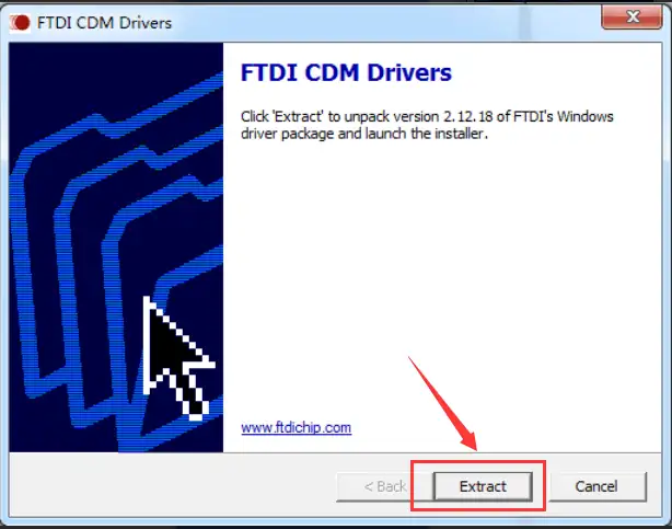
Download the software package from the official wiki. Double‑click the application and click Extract:
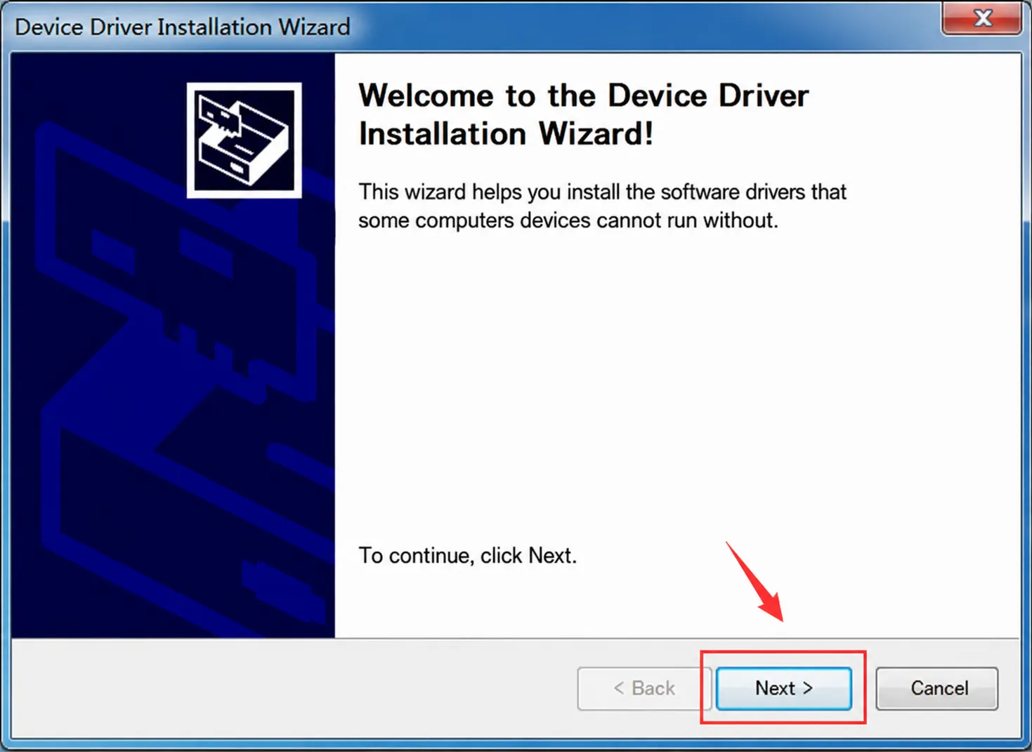
Click Next:
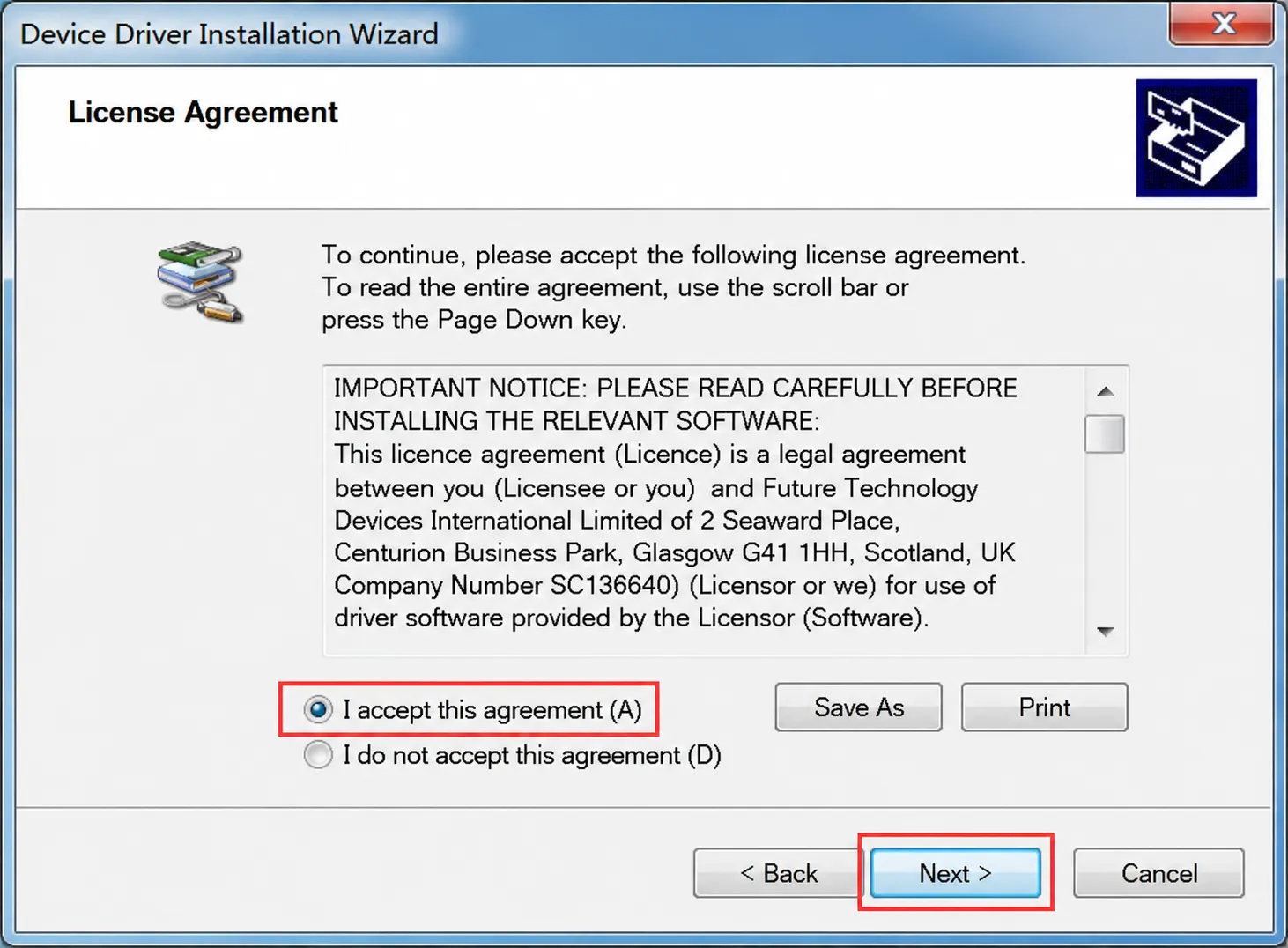
Check "I accept this agreement", then click Next:
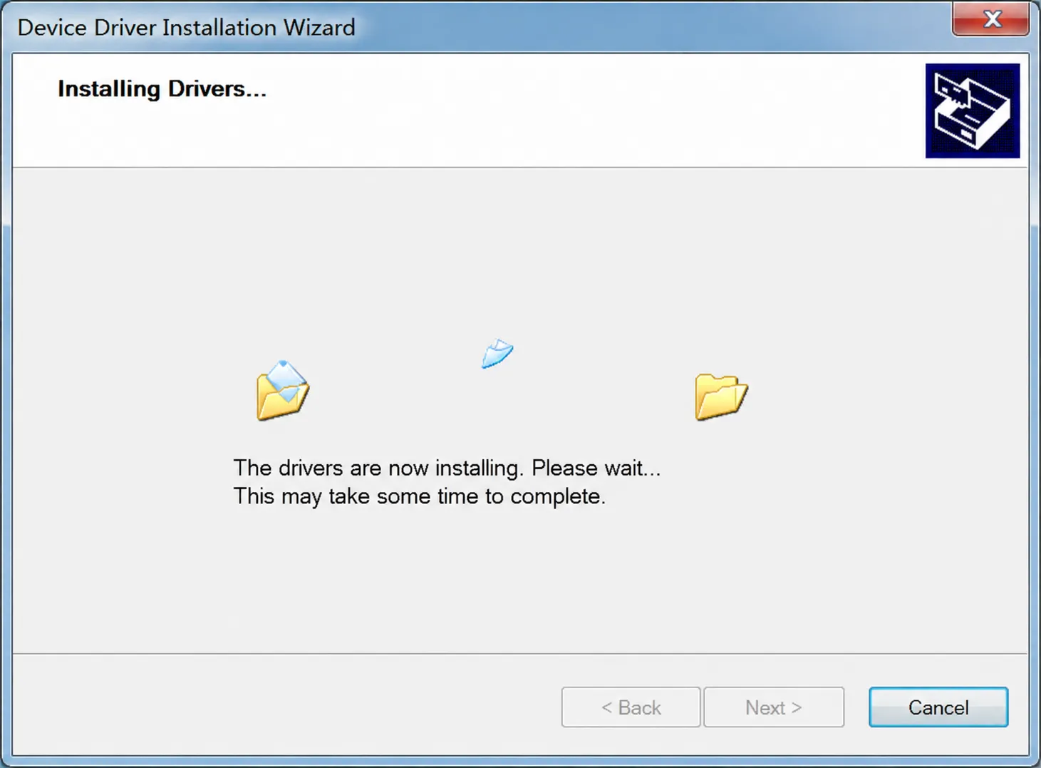
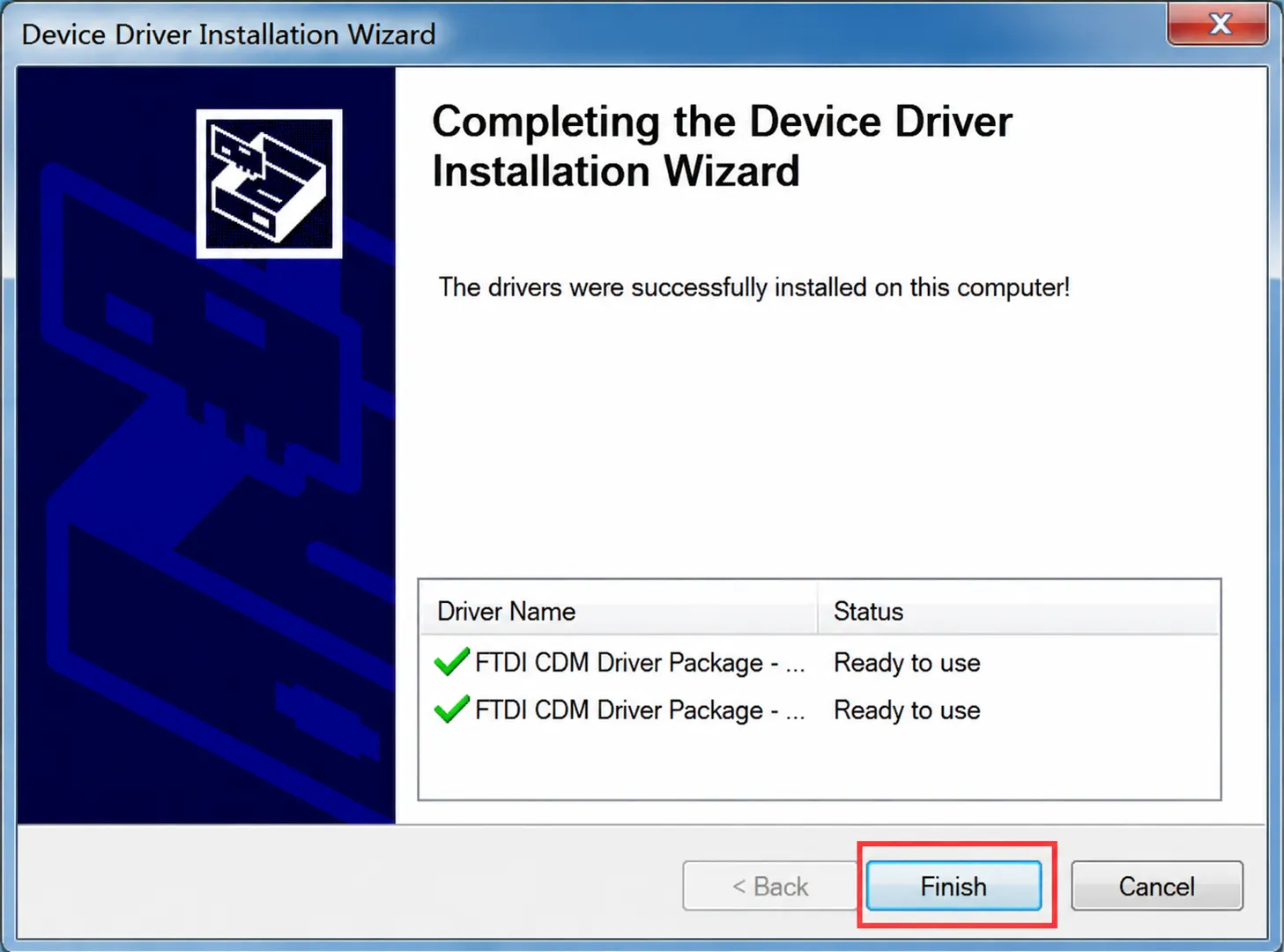
Wait for the installation to complete, then click Finish:
Now check Device Manager; the COM port should be available for normal use.
RS485 Wiring
Connect the USB TO RS485 (C) to the target RS485 device:
| USB TO RS485 (C) | Target RS485 Device |
|---|---|
| A+ | A / 485+ |
| B- | B / 485- |
| GND | GND (connect as needed) |
For short distances and low‑interference environments, only A+ and B‑ may be sufficient for communication. For long‑distance, multi‑node, or high‑interference environments, it is recommended to connect GND as a reference ground and to use appropriate termination resistors based on the bus topology.
RS485 Communication Test
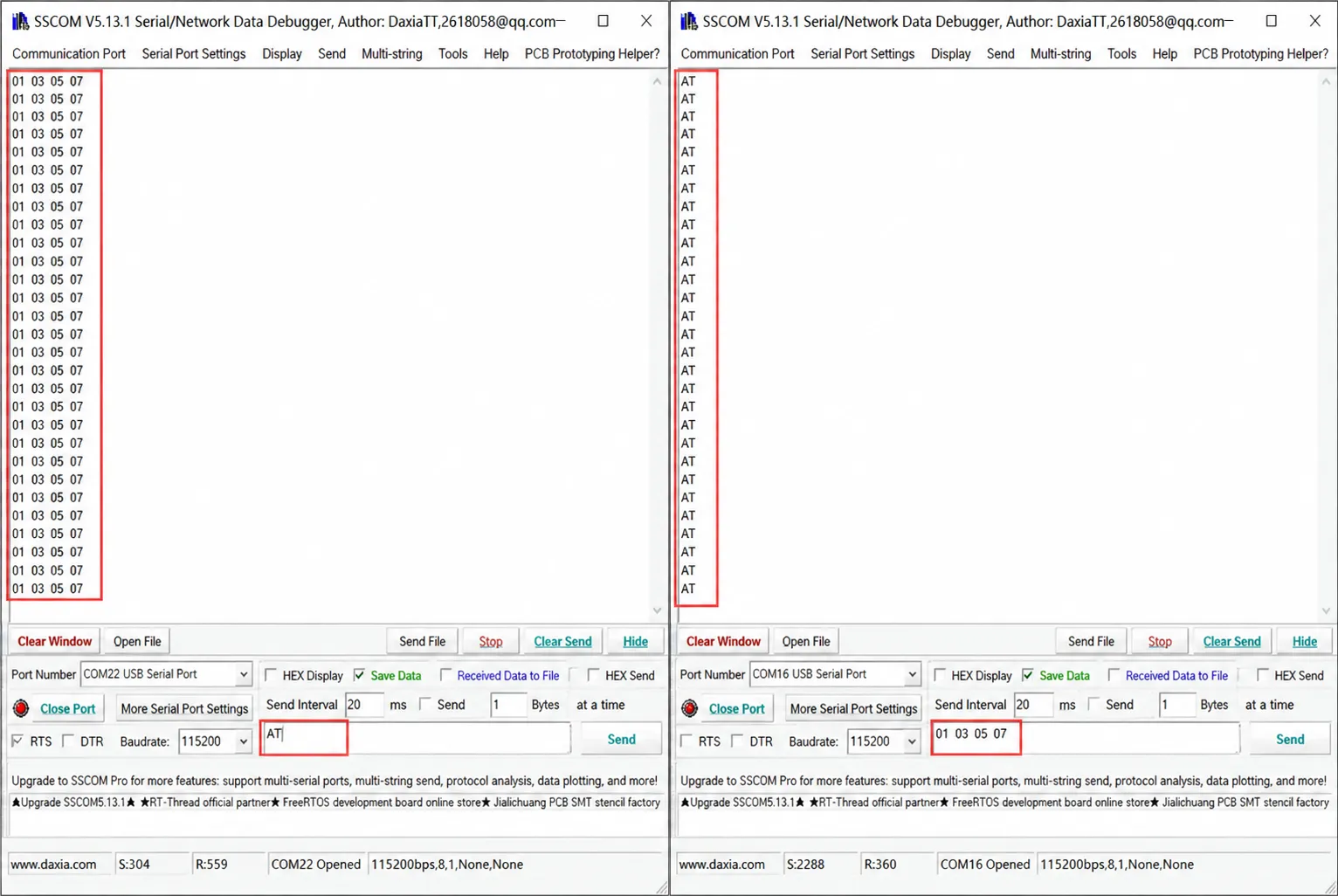
You can interconnect two USB TO RS485 converters or connect to a target RS485 device for testing.
- Connect A+ to A+, B‑ to B‑, and GND if necessary.
- On the computer, open a serial debug assistant such as SSCOM.
- Select the appropriate COM port and set the same baud rate, data bits, parity, and stop bits.
- Send test data and observe the TXD/RXD LEDs and the receive window.
- If communication fails, try swapping A+ / B‑, lowering the baud rate, checking termination resistors, and inspecting cable shielding and grounding.
Modbus Device Communication
The USB TO RS485 (C) is a physical‑layer interface converter; it does not have a built‑in Modbus master or slave protocol stack. When connecting to Modbus RTU devices, the Modbus protocol must be implemented on the PC, industrial computer, single‑board computer, or host software, and then the module is used to send and receive RS485 data.
Typical test procedure:
- Connect A / B / GND to the Modbus RTU device.
- Confirm the slave address, baud rate, parity, data bits, and stop bits.
- Use Modbus Poll, a serial debug assistant, or a custom host program to send Modbus RTU commands.
- Refer to the slave device protocol manual to confirm register addresses, function codes, and data formats.
Precautions for Isolated Applications
- The isolated design reduces interference coupling between the host side and the field side, but does not replace proper field grounding, shielding, and lightning protection.
- Twisted‑pair cable is recommended for the RS485 bus. Shielded twisted‑pair cable is recommended for long‑distance wiring.
- 120 Ω termination resistors can be installed at both ends of the bus depending on communication distance and speed. If short‑distance communication is abnormal, try removing termination.
- For multi‑node communication, a daisy‑chain topology is recommended; avoid long star‑type branches. When wiring near interference sources such as high-voltage equipment, frequency converters, and motors, increase separation distance or adopt shielding, grounding, and lightning protection measures.
Resources
1. Software
- VCP Driver:
- Serial Debug Tools:
2. Datasheets
Support
Monday-Friday (9:30-6:30) Saturday (9:30-5:30)
Email: services01@spotpear.com