- sales/support
Google Chat:---
- sales
+86-0755-88291180
- sales01
sales@spotpear.com
- sales02
dragon_manager@163.com
- support
tech-support@spotpear.com
- CEO-Complaints
zhoujie@spotpear.com
- sales/support
WhatsApp:13246739196
- HOME
- >
- ARTICLES
- >
- Common Moudle
- >
- UART Module
USB TO 4CH RS485 (B) User Guide
Overview
Introduction
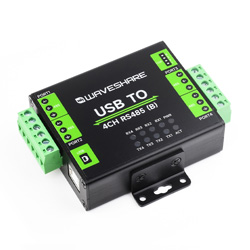
USB TO 4CH RS485 (B) is an industrial USB to RS485 converter, adopting original CH344L, with protection circuits such as built-in power isolation, ADI magnetical isolation, and TVS, aluminum alloy case design. USB TO 4CH RS485 (B) is easy to operate, automatic transmit, featuring fast communication, stability, reliability, and safety, suitable for industrial devices and applications with high requirements.
Features
- Adopts original CH344L chip, high-speed communication, stable and reliable, better compatibility.
- Supports USB to 4-ch isolated RS485, convenient for expanding multiple RS485 industrial serial devices.
- Onboard unibody power isolation, provides stable isolation voltage, no additional power supply is required at the isolated side.
- Onboard unibody digital isolation, support signal isolation, with better reliability, stronger anti-interference ability, and lower power consumption.
- Onboard TVS (Transient Voltage Suppressor) to effectively suppress surge voltage and transient spike voltage in circuits, lightning-proof protection, and anti-static protection.
- Onboard self-resetting fuses and protection diodes ensure stable current and voltage output, prevent overcurrent and overvoltage, and improve shock resistance.
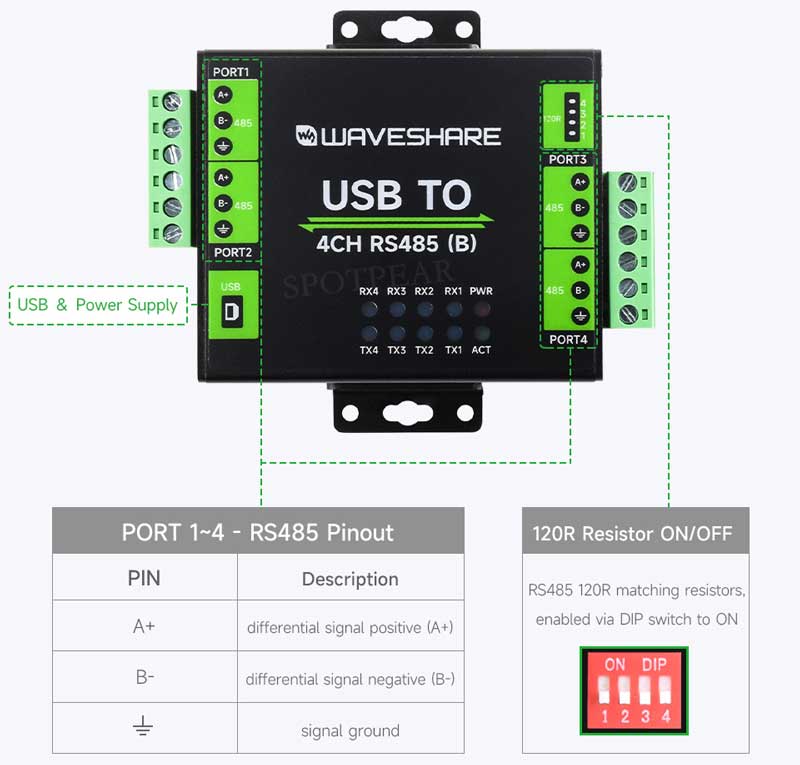
- Built-in RS485 output terminal 120R, can be enabled by dip switches, and flexible switching.
- 10x external LEDs for power, device configuration status, and signaling status.
- Industrial grade metal case, support wall-mount, and rail-mount installation, rigid and nice-looking, easy to install.
Parameters
| Product Types | Industrial grade isolated USB to RS485 converter | |
| Host Interface | USB | |
| Device Interface | RS485 | |
| Communication Range | 1200bps ~ 460800bps | |
| USB | Operation Level | 5V |
| Interface | USB-B Connector | |
| Interface Protection | 500mA self-recovery fuse, isolated output | |
| RS485 | Interface | Screw Terminal |
| Direction Control | Hardware automatic control | |
| Interface Protection | Provide 600W lightning proof, anti-surge and 15KV ESD protection (onboard 120R balancing resistor) | |
| Transmission Mode | Peer-to-Multiple (up to 32 nodes, repeaters recommended for more than 16 nodes) | |
| Indicator | PWR | Power indicator, connect to USB, Red LED lights on when detecting the voltage |
| ACT | Green status indicator, lights on when detecting the driver | |
| RXD | RX indicator, lights on when receiving data from the corresponding port | |
| TXD | TX indicator, lights on when sending data from the corresponding port | |
| Usage Environment | Temperature Range | -40℃ ~ 85℃ |
| Humidity Range | 5% ~ 95%RH | |
| OS | Mac, Linux, Android, Windows 11 / 10 / 8.1 / 8 / 7 | |
Interface Introduction
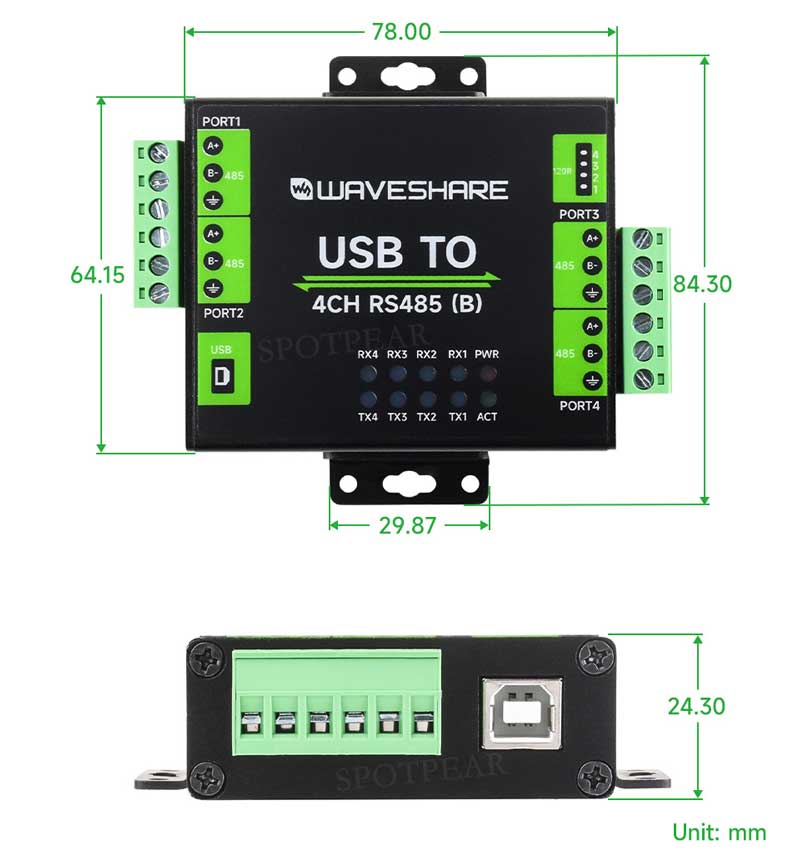
Dimensions
Driver Installation
CDC Driver
The default driver of the computer is CDC driver, and you can view it from the device manager.
VCP Driver
The VCP driver is the default driver demo from the manufacturer, which needs to be installed by yourself, and you can view it from the device manager.
Linux/RPI
Take RPI as an example, you can use the default driver. After connecting the device, run the following command to query the name of the serial device:
ls /dev/tty*

For example, use minicom to open UART, enter the following command
minicom -D /dev/ttyACM0
RS485 Communication
Hardware Connection
- If you want to connect it with the Port, you can refer to the following: the communication between Port A and Port B.
| USB TO 4CH RS485 (B) - PORT A | USB TO 4CH RS485 (B) - PORT B |
| PORT A - GND | PORT B - GND |
| PORT A - A+ | PORT B - A+ |
| PORT A - B- | PORT B - B- |
Software Operation
- Open two SSCOM windows.
- Respectively select the corresponding COM port of the Port A and Port B.
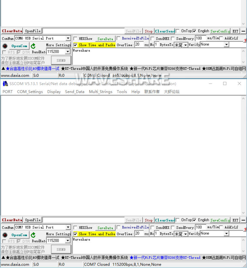
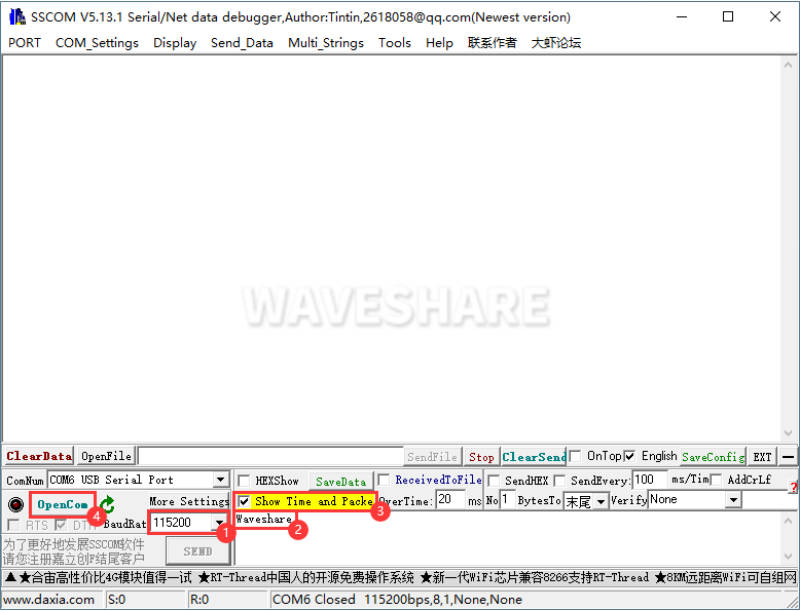
- Select the baud rate as 115200, input the characters you need to send, select Show Time and Packet for better effect, and click Open COM.
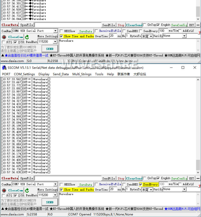
- Select 100ms interval of one of the SSCOMs, you can see that the two Port ports are sending and receiving normally, and the test result is shown in the figure below:
Resource
Datasheet
Software and Driver
FAQ
Question:After installing the driver in the WIN7 environment, it shows that the digital signature of this device cannot be verified.
This is a Microsoft bug, click to download the driver repair tool and install it.
Question:Can you explain to me how to install a DIN rail bracket?
The rails and ears share screw holes. Please remove the wall mounting ears and install the DIN rail bracket as shown: 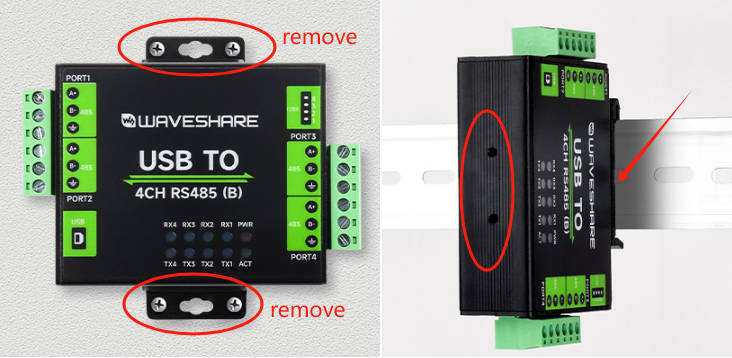
Question:What are the parameters of the screw holes and distance?
Please note that the rail and mounting ear share the same screw hole. Before installing the DIN rail, you need to remove the mounting ear. As shown below: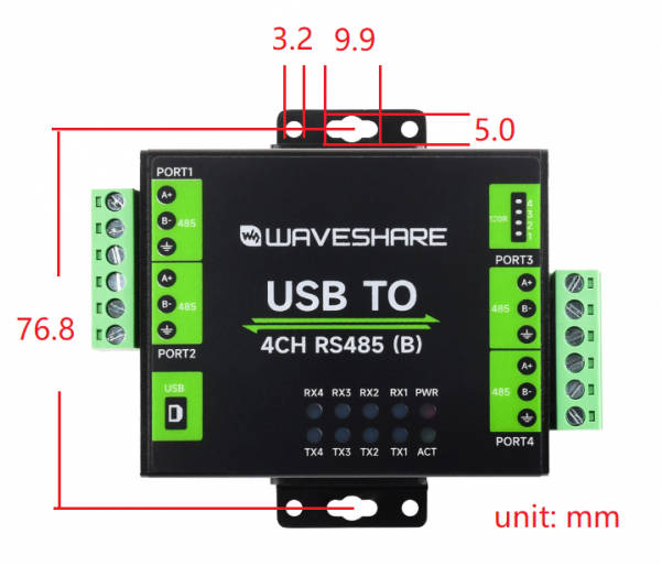
Question:Is there all 4 RS485 channels isolated from each other, or if they all share the same ground?
The USB and four RS485 interfaces are isolated, but there is no isolation between the four RS485 interfaces; that is, when the high voltage on the RS485 side is damaged, the USB side will be protected, but the RS485 side will not be protected.
Support
Monday-Friday (9:30-6:30) Saturday (9:30-5:30)
Email: services01@spotpear.com
[Tutorial Navigation]
- Overview
- Driver Installation
- RS485 Communication
- Resource
- FAQ
- Question:After installing the driver in the WIN7 environment, it shows that the digital signature of this device cannot be verified.
- Question:Can you explain to me how to install a DIN rail bracket?
- Question:What are the parameters of the screw holes and distance?
- Question:Is there all 4 RS485 channels isolated from each other, or if they all share the same ground?
- Support


