




- sales/support
Google Chat:---
- sales
+86-0755-88291180
- sales01
sales@spotpear.com
- sales02
dragon_manager@163.com
- support
tech-support@spotpear.com
- CEO-Complaints
zhoujie@spotpear.com
- Only Tech-Support
WhatsApp:13246739196
- Purchase/Shipping/Refund
WhatsApp:13424403025
- HOME
- >
- ARTICLES
- >
- Common Moudle
- >
- Power
Modbus RTU PWM Output 4CH User Guide
Features
- Output uses high-speed opto-isolation; output high-level voltage can be selected via internal jumper
- Four independent PWM pulse outputs with adjustable frequency and duty cycle
- Supports setting device address (1 ~ 255) for cascading multiple devices via RS485 bus
- Onboard voltage regulator chip supports wide 7 V ~ 36 V power supply
- Onboard integrated isolated power supply provides stable isolated voltage; the isolated side requires no additional power
- Onboard integrated magnetic coupling isolation provides signal isolation, ensuring high reliability and strong anti-interference capability
- Onboard resettable fuse and TVS (transient voltage suppression) diode effectively suppress surge voltage and transient spike voltage in the circuit, providing overcurrent, overvoltage, lightning, and electrostatic protection
- Built-in watchdog timer ensures stable operation without freezing
- Rail-mounted enclosure design, compact size, easy installation
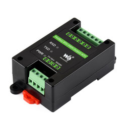
- Three external LED indicators for easy monitoring of power status and signal transmission/reception
Product Parameters
| Communication Interface | RS485 |
|---|---|
| Communication Baud Rate | 4800, 9600, 19200, 38400, 57600, 115200, 128000, 256000 |
| Default Communication Format | 9600, N, 8, 1 |
| Modbus Protocol | Standard Modbus RTU protocol |
| Supply Voltage | DC 7~36 V |
| Output Voltage | 3.3 V or 5 V selectable |
| Output Current | <30mA, signal type |
| Pulse Frequency | 1 Hz~200 kHz |
| Pulse Resolution | 0.01 Hz |
| Pulse Accuracy | 5‰ |
| Duty Cycle | 0~100% |
| Duty Cycle Resolution | 0.01% |
| Duty Cycle Accuracy | 5‰(1 Hz~50 kHz), 1%(50 kHz~200 kHz) |
Indicator Light Description
| Indicator | Status Description |
|---|---|
| PWR LED | Power indicator, flashes when MCU is working normally |
| TXD LED | Transmission indicator, lights up when transmitting data |
| RXD LED | Reception indicator, lights up when receiving data |
Hardware Interface Description
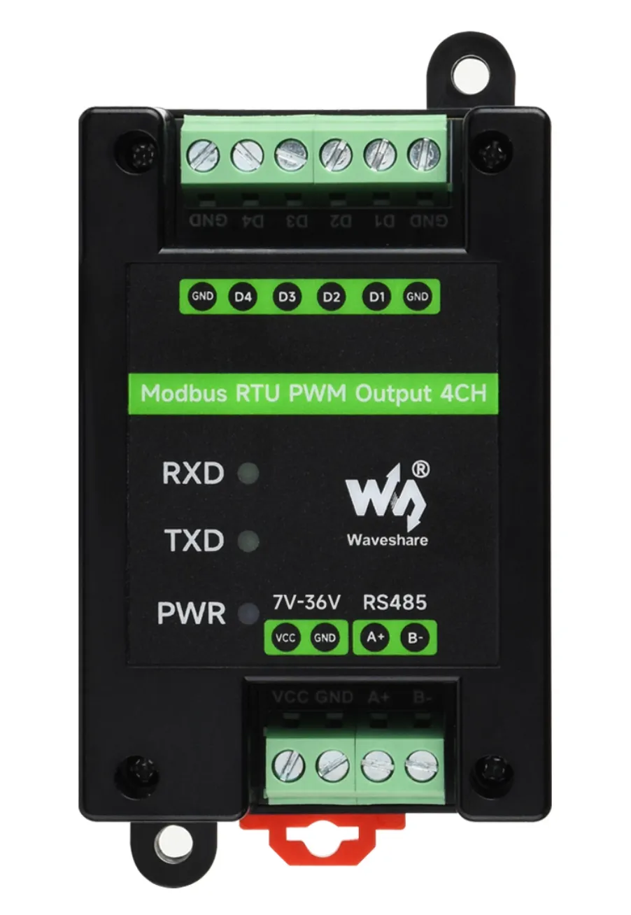
D1~D4 are pulse output terminals, GND is power ground. The PWM output frequency range is 1 Hz~200 kHz.
Hardware Connection Description
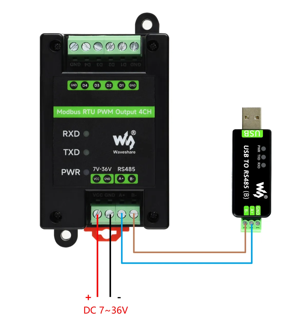
Connect the USB TO 485 converter to the target board using jumper wires, connecting A-->A and B-->B as shown in the figure below:
Software Test
SSCOM Serial Debug Assistant
Basic Query Commands
Download the SSCOM Serial Debug Assistant and open it on your computer. Open the corresponding port number, set the baud rate to 9600, select SendHex and Receive, and choose ModbusCRC16 check for the checksum.
Send the following command. Under normal conditions, channel 1 will output a pulse with a frequency of 1 kHz and a duty cycle of 50%.
01 10 00 00 00 03 06 00 01 86 A0 13 88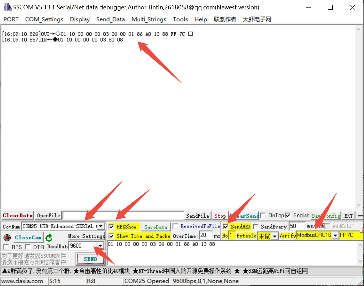
Other Commands
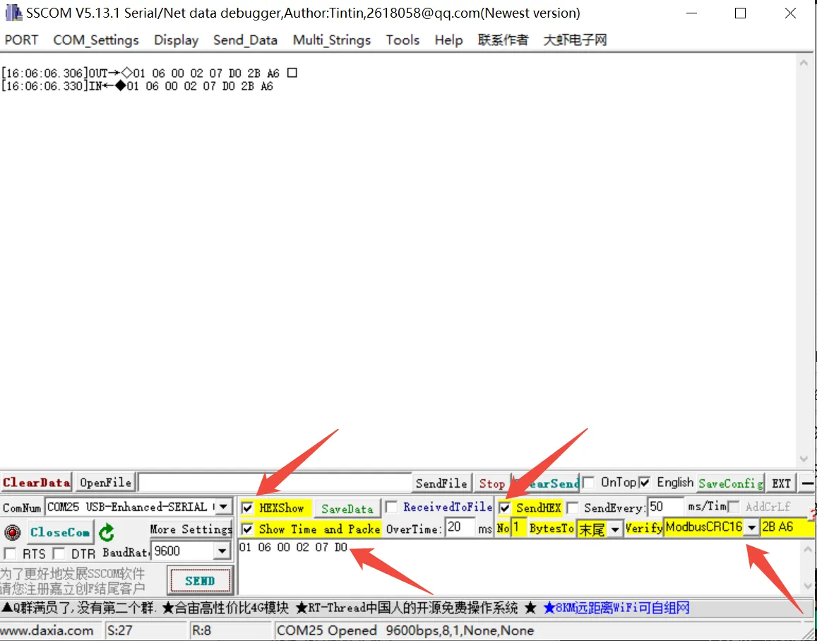
- If you need to send other commands, select SendHEX, choose ModbusCRC16 check for the checksum, enter the first six bytes of the command, and click SEND, it will automatically add the CRC check code. For example, sending the following command sets channel 1 duty cycle to 20%.01 06 00 02 07 D0
For more detailed control commands, please refer to the development protocol.
Modbus Poll Software
The serial software is not convenient for data observation. You can use the Modbus Poll Software to read data. Download and install the Modbus Poll software.
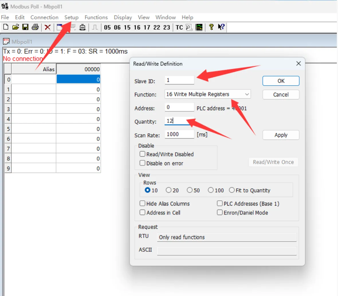
Open the software, select Setup -> Read/Write Definition. Set Slave ID to the actual device address, select Function 16, change Quantity to 12 channels. Click OK to confirm.
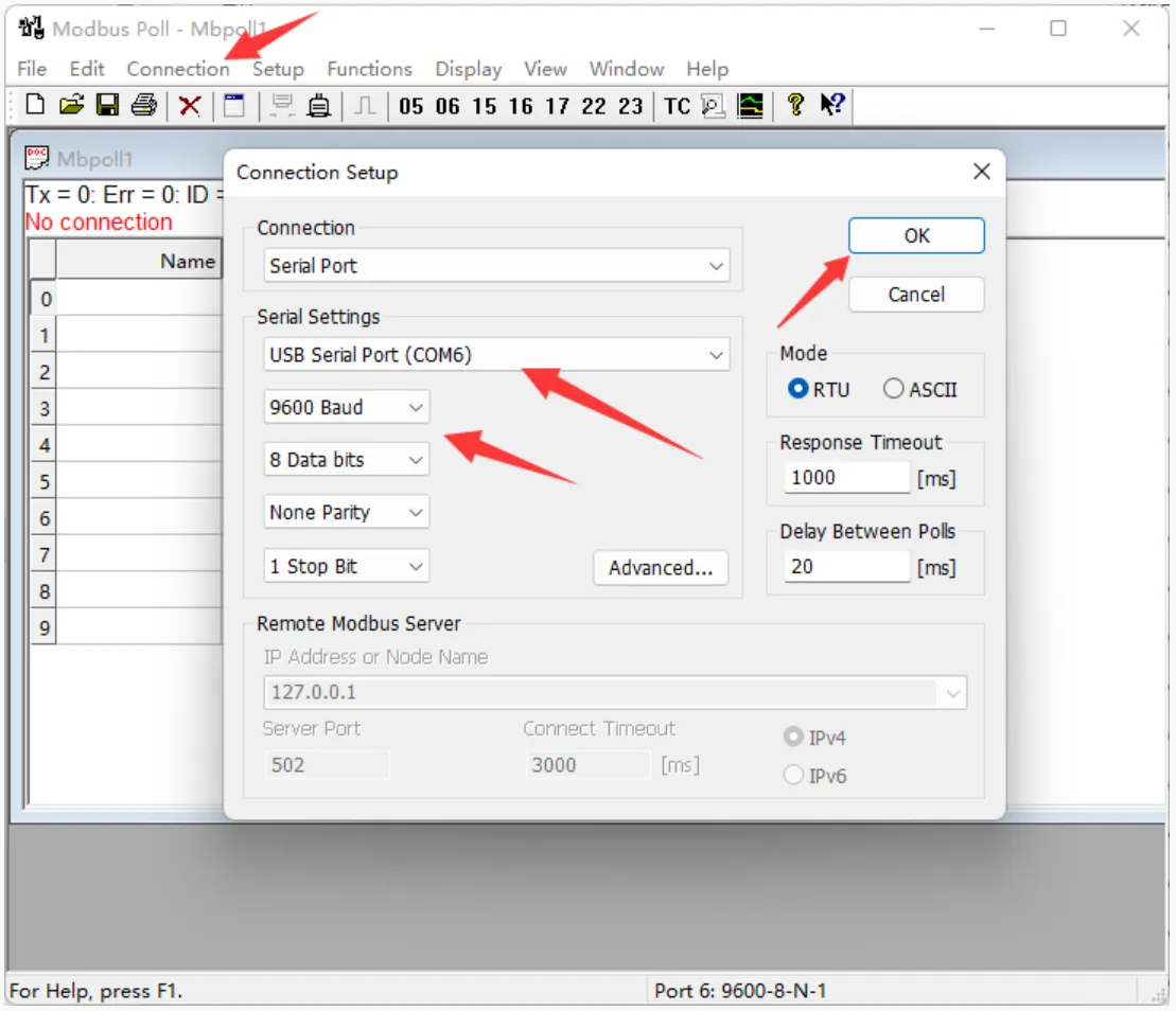
Select Connection -> Connect..., choose the corresponding serial port, set baud rate to 9600, 8 data bits, no parity, 1 stop bit. Click OK to connect.
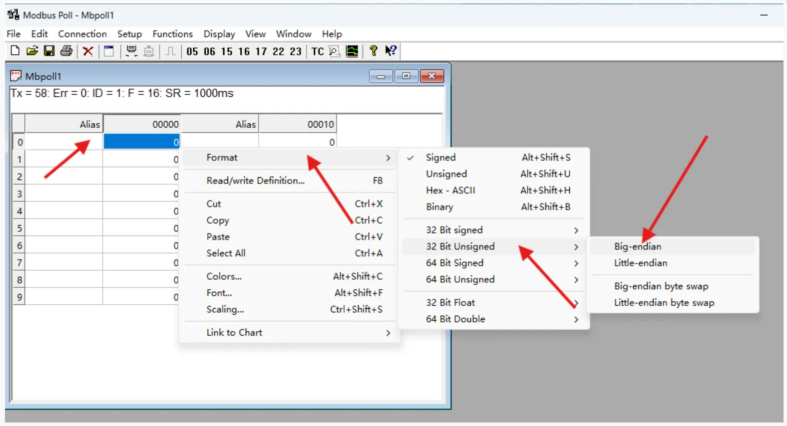
After successful connection, set the frequency format. Select registers 0, 3, 6, 9 and set their format to Unsigned 32-bit Big-endian. You can also add register notes in the Alias column.
Enter the channel frequency and duty cycle in the registers; the corresponding pulse will be output. Frequency range: 100
100000000, i.e., 1 Hz200 kHz. Duty cycle range: 010000, i.e., 0100%. The figure below shows the settings: Channel 1: 500 Hz, 10%; Channel 2: 1 kHz, 30%; Channel 3: 5 kHz, 50%; Channel 4: 10 kHz, 90%.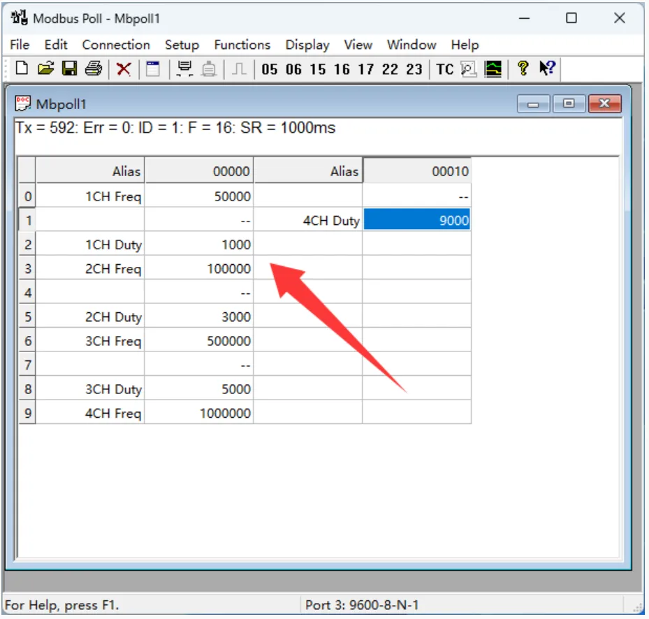
Secondary Development Protocol
Function Code Introduction
| Function Code | Description |
|---|---|
| 03 | Read Holding Registers |
| 06 | Write Single Holding Register |
| 10 | Write Multiple Holding Registers |
Register Address Description
| Address (HEX) | Address Storage Content | Register Value | Access | Modbus Function Code |
|---|---|---|---|---|
| 4x0000 4x0001 | Channel 1 Frequency High 16-bit Channel 1 Frequency Low 16-bit | Value is unsigned 32-bit hexadecimal, unit 0.01 Hz, range: 100~20000000, i.e., 1 Hz~200 kHz | Read/Write | 0x03,0x06,0x10 |
| 4x0002 | Channel 1 Duty Cycle | Value is unsigned 16-bit hexadecimal, unit 0.01%, range 0~1000, i.e., 0~100% | Read/Write | 0x03,0x06,0x10 |
| 4x0003 4x0004 | Channel 2 Frequency High 16-bit Channel 2 Frequency Low 16-bit | Value is unsigned 32-bit hexadecimal, unit 0.01 Hz, range: 100~20000000, i.e., 1 Hz~200 kHz | Read/Write | 0x03,0x06,0x10 |
| 4x0005 | Channel 2 Duty Cycle | Value is unsigned 16-bit hexadecimal, unit 0.01%, range 0~1000, i.e., 0~100% | Read/Write | 0x03,0x06,0x10 |
| 4x0006 4x0007 | Channel 3 Frequency High 16-bit Channel 3 Frequency Low 16-bit | Value is unsigned 32-bit hexadecimal, unit 0.01 Hz, range: 100~20000000, i.e., 1 Hz~200 kHz | Read/Write | 0x03,0x06,0x10 |
| 4x0008 | Channel 3 Duty Cycle | Value is unsigned 16-bit hexadecimal, unit 0.01%, range 0~1000, i.e., 0~100% | Read/Write | 0x03,0x06,0x10 |
| 4x0009 4x000A | Channel 4 Frequency High 16-bit Channel 4 Frequency Low 16-bit | Value is unsigned 32-bit hexadecimal, unit 0.01 Hz, range: 100~20000000, i.e., 1 Hz~200 kHz | Read/Write | 0x03,0x06,0x10 |
| 4x000B | Channel 4 Duty Cycle | Value is unsigned 16-bit hexadecimal, unit 0.01%, range 0~1000, i.e., 0~100% | Read/Write | 0x03,0x06,0x10 |
| 4x2000 | Serial Port Parameters | High byte: parity mode: 0x00~0x02 Low byte: baud rate mode: 0x00~0x07 | Read/Write | 0x03,0x06 |
| 4x4000 | Device Address | Stores Modbus address directly Device address: 0x0001-0x00FF | Read/Write | 0x03,0x06 |
| 4x8000 | Software Version | Convert to decimal, then shift decimal point two places left for version 0x0064 = 100 = V1.00 | Read | 0x03 |
- Note: It is recommended to use function code 10 to set frequency with multiple registers simultaneously. Using function code 06 to operate a single register may output an unknown frequency.
Operation Command Description
Set Channel Output Command
Transmission Code: 01 10 00 00 00 03 06 00 01 86 A0 13 88 FF 7C
| Field | Description | Note |
|---|---|---|
| 01 | Device Address | 0x00 indicates broadcast address; 0x01-0xFF indicate device address |
| 10 | Write Multiple Registers Command | |
| 00 00 | Register Start Address | Channel start register |
| 00 03 | Number of Registers | Number of registers to set |
| 06 | Byte Count | Number of output bytes |
| 00 01 86 A0 13 88 | Register Data Frequency High 16-bit Frequency Low 16-bit Duty Cycle | Frequency is unsigned 32-bit hexadecimal, unit 0.01 Hz, range: 100~20000000, i.e., 1 Hz~200 kHz Duty Cycle is unsigned 16-bit hexadecimal, unit 0.01%, range 0~1000, i.e., 0~100% |
| FF 7C | CRC16 | CRC16 checksum of the first 6 bytes of data |
Return Code: 01 10 00 00 00 03 80 08
| Field | Description | Notes |
|---|---|---|
| 01 | Device Address | 0x00 indicates broadcast address; 0x01-0xFF indicate device address |
| 10 | Write Multiple Registers Command | |
| 00 00 | Register Start Address | 0x0000 - 0x0007 correspond to output channels 1~8 |
| 00 03 | Number of Registers | Number of registers set, cannot exceed maximum channel count |
| 80 08 | CRC16 | CRC16 checksum of the first 6 bytes of data |
Example: Device address 1
Set channel 2 output 200 Hz 10% duty cycle : 01 10 00 00 00 03 06 00 00 4E 20 03 E8 F0 DC
Set channels 1\~4 output 1 kHz 50% duty cycle : 01 10 00 00 00 0C 18 00 01 86 A0 13 88 00 01 86 A0 13 88 00 01 86 A0 13 88 00 01 86 A0 13 88 6E E5
Set Channel Frequency Command
Transmission Code: 01 10 00 00 00 02 04 00 01 86 A0 C0 77
| Field | Description | Notes |
|---|---|---|
| 01 | Device Address | 0x00 indicates broadcast address; 0x01-0xFF indicate device address |
| 10 | Write Multiple Registers Command | |
| 00 00 | Register Start Address | Channel start register, 00 00 indicates channel 1 start register |
| 00 02 | Number of Registers | Number of registers to set, value is unsigned 32-bit hexadecimal, each register is 16-bit |
| 04 | Byte Count | Number of output bytes |
| 00 01 86 A0 | Register Data Frequency High 16-bit Frequency Low 16-bit | Frequency is unsigned 32-bit hexadecimal, unit 0.01 Hz, range: 100~20000000, i.e., 1 Hz~200 kHz |
| C0 77 | CRC16 | CRC16 checksum of the first 6 bytes of data |
Return Code: 01 10 00 00 00 02 41 C8
| Field | Description | Notes |
|---|---|---|
| 01 | Device Address | 0x00 indicates broadcast address; 0x01-0xFF indicate device address |
| 10 | Write Multiple Registers Command | |
| 00 00 | Register Start Address | 0x0000 - 0x0007 correspond to output channels 1~8 |
| 00 02 | Number of Registers | Number of registers set, cannot exceed maximum channel count |
| 41 C8 | CRC16 | CRC16 checksum of the first 6 bytes of data |
Example: Device with address 1
Set channel 2 output 200 Hz : 01 10 00 00 00 02 04 00 00 4E 20 C7 D7
Set Channel Duty Cycle Command
Transmission Code: 01 06 00 02 07 D0 2B A6
| Field | Description | Notes |
|---|---|---|
| 01 | Device Address | 0x00 indicates broadcast address; 0x01-0xFF indicate device address |
| 06 | 06 Command | Write Single Holding Register |
| 00 02 | Register Address | Channel 1 duty cycle register |
| 07 D0 | Register Data | Duty cycle is unsigned 16-bit hexadecimal, unit 0.01%, range 0~1000, i.e., 0~100% |
| 2B A6 | CRC16 | CRC16 checksum of the first 6 bytes of data |
Return Code: 01 06 00 02 07 D0 2B A6
| Field | Description | Notes |
|---|---|---|
| 01 | Device Address | 0x00 indicates broadcast address; 0x01-0xFF indicate device address |
| 06 | 06 Command | Write Single Holding Register |
| 00 02 | Register address | Channel duty cycle register |
| 07 D0 | Register Data | Duty cycle is unsigned 16-bit hexadecimal, unit 0.01%, range 0~1000, i.e., 0~100% |
| 2B A6 | CRC16 | CRC16 checksum of the first 6 bytes of data |
Example: Device with address 1
Set channel 1 duty cycle 20% : 01 06 00 02 07 D0 2B A6
Set channel 2 duty cycle 50% : 01 06 00 05 13 88 94 9D
Set channel 4 duty cycle 20% : 01 06 00 0B 23 28 E1 26
Read Channel Output Command
Transmission Code: 01 03 00 00 00 0C 45 CF
| Field | Description | Notes |
|---|---|---|
| 01 | Device Address | 0x00 indicates broadcast address; 0x01-0xFF indicate device address |
| 03 | 03 Command | Read Holding Registers |
| 00 00 | Register Start Address | 0x0000 - 0x0007 correspond to input channels 1~8 |
| 00 0C | Number of Registers | Number of registers to read, cannot exceed maximum channel count |
| 45 CF | CRC16 | CRC16 checksum of the first 6 bytes of data |
Return Code: 01 03 18 00 01 86 A0 13 88 00 01 86 A0 13 88 00 01 86 A0 13 88 00 01 86 A0 13 88 90 CE
| Field | Description | Notes |
|---|---|---|
| 01 | Device Address | 0x00 indicates broadcast address; 0x01-0xFF indicate device address |
| 03 | 03 Command | Read Holding Registers |
| 18 | Byte Count | Total bytes of returned status information |
| 00 01 86 A0 13 88 …… | Output Values | Sequentially frequency and duty cycle for channels 1~4 Frequency is unsigned 32-bit hexadecimal, unit 0.01 Hz, range: 100~20000000, i.e., 1 Hz~200 kHz Duty Cycle is unsigned 16-bit hexadecimal, unit 0.01%, range 0~1000, i.e., 0~100% |
| 90 CE | CRC16 | CRC16 checksum of the first 6 bytes of data |
Example: Device with address 1
Read channel 1 data : 01 03 00 00 00 03 05 CB
Read channel 1 duty cycle : 01 03 00 02 00 01 25 CA
Read channel 3 data : 01 03 00 06 00 03 E5 CA
Set Baud Rate Command
Transmission Code: 00 06 20 00 00 05 43 D8
| Field | Description | Notes |
|---|---|---|
| 00 | Device Address | 0x00 indicates broadcast address; 0x01-0xFF indicate device address |
| 06 | 06 Command | Set baud rate, set device address |
| 20 00 | Command Register | 0x2000 for setting baud rate, 0x4000 for setting device address |
| 00 | Parity Mode | 0x00 for no parity, 0x01 for odd parity, 0x02 for even parity |
| 05 | Baud Rate Value | Baud rate value mapping: 0x00: 4800 0x01: 9600 0x02: 19200 0x03: 38400 0x04: 57600 0x05: 115200 0x06: 128000 0x07: 256000 |
| 43 D8 | CRC16 | CRC16 checksum of the first 6 bytes of data |
Return Code: 00 06 20 00 00 05 43 D8
| Field | Description | Notes |
|---|---|---|
| 00 | Device Address | 0x00 indicates broadcast address; 0x01-0xFF indicate device address |
| 06 | 06 Command | Set baud rate, set device address |
| 20 00 | Command Register | 0x2000 for setting baud rate, 0x4000 for setting device address |
| 00 | Parity Mode | 0x00 for no parity, 0x01 for odd parity, 0x02 for even parity |
| 05 | Baud Rate | Baud rate value mapping: 0x00: 4800 0x01: 9600 0x02: 19200 0x03: 38400 0x04: 57600 0x05: 115200 0x06: 128000 0x07: 256000 |
| 43 D8 | CRC16 | CRC16 checksum of the first 6 bytes of data |
Example: Device with address 1
Set baud rate 4800 : 00 06 20 00 00 00 83 DB
Set baud rate 9600 : 00 06 20 00 00 01 42 1B
Set baud rate 115200 : 00 06 20 00 00 05 43 D8
Set Device Address Command
Transmission Code: 00 06 40 00 00 01 5C 1B
| Field | Description | Notes |
|---|---|---|
| 00 | Device Address | 0x00 indicates broadcast address; 0x01-0xFF indicate device address |
| 06 | 06 Command | Set baud rate, set device address |
| 40 00 | Command Register | 0x2000 for setting baud rate, 0x4000 for setting device address |
| 00 01 | Device Address | Device address set, 0x0001-0x00FF |
| 5C 1B | CRC16 | CRC16 checksum of the first 6 bytes of data |
Return Code: 00 06 40 00 00 01 5C 1B
| Field | Description | Notes |
|---|---|---|
| 00 | Device Address | 0x00 indicates broadcast address; 0x01-0xFF indicate device address |
| 06 | 06 Command | Set baud rate, set device address |
| 40 00 | Command Register | 0x2000 for setting baud rate, 0x4000 for setting device address |
| 00 01 | Device Address | Device address set, 0x0001-0x00FF |
| 5C 1B | CRC16 | CRC16 checksum of the first 6 bytes of data |
Example: Device with address 1
Set device address to 0x01 : 00 06 40 00 00 01 5C 1B
Set device address to 0x02 : 00 06 40 00 00 02 1C 1A
Set device address to 0x03 : 00 06 40 00 00 03 DD DA
Read Device Address Command
Transmission code: 00 03 40 00 00 01 90 1B
| Field | Description | Notes |
|---|---|---|
| 00 | Device Address | 0x00 indicates broadcast address; 0x01-0xFF indicate device address |
| 03 | 03 Command | Read device address command |
| 40 00 | Command Register | 0x4000 for reading device address, 0x8000 for reading software version |
| 00 01 | Byte Count | Fixed 0x0001 |
| 90 1B | CRC16 | CRC16 checksum of the first 6 bytes of data |
Return code: 01 03 02 00 01 79 84
| Field | Description | Notes |
|---|---|---|
| 01 | Device Address | 0x00 indicates broadcast address; 0x01-0xFF indicate device address |
| 03 | 03 Command | Read software version, read device address command |
| 02 | Byte Count | Returned byte count |
| 00 01 | Device Address | Device address set, 0x0001-0x00FF |
| 79 84 | CRC16 | CRC16 checksum of the first 6 bytes of data |
Example: Device with address 2
Transmission Code: 00 03 40 00 00 01 90 1B
Return Code : 02 03 02 00 02 7D 85 //Address 0x02
Read Software Version Command
Transmission Code: 00 03 80 00 00 01 AC 1B
| Field | Description | Notes |
|---|---|---|
| 00 | Device Address | 0x00 indicates broadcast address; 0x01-0xFF indicate device address |
| 03 | 03 Command | Read software version, read device address command |
| 80 00 | Command Register | 0x4000 for reading device address, 0x8000 for reading software version |
| 00 01 | Byte Count | Fixed 0x0001 |
| AC 1B | CRC16 | CRC16 checksum of the first 6 bytes of data |
Return Code: 01 03 02 00 64 B9 AF
| Field | Description | Notes |
|---|---|---|
| 01 | Device Address | 0x00 indicates broadcast address; 0x01-0xFF indicate device address |
| 03 | 03 Command | Read software version, read device address command |
| 02 | Byte Count | Returned byte count |
| 00 64 | Software Version | Convert to decimal, then shift decimal point two places left for version 0x0064 = 100 = V1.00 |
| B9 AF | CRC16 | CRC16 checksum of the first 6 bytes of data |
Example: Device with address 1
Transmission Code: 00 03 80 00 00 01 AC 1B
Return Code: 01 03 02 00 64 B9 AF //0x0064 = 100 =V1.00
Exception Function Code Introduction
If the received command is incorrect or an exception occurs, the device will return an exception response. The exception response format is as follows:
Return Code: 01 85 03 02 91
| Field | Description | Notes |
|---|---|---|
| 01 | Device Address | 0x00 indicates broadcast address; 0x01-0xFF indicate device address |
| 85 | Exception Function Code | Exception function code = Request function code + 0x80 |
| 03 | Byte Count | Exception code |
| 02 91 | CRC16 | CRC16 checksum of the first 6 bytes of data |
The exception code is a single-byte value indicating the type of error. Several common exception codes defined by the Modbus protocol:
| Exception Code | Name | Description |
|---|---|---|
| 0x01 | Illegal Function | The requested function code is not supported |
| 0x02 | Illegal Data Address | The requested data address is incorrect |
| 0x03 | Illegal Data Value | The requested data value or operation cannot be performed |
| 0x04 | Server Failure | Server device failure |
| 0x05 | Acknowledge | Request received and processing |
| 0x06 | Device Busy | Device is busy and cannot execute the requested operation |
Resources
1. Technical Manuals
- Technical Manuals:
2. Software Development Resources
Support
Monday-Friday (9:30-6:30) Saturday (9:30-5:30)
Email: services01@spotpear.com
[Tutorial Navigation]
- Features
- Hardware Interface Description
- Hardware Connection Description
- Software Test
- Secondary Development Protocol
- Function Code Introduction
- Register Address Description
- Operation Command Description
- Set Channel Output Command
- Set Channel Frequency Command
- Set Channel Duty Cycle Command
- Read Channel Output Command
- Set Baud Rate Command
- Set Device Address Command
- Read Device Address Command
- Read Software Version Command
- Exception Function Code Introduction
- Resources
- Support