


- sales/support
Google Chat:---
- sales
+86-0755-88291180
- sales01
sales@spotpear.com
- sales02
dragon_manager@163.com
- support
tech-support@spotpear.com
- CEO-Complaints
zhoujie@spotpear.com
- Only Tech-Support
WhatsApp:13246739196
- Purchase/Shipping/Refund
WhatsApp:13424403025
- HOME
- >
- ARTICLES
- >
- Common Moudle
- >
- ESP
ESP32-P4-86-Panel-ETH-2RO User Guide
Overview
Introduction
This series is a high-performance development board based on the ESP32-P4 chip. This series adopts a dual-core plus single-core RISC-V architecture design, featuring a built-in 4inch 720 × 720 resolution IPS touch display. It supports rich human-machine interaction interfaces, including MIPI-CSI with an integrated image signal processor (ISP), and USB OTG 2.0 HS port for high-speed connections. The ESP32-P4 chip integrates a digital signature peripheral and a dedicated key management unit to ensure data and operational security. It is designed for high performance and high security applications, and fully meets the higher requirements of embedded applications for human-computer interface support, edge computing capabilities and IO connection features.
Features
- Processor
- Equipped with RISC-V 32-bit dual-core processor (HP system), it features DSP and instruction set expansion, along with floating point unit (FPU), and the main frequency is up to 400MHz
- Equipped with a RISC-V 32-bit single-core processor (LP system), the main frequency is up to 40MHz
- Equipped with ESP32-C6 WIFI/BT co-processor, expand WIFI 6/Bluetooth 5 and other functions through SDIO
- Memory
- 128 KB of high-performance (HP) system read-only memory (ROM)
- 16 KB of low-power (LP) system read-only memory (ROM)
- 768 KB of high-performance (HP) L2 memory (L2MEM)
- 32 KB of low-power (LP) SRAM
- 8 KB of system tightly coupled memory (TCM)
- 32 MB PSRAM is stacked in the package, and the QSPI port is connected to 32MB Nor Flash
- Peripheral interfaces
- Onboard Type-C USB 2.0 OTG port, SDIO3.0 TF card slot, Type-C UART flashing port, for convenient use in different scenarios
- Onboard speaker port, microphone, Codec chip and power amplifier chip can be used to achieve the ideal audio function requirements
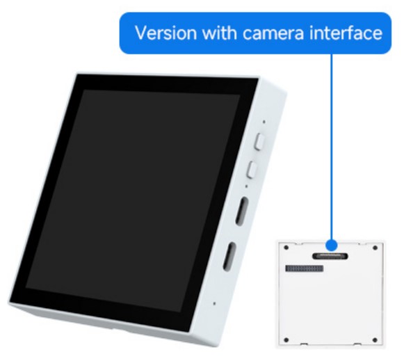
- Onboard MIPI-CSI high-definition camera port, support full HD 1080P picture acquisition and encoding, integrated image signal processor (ISP) and H264 video encoder, support H.264 & JPEG video encoding (1080P @30fps), easy to apply to computer vision, machine vision and other fields
- Onboard MIPI-DSI high-definition screen display port, integrated pixel processing accelerator (PPA), 2D graphics acceleration controller (2D DMA), supporting JPEG image decoding (1080P @30fps), providing strong support for high-definition screen display and smooth HMI experience, convenient for application to smart home central control screen, industrial central control screen, vending machine and other scenarios
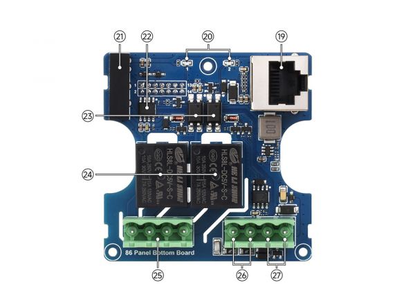
Hardware Description
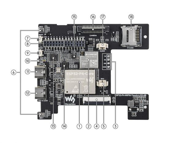
1. ESP32-P4-Core 2. ESP32-C6-MINI-1U-H8 module 3、2.54 4PIN solder pad 4. MIPI DSI LCD port 5. RTC battery header 6. SMD microphone 7. BOOT button 8. Expansion header (2.0mm pitch) | 9. RESET button 10. PWR LED indicator 11. Type-C port USB OTG 12. Type-C port USB TO UART 13. ES7210 echo cancellation algorithm chip 14. IP101 15. ES8311 Low-power audio codec chip 16. MIPI CSI port |
18. TF card slot 19. 100MB RJ45 network port 20. Relay working indicator 21. Power isolation module 22. Digital isolator 23. Optocoupler isolation 24. Relay 25. Relay terminal block 26. RS485 terminal block 27. Power port |
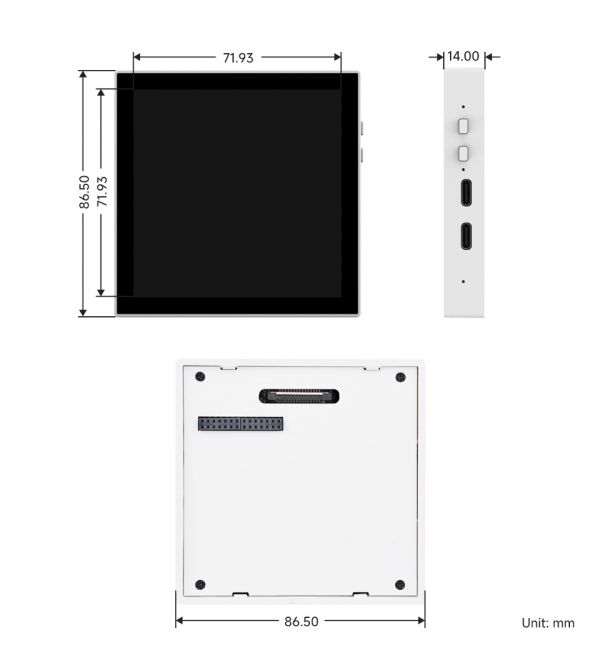
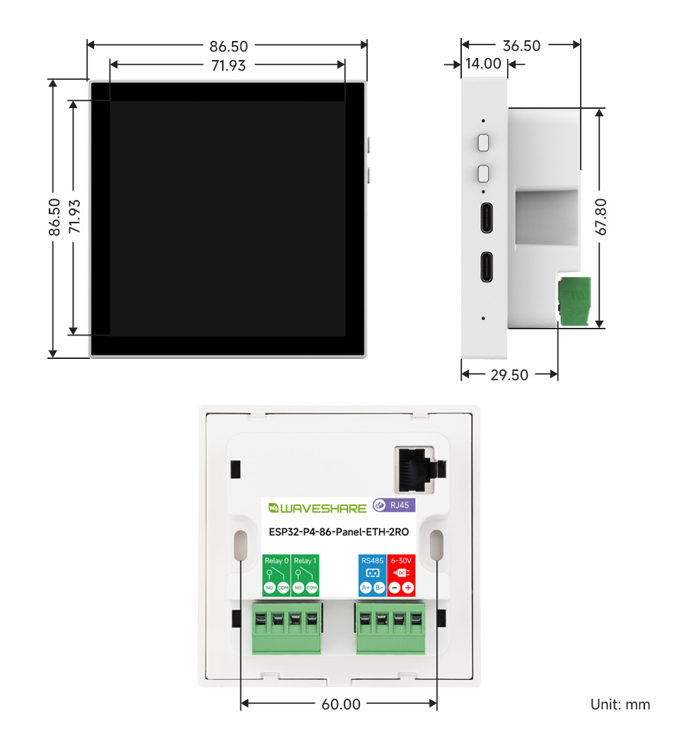
Dimensions
ESP32-P4-WIFI6-Touch-LCD-4B
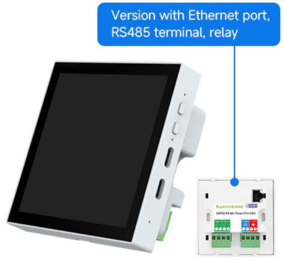
ESP32-P4-86-Panel-ETH-2RO
Version Description
Usage Instructions
This tutorial is designed to guide users to set up a software environment for ESP32-P4 hardware development, and show how to use the ESP-IDF configuration menu and compile and download the firmware to the ESP32-P4 development board through simple examples.
- Preparation
- Hardware
- ESP32-P4-86-Panel-ETH-2RO development board
- USB cable (Type-A to Type-C, prepared as needed)
- Computer (Windows, Linux or macOS)
- Software (it is recommended to use the integrated development environment to install ESP-IDF, if you are familiar with ESP-IDF, you can directly start from the ESP-IDF terminal, you can choose one of the following development methods)
- VSCode + ESP-IDF plug-in (Recommended)
- Eclipse + ESP-IDF plug-in (Espressif-IDE)
- Arduino IDE
- Hardware
Arduino
This chapter introduces setting up the Arduino environment, including the Arduino IDE, management of ESP32 boards, installation of related libraries, program compilation and downloading, as well as testing demos. It aims to help users master the development board and facilitate secondary development.

Environment Setup
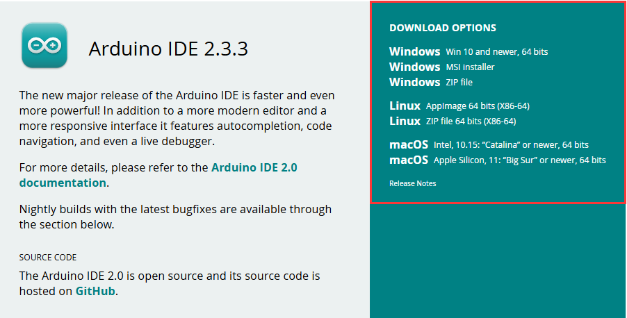
Download and Install Arduino IDE
- Click to visit the Arduino official website, select the corresponding system and system bit to download
- Run the installer and install all by default
Install ESP32 Development Board
- Before using ESP32-related motherboards with the Arduino IDE, you must first install the software package for the esp32 by Espressif Systems development board
- According to board installation requirement, it is generally recommended to use Install Online. If online installation fails, use Install Offline.
- For the installation tutorial, please refer to Arduino board manager tutorial
| Board name | Board installation requirement | Version number requirement |
|---|---|---|
| esp32 by Espressif Systems | "Install Offline" / "Install Online" | ≥3.2.0 |
Install Library
- When installing Arduino libraries, there are usually two ways to choose from: Install online and Install offline. If the library installation requires offline installation, you must use the provided library file
For most libraries, users can easily search and install them through the online library manager of the Arduino software. However, some open-source libraries or custom libraries are not synchronized to the Arduino Library Manager, so they cannot be acquired through online searches. In this case, users can only manually install these libraries offline. - ESP32-P4 library file is stored in the demo
- For library installation tutorial, please refer to Arduino library manager tutorial
| Library Name | Description | Version | Library Installation Requirement |
|---|---|---|---|
| GFX_Library_for_Arduino | GFX graphical library for SH8601 | v1.6.0 | "Install Offline" |
| lvgl | LVGL graphical library | v9.3.0 | "Install Offline" is recommended |
| displays | I2C driver, screen definition and touch driver | —— | "Install Offline" |
| lv_conf.h | LVGL configuration file | —— | "Install Offline" |
Run the First Arduino Demo
New Project
- Run the Arduino IDE and select
File->New Sketch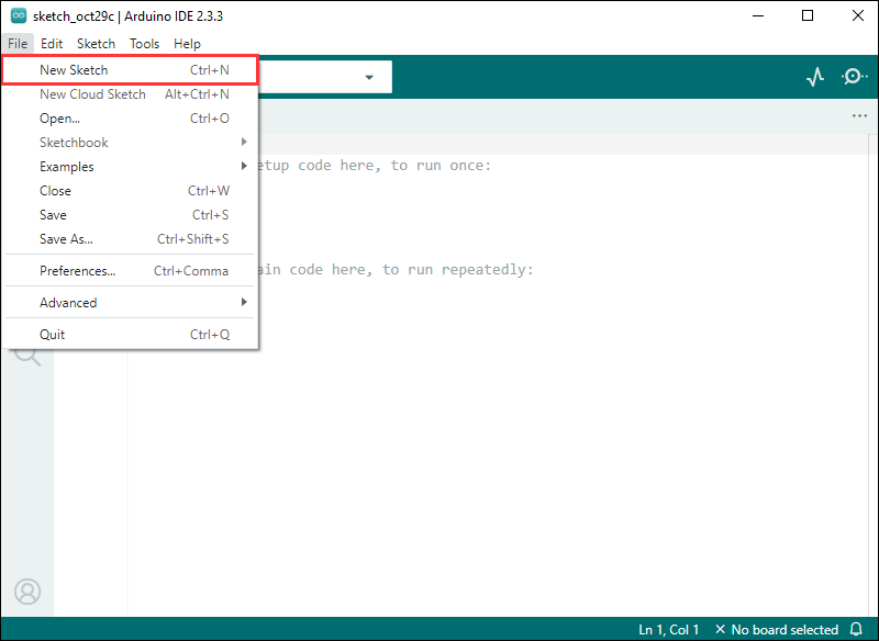
- Enter the code:
void setup() {
  // put your setup code here, to run once:
  Serial.begin(115200);
}

void loop() {
  // put your main code here, to run repeatedly:
  Serial.println("Hello, World!");
  delay(2000);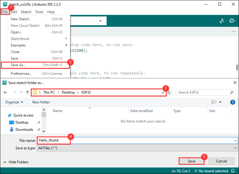
}- Save the project and select
File->Save As.... In the pop-up menu, select the path to save the project, and enter a project name, such as Hello_World, clickSave
Compile and Flash Demos
- Select the corresponding development board, take the ESP32S3 motherboard as an example:
①. Click to select the dropdown menu option Select Other Board and Port;
②. Search for the required development board model esp32s3 dev module and select;
③. Select COM Port;
④. Save the selection.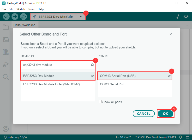
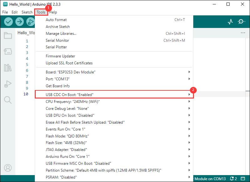
- If the ESP32S3 mainboard only has a USB port, you need to enable USB CDC, as shown in the following diagram:
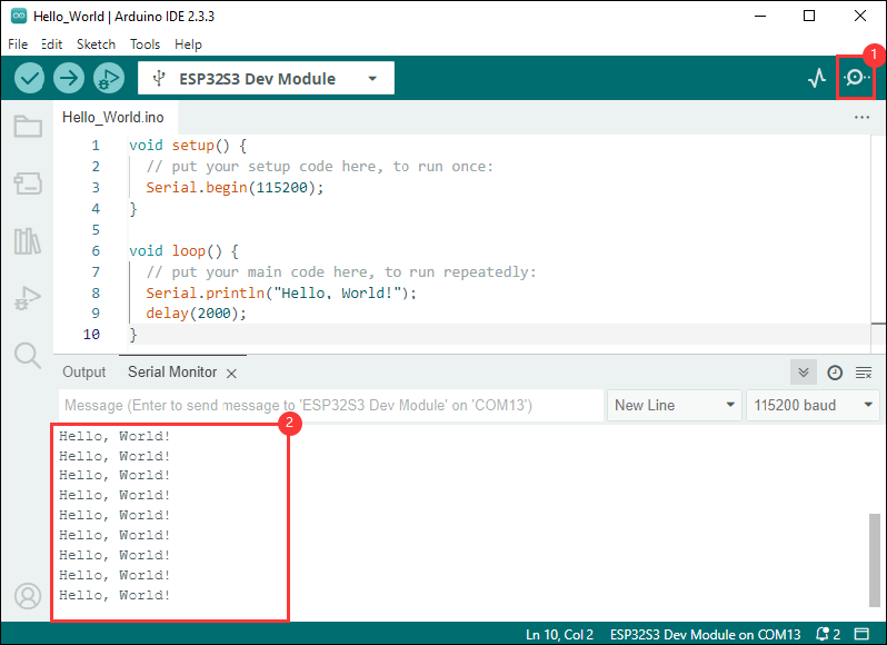
- Compile and upload the program:
①. Compile the program; ②. Compile and download the program; ③. Download successful.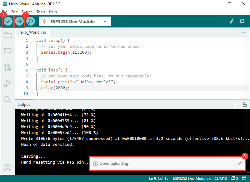
- Open the Serial Monitor window, and the demo will print "Hello World!" every 2 seconds, and the operation is as follows:
Demo

| Demo | Basic Description | Dependency Library |
|---|---|---|
| HelloWorld | Demonstrates the basic graphics library function and can also be used to test the basic performance of display screens and the display effect of random text | GFX_Library_for_Arduino, displays |
| Drawing_board | Touch drawing dot test | GFX_Library_for_Arduino, displays |
| AsciiTable | Prints ASCII characters in rows and columns on the display screen according to the screen size | GFX_Library_for_Arduino, displays |
| GFX_ESPWiFiAnalyzer | Draws the WiFi band signal strength on the screen | GFX_Library_for_Arduino, displays |
| LVGLV9_Arduino | LVGL demonstration | LVGL,GFX_Library_for_Arduino, displays |
- ESP32-P4 mode: ESP32P4 DEV Module
ESP-IDF
Introduction to ESP-IDF and Environment Setup (VSCode Column)
ESP-IDF (Espressif IoT Development Framework) is an open-source IoT development framework launched by Espressif specifically for the development of its ESP32 series chips. ESP-IDF provides the necessary tools and libraries to build IoT applications, including Wi-Fi, Bluetooth, peripheral drivers, file systems, network protocol stacks, encryption, security, and real-time operating systems (FreeRTOS).
The following description only applies to the VSCode + ESP-IDF environment
- PS:
- If you wish to use the Eclipse editor as your primary development environment, please click the link to download Espressif-IDE and install it, replacing the ESP-IDF version to be ≥v5.3.1.
- If you encounter errors such as TSL Error, Network Error, etc., during the installation of ESP-IDF, please re-clear the directory folders, ensure a stable network environment without any proxy contamination, and then try the installation again. It will take a long time, so please be patient.
Prerequisites
- If you are using a Mac or Linux, install the following ESP-IDF prerequisites. If you're using Windows, ignore this step.
Install VSCode
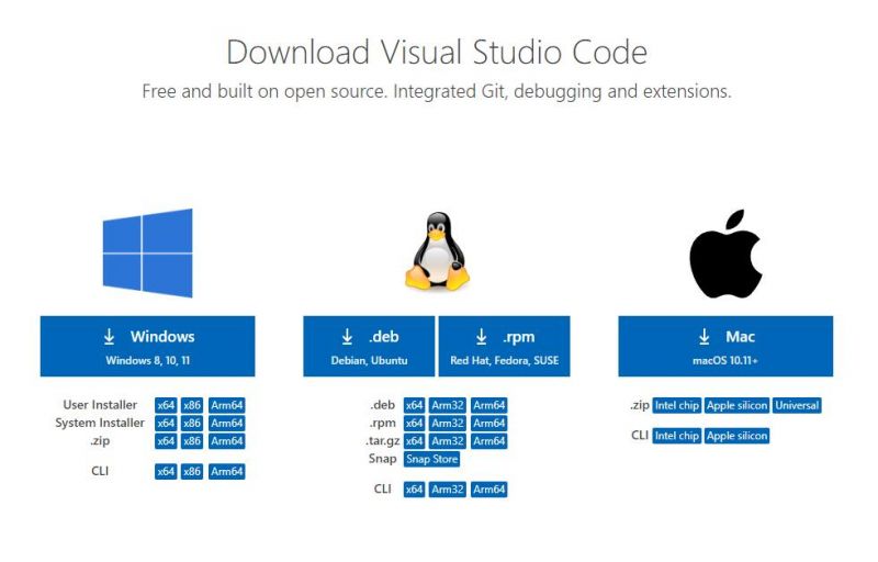
- Open the download page of the official VSCode website, and select the corresponding system and system bit to download
- After running the installation package, the rest can be installed by default, but here for the subsequent experience, it is recommended to check boxes 1, 2, and 3
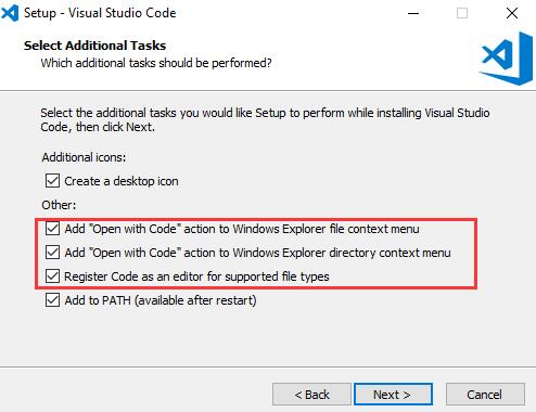
- After the first and second items are enabled, you can open VSCode directly by right-clicking files or directories, which can improve the subsequent user experience
- After the third item is enabled, you can select VSCode directly when you choose how to open it
Install the ESP-IDF Plug-in
- Open VSCode, click on Plugin Manager, and search for ESP-IDF to download and install, as shown in the figure:
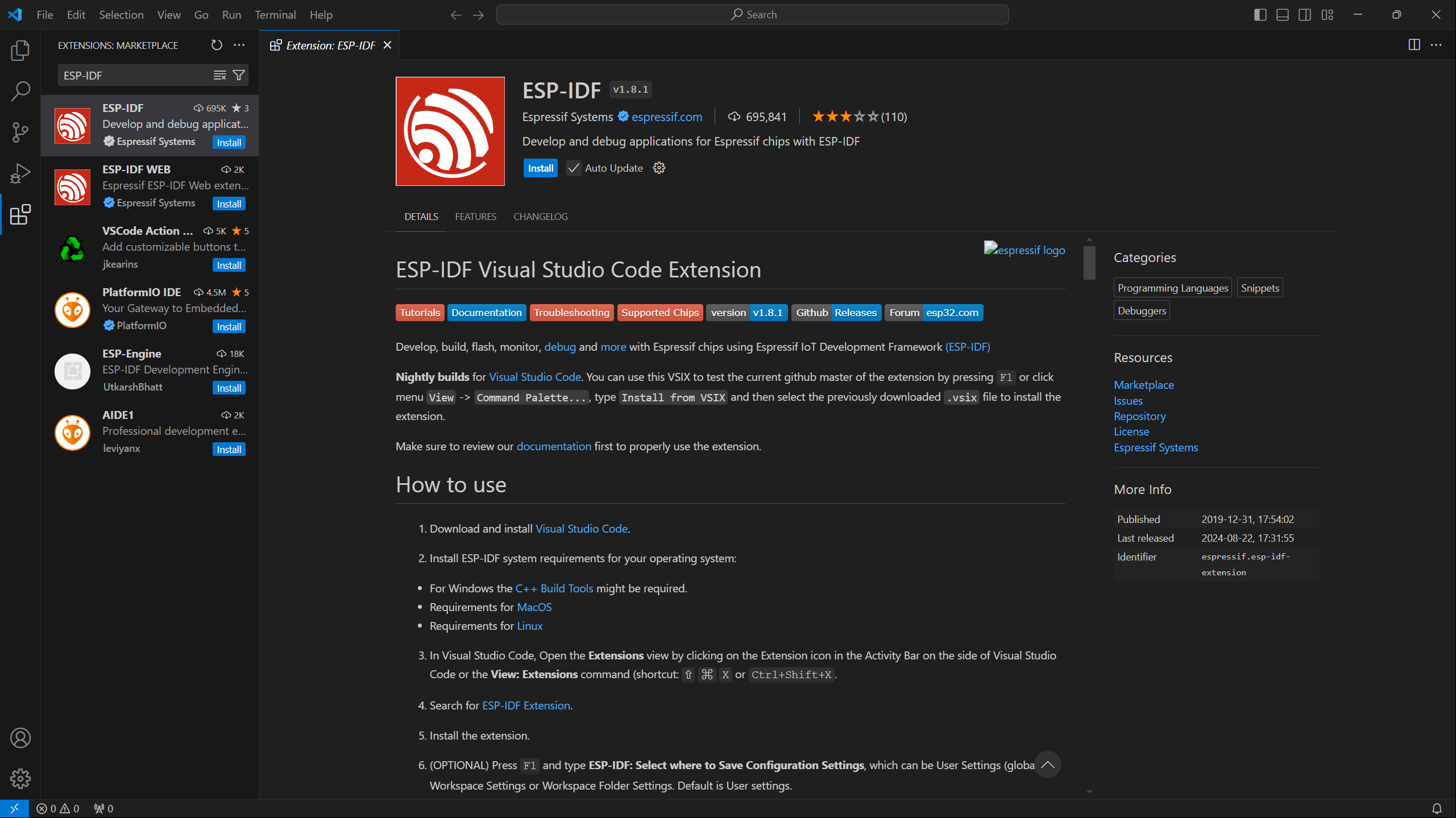
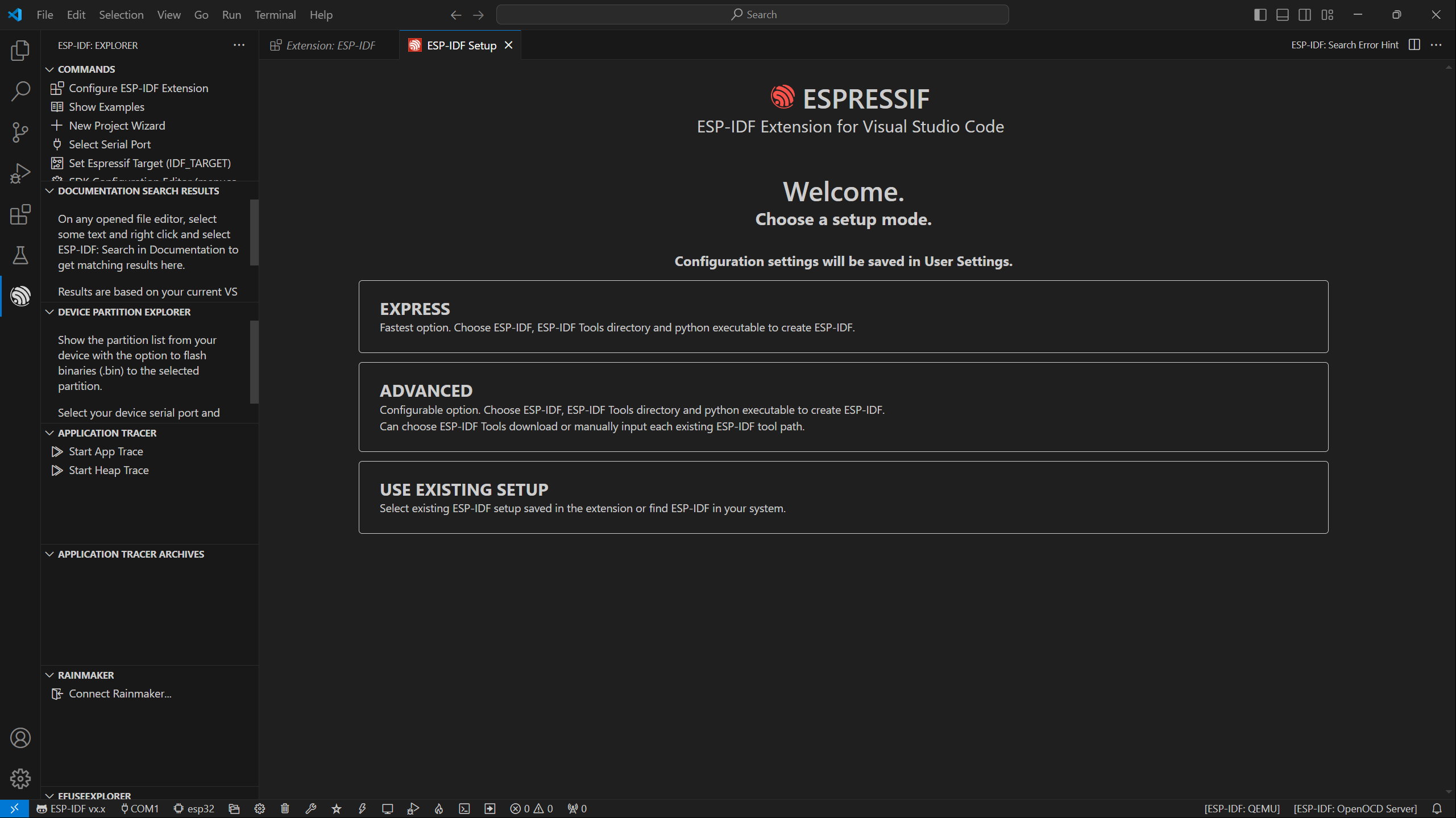
- After installation, there is an Espressif logo on the left toolbar is a plug-in, click into the plug-in (there will be a short period of time for loading the program), select EXPRESS, for quick installation, as shown in the figure:
Install the ESP-IDF Development Environment
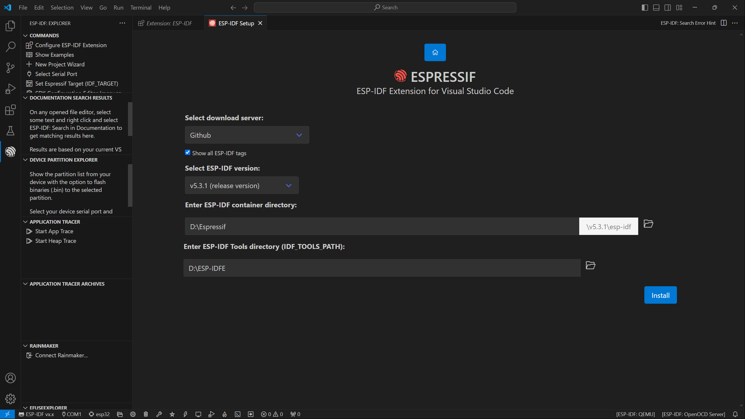
- Enter the EXPRESS installation interface, confirm the ESP-IDF version ≥v5.3.1 release version, ESP-IDF directory and ESP-IDF tool directory, click Install, and wait patiently for the installation steps to be completed, as shown in the figure:
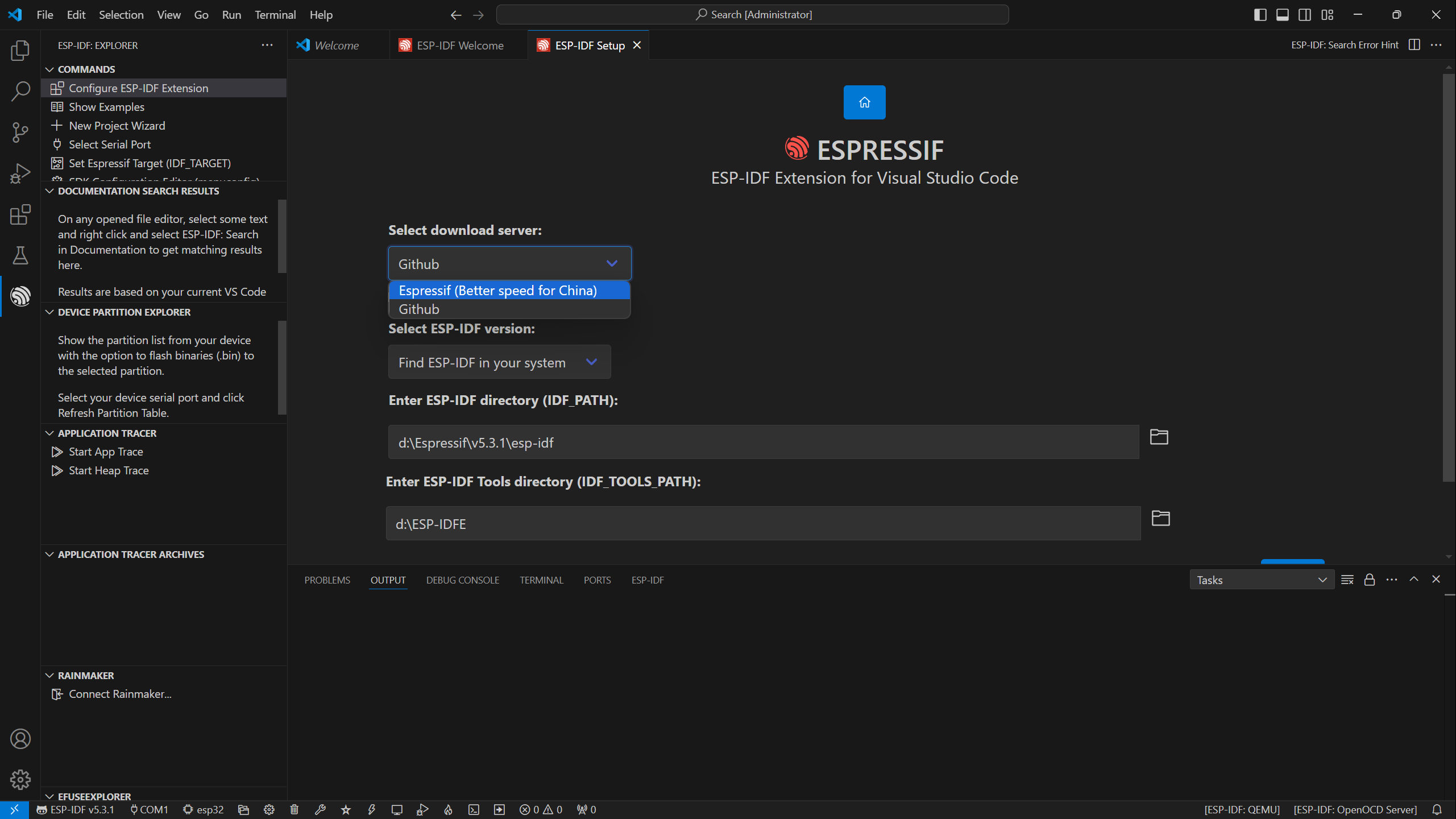
- If you are a domestic user in China, you can choose to download the server as Espressif, the installation process is slow, make sure the network is in good condition, you can wait patiently for the installation to complete,
- The installation process is as follows:
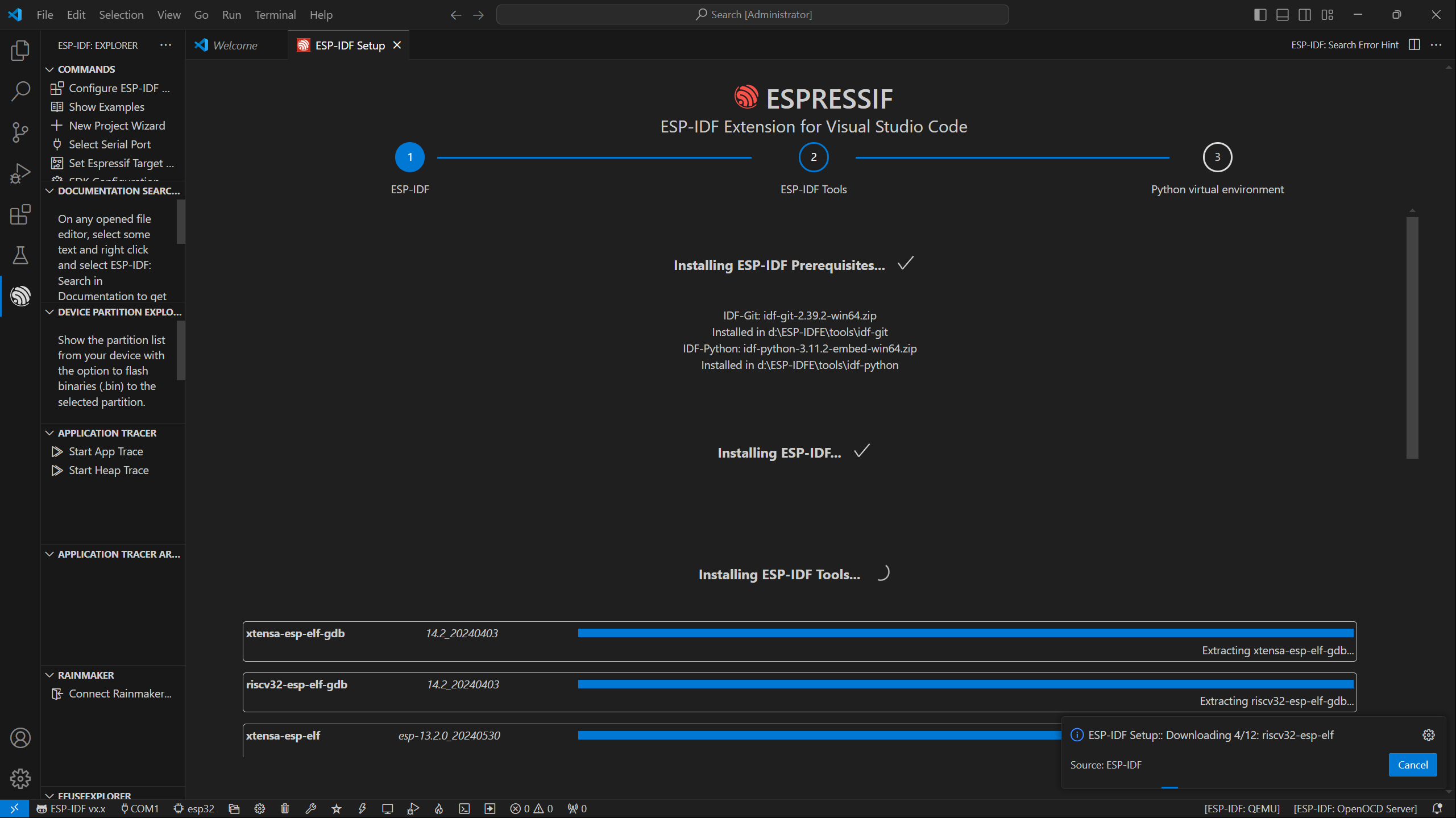
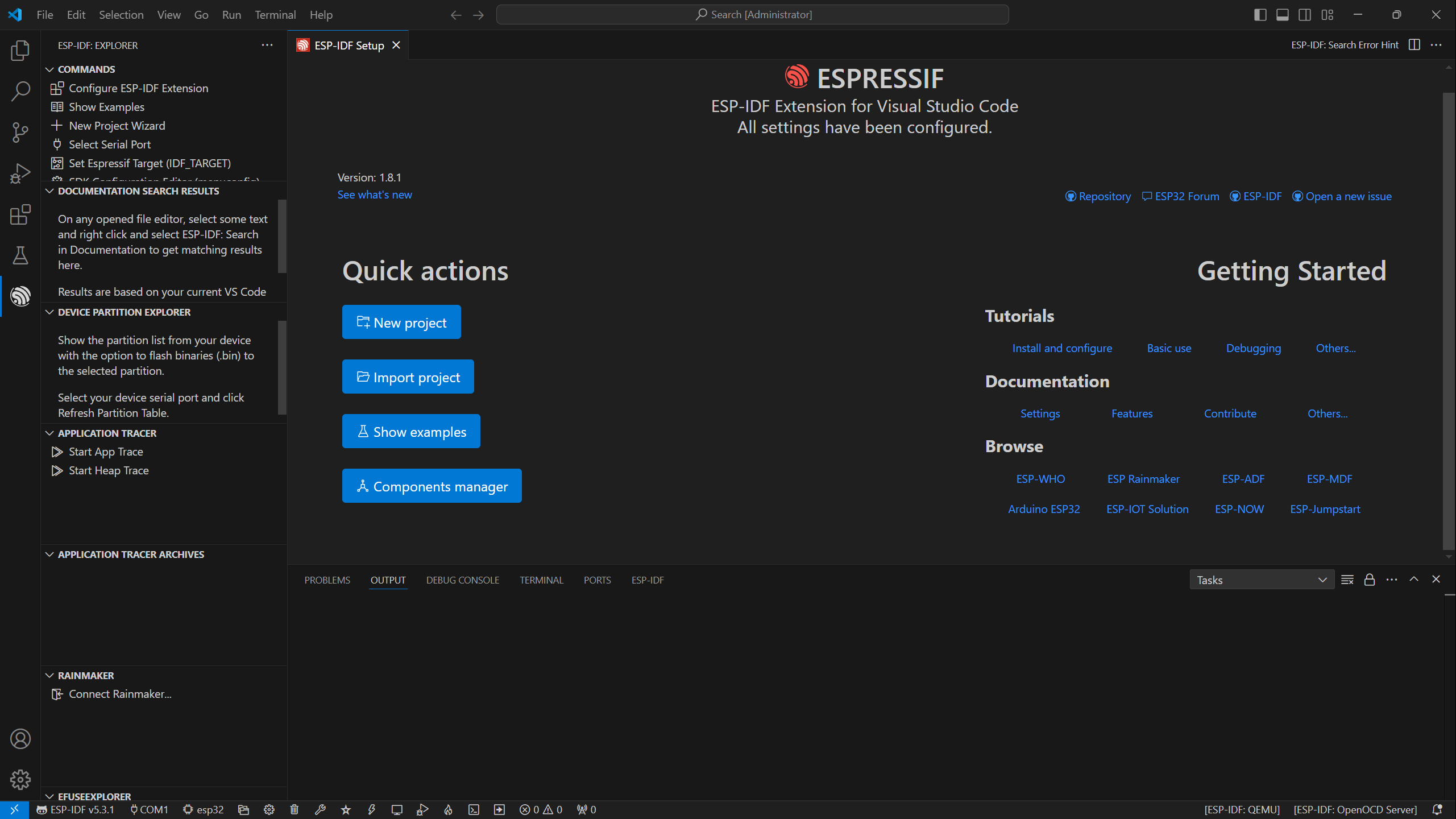
- After the installation is complete, the interface is as follows:
Getting Start
The best way to learn a language or development environment is to start from the basics. This section will provide a detailed guide on how to create projects, develop from existing projects, and include embedded classic tutorials such as HelloWorld and the usage of common port I2C
Introduction to Basic Structure of an ESP-IDF Project
- Open the ESP-IDF plug-in, click New project, select the ESP-IDF demo -- >sample_project -- > click Create
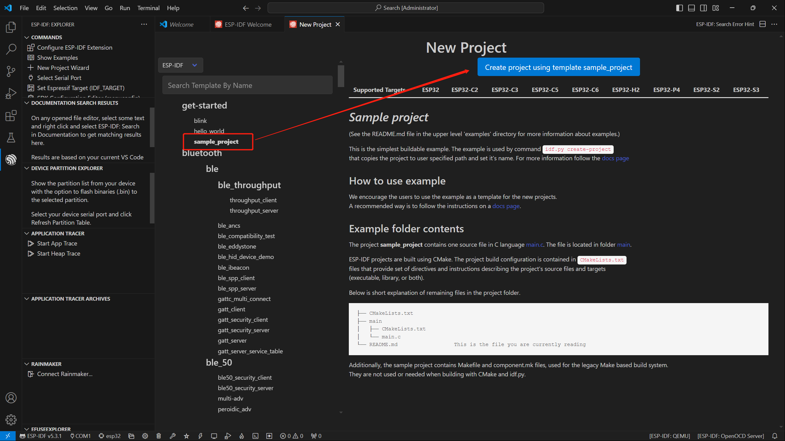
- Create a new VSCode and open it in the window, you can see the structure of VSCode as follows
├── CMakeLists.txt
├── main
│   ├── CMakeLists.txt
│   └── main.c
└── README.md
ESP-IDF Project Details
- Component: The components in ESP-IDF are the basic modules for building applications, each component is usually a relatively independent code base or library, which can implement specific functions or services, and can be reused by applications or other components, similar to the definition of libraries in Python development.
- Component reference: The import of libraries in the Python development environment only requires to "import library name or path", while ESP-IDF is based on the C language, and the importing of libraries is configured and defined through
CMakeLists.txt. - When we use online components, we usually use
idf.py add-dependency <componetsName>to add online components to the project, which generates aidf_component.ymlfile for managing components. - The purpose of CmakeLists.txt: When compiling ESP-IDF, the build tool
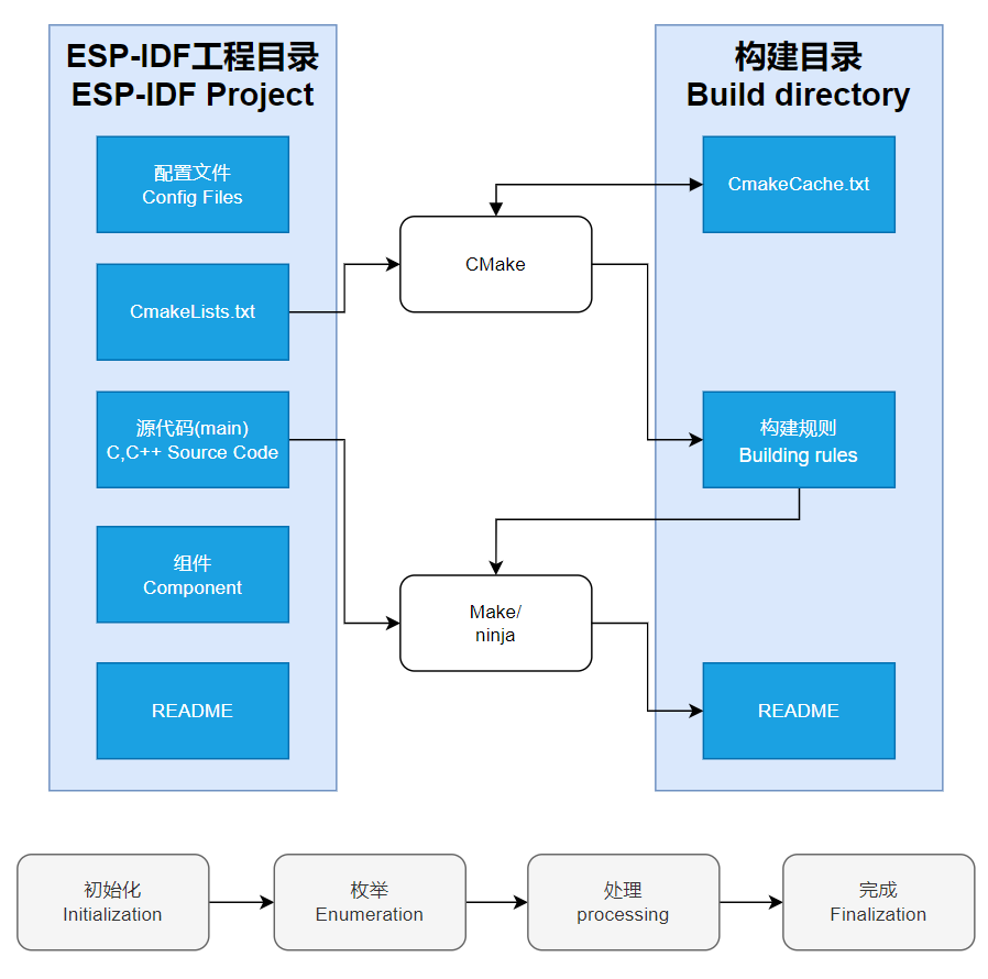
CMakefirst reads the content of the top-levelCMakeLists.txtin the project directory to read the build rules and identify the content to be compiled. When the required components and demos are imported into theCMakeLists.txt, the compilation toolCMakewill import each content that needs to be compiled according to the index. The compilation process is as follows:
- Component reference: The import of libraries in the Python development environment only requires to "import library name or path", while ESP-IDF is based on the C language, and the importing of libraries is configured and defined through
Description of Bottom Toolbar of VSCode User Interface
When we open an ESP-IDF project, the environment is automatically loaded at the bottom. For the development of ESP32-P4-86-Panel-ETH-2RO, the bottom toolbar is also very important, as shown in the figure: 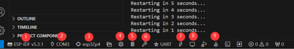
- ESP-IDF Development Environment Version Manager, when our project requires differentiation of development environment versions, it can be managed by installing different versions of ESP-IDF. When the project uses a specific version, it can be switched to by utilizing it
- Device flashing COM port, select to flash the compiled program into the chip
- Select set-target chip model, select the corresponding chip model, for example, ESP32-P4-86-Panel-ETH-2RO needs to choose
esp32p4as the target chip - menuconfig, click it to Modify sdkconfig configuration file
- Fullclean button, when the project compilation error or other operations pollute the compiled content, you can clean up all the compiled content by clicking it
- Build project, when a project satisfies the build, click this button to compile
- Flash button, when a project build is completed, select the COM port of the corresponding development board, and click this button to flash the compiled firmware to the chip
- Monitor enable flashing port monitoring, when a project passes through Build --> Flash, click this button to view the log of output from flashing port and debugging port, so as to observe whether the application works normally
- Build Flash Monitor one-click button, which is used to continuously execute Build->Flash->Monitor, often referred to as "little flame"
HelloWorld Demo
After understanding Description of bottom toolbar of VSCode user interface, the HelloWorld project allows you to quickly get started and understand the basic projects of the ESP32 development environment. It demonstrates how to use ESP-IDF to create a basic application, and covers the ESP32 development process, including compilation, flashing, and monitor debugging steps.
- After opening the sample project
HelloWorld, set the target port and chip type (Note: There is a loading action in the lower right corner when the chip type is selected, indicating that ESP-IDF is executing the commandidf.py set-target esp32p4. It needs to pull the architecture package environment corresponding to the chip from the package manager, which may take some time. Please wait patiently. If you perform build or other operations at this time, there will be errors!!! ) - Through the bottom tool with one click, you can build, flash, and monitor, allowing you to view the terminal output of "Hello World"!
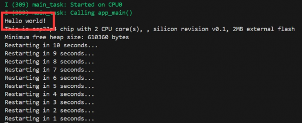
- Code content analysis
- There is only one
app_mainmain function in the code, which determines the print content output through conditional judgment, and adds a loop at the end to achieve 10s restart of the chip. app_mainfunction is the entry point for user applications in the ESP-IDF (Espressif IoT Development Framework) development framework. It is the core function of the ESP-IDF project and is equivalent to the main function in the standard program of the C language. In ESP32 development,app_mainfunction is the first task scheduled by the real-time operating system (FreeRTOS), which is the starting point for the execution of the user's code.
- There is only one
I2C
I2C is a commonly used serial communication bus, which can communicate through two lines, one data cable (SDA, Serial Data) and one clock cable (SCL, Serial Clock), and supports multi-master and multi-slave mode. On the ESP32-P4, there are two I2C bus ports. The chip internally uses a GPIO exchange matrix to configure the use of any GPIO pins. This feature allows us to freely use any GPIO as an I2C pin control. Of course, the ESP32-P4 I2C supports both Slave and Master modes. Below, we primarily use the I2C host (Master) mode for ESP32-P4 to start communication, control, send data requests or receive data from the slave devices (which can be sensors from any I2C port). The I2C pins of ESP32-P4-86-Panel-ETH-2RO use SCL(GPIO8) and SDA(GPIO7) by default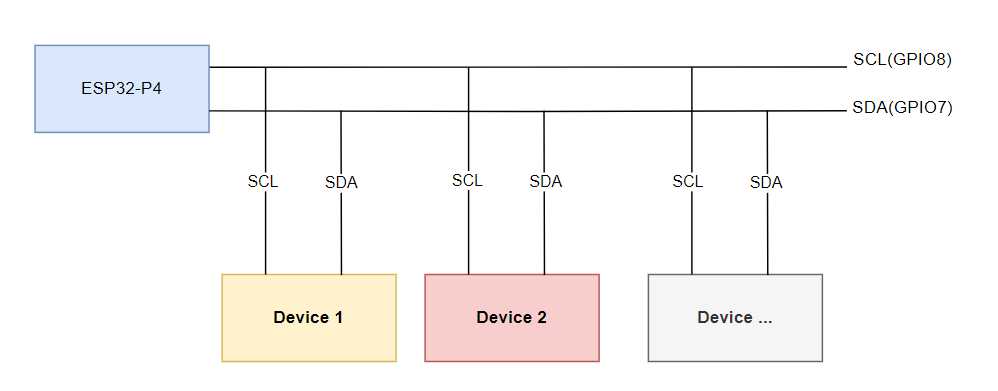
In ESP-IDF, the I2C bus requires the configuration specified by i2c_master_bus_config_t:
i2c_master_bus_config_t::clk_sourceselects the source clock for the I2C bus, using the default I2C clock source (usually the default clock source) is simply set toI2C_CLK_SRC_DEFAULTi2c_master_bus_config_t::i2c_portsets the I2C port used by the controller, as explained above, the ESP32-P4 has two I2C ports. When two different I2C ports need to be enabled simultaneously, this needs to be utilized to distinguish between themi2c_master_bus_config_t::scl_io_numsets the GPIO number of the serial clock bus (SCL), which is 8 on ESP32-P4-86-Panel-ETH-2ROi2c_master_bus_config_t::sda_io_numsets the GPIO number for the serial data bus (SDA), which is 7 on the ESP32-P4-86-Panel-ETH-2ROi2c_master_bus_config_t::glitch_ignore_cntsets the Glitch Period for the Master Bus, and if the Glitch Period on the line is smaller than this value, it can be filtered out. Typically, this value is set to 7i2c_master_bus_config_t::enable_internal_pullupenables internal pullups, on the ESP32-P4-86-Panel-ETH-2RO, there is already an additional I2C pullup, no need to enable internal pullups
As described above, the I2C configuration is:
   i2c_master_bus_config_t i2c_bus_config = {
       .clk_source = I2C_CLK_SRC_DEFAULT,
       .i2c_port = I2C_NUM_0,
       .scl_io_num = 8,
       .sda_io_num = 7,
       .glitch_ignore_cnt = 7,
       .flags.enable_internal_pullup = false,
   };
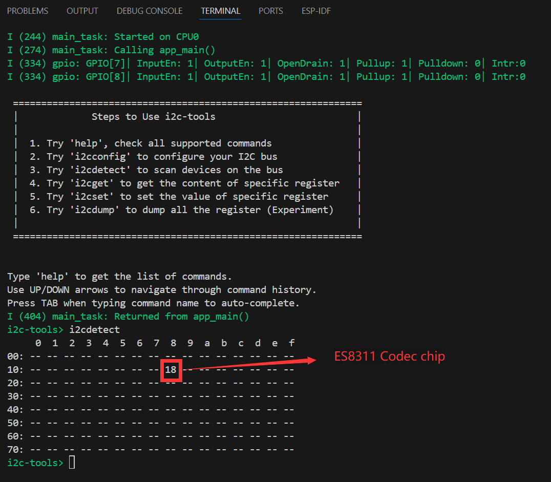
- Open the
i2c_toolsthe project, select the COM port and chip model, click to enter the settings. This will open a new tab: SDK Configuration editor, also known as menuconfig. Directly search for I2C in the search bar. The content has already been retrieved, and the SCL GPIO Num and SDA GPIO Num in the demo are already corresponding toSCL(GPIO8)andSDA(GPIO7) - Next, you can directly compile, flash, and monitor by clicking . Upon after completion, you will see the command menu in the terminal. When you execute i2cdetect, all I2C addresses will be printed. If there is a device, a number will be displayed (I2C address 18 device corresponds to the onboard ES8311 Codec audio chip, this chip will be detailed in the I2S section), as shown in the figure:
- The above steps have realized the basics of I2C device communication. In devices that use the I2C communication protocol, it is often necessary to write register configurations to the corresponding address device via the I2C bus to achieve the functionality of the I2C device. In this case, we need to write the initialization program for the I2C device in the program to drive the I2C device. Different I2C devices have different I2C addresses. In development, we can use the i2ctools tool to query the attached I2C address, nd then read the chip manual to query the registers, configuration and other contents to achieve I2C bus communication.
Intermediate
SDMMC Demo
The ESP32-P4-86-Panel-ETH-2RO features a 4-Wire SDIO3.0 card slot for off-chip memory expansion
- Supported rate modes
- Default rate (20 MHz)
- High-speed mode (40 MHz)
- Configure bus width and frequency
In ESP-IDF, use sdmmc_host_t and sdmmc_slot_config_t settings to configure the default 20MHz communication frequency and 4-wire width communication, as follows:
sdmmc_host_t host = SDMMC_HOST_DEFAULT();
sdmmc_slot_config_t slot_config = SDMMC_SLOT_CONFIG_DEFAULT();
In the design that supports 40 MHz communication, you can adjust the max_freq_khz field in the sdmmc_host_t structure to increase the bus frequency:
sdmmc_host_t host = SDMMC_HOST_DEFAULT();
host.max_freq_khz = SDMMC_FREQ_HIGHSPEED;
The SDMMC 4-wire connection on the ESP32-P4-86-Panel-ETH-2RO should be defined as:
sdmmc_slot_config_t slot_config = SDMMC_SLOT_CONFIG_DEFAULT();
slot_config.width = 4;
slot_config.clk = 43;
slot_config.cmd = 44;
slot_config.d0 = 39;
slot_config.d1 = 40;
slot_config.d2 = 41;
slot_config.d3 = 42;
slot_config.flags |= SDMMC_SLOT_FLAG_INTERNAL_PULLUP;
- Open the
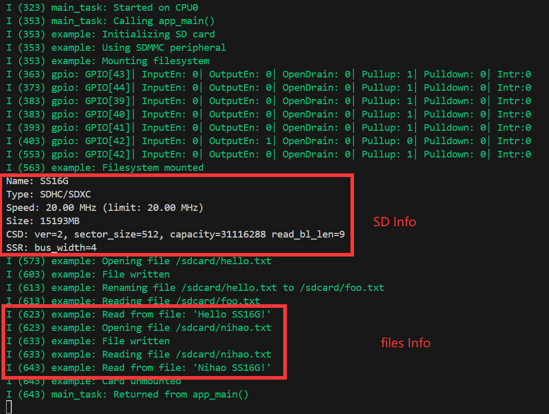
sdmmcproject, select the COM port and chip model, because the demo project defines the pin as a macro, so you need to configure it, of course, you can also directly fill in the pin value. Click to enter the settings, here a new tab will open: SDK Configuration editor, which is also known as menuconfig. We directly search for sd in the search bar, see that the content has been retrieved at this time, and the demo configuration has been configured, check the default initialization and create the demo file by default: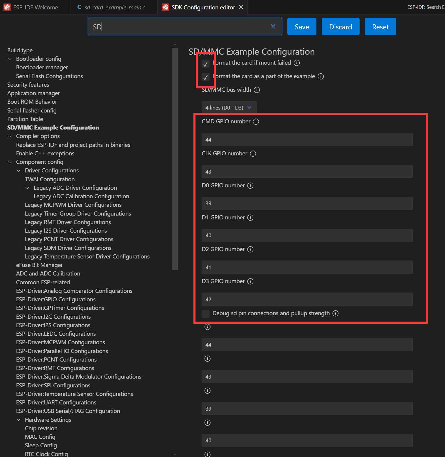
- Next, insert the prepared TF card, click to compile, flash and monitor. After completion, you will see the output of the command menu in the terminal showing the contents of the files in the directory:
WIFI Networking Demo
The ESP32-P4 does not come with WIFI/BT capabilities by itself, whereas the ESP32-P4-86-Panel-ETH-2RO extends its WIFI functionality by connecting to an ESP32-C6 module via SDIO. The ESP32-C6 acts as a Slave, supporting the ESP32-P4 as the Host utilizing the WIFI 6/BT 5 features through SDIO via a series of instruction sets. By adding two components, seamless use of esp_wifi is achieved.
// In a WIFI project, add the following two components through the ESP-IDF component management tool
idf.py add-dependency "espressif/esp_wifi_remote"
idf.py add-dependency "espressif/esp_hosted"
- Open the
wifistationproject to add components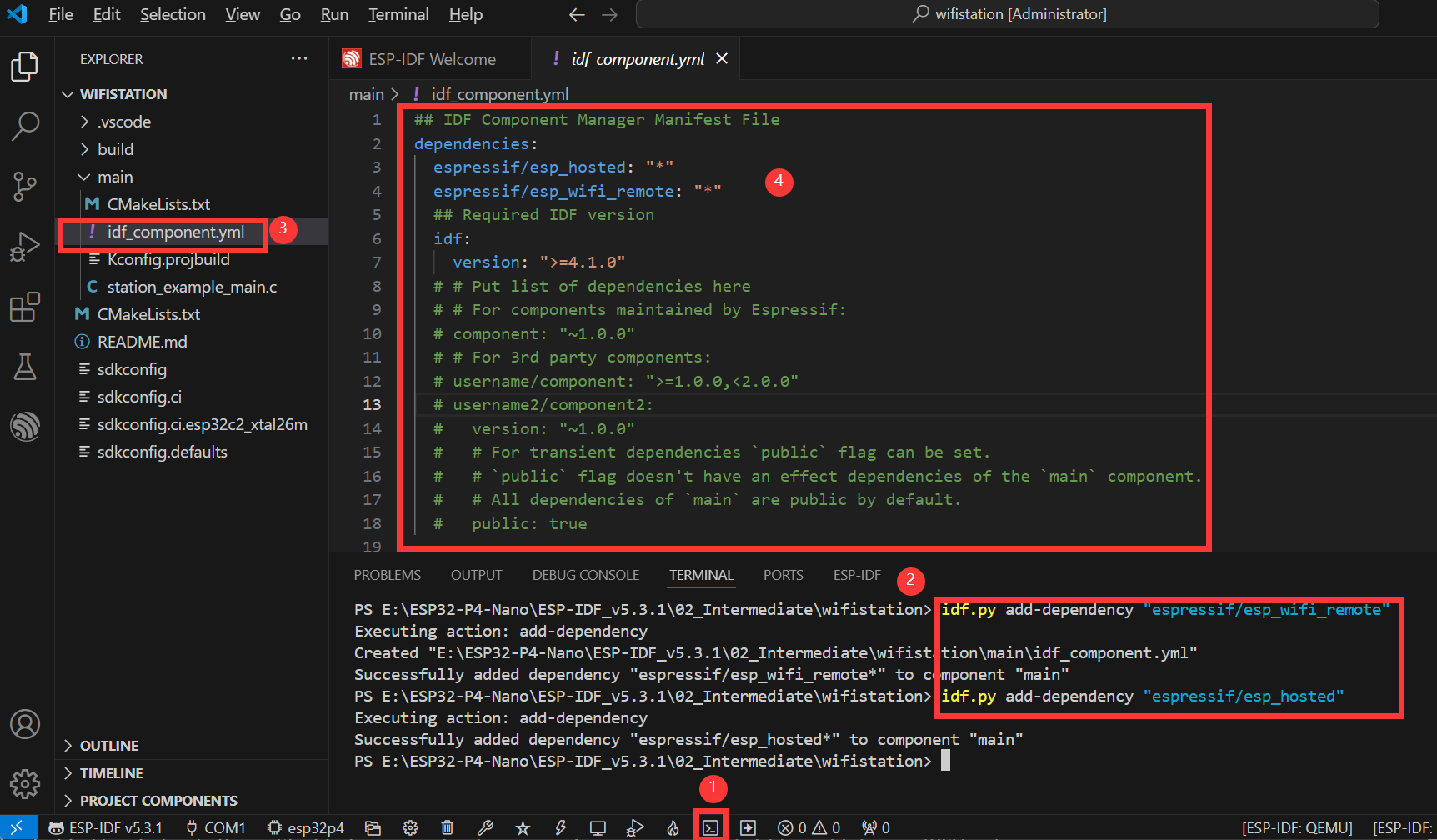
- As shown in the above figure, these are the specific steps to add components
- Open the ESP-IDF terminal
- Add the required components in Terminal
- After successful addition, there will be an additional
idf_component.ymlin the main folder of the project, which is used to manage project components, as explained in the ESP-IDF Project Catalog section - After opening, it can be seen that two poments
espressif/esp_hosted: "*"andespressif/esp_wifi_remote: "*"have been added. They are added to the project as you build it
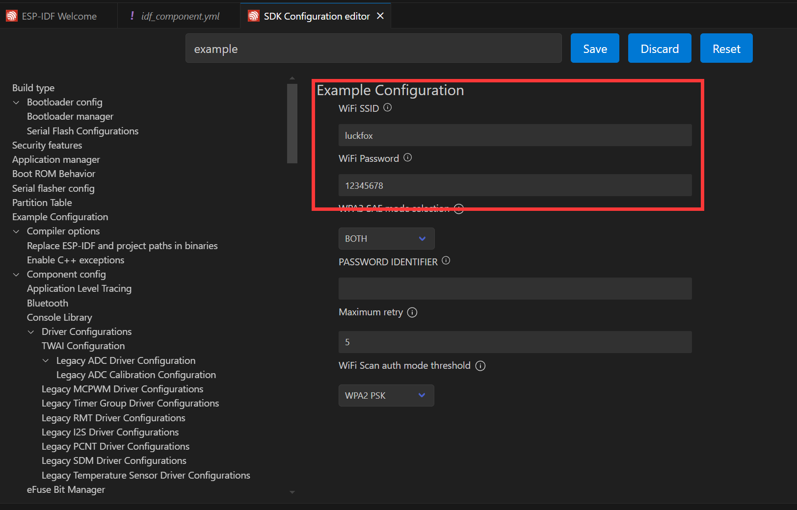
- Next, you can open the settings by clicking on . Input "Example" for the search, here you set the ssid and password for the WiFi you want to connect to. Note that ESP32-C6 supports 2.4GHz WiFi-6, so when choosing your target WiFi, make sure the frequency is 2.4GHz. After making the changes, you need to save them, otherwise, there will be an error!
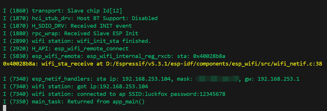
- Next, you can directly compile, flash, and monitor by clicking . After completion, you will see the following results on the terminal, at this point the ESP32-P4-86-Panel-ETH-2RO has already connected to WIFI and is online:
I2S Audio Demo
I2S (Inter-IC Sound) is a digital communication protocol for transmitting audio data. I2S is a serial bus interface that is primarily used for digital audio data transmission between audio devices, such as digital audio processors (DSPs), digital-to-analog converters (DACs), analog-to-digital converters (ADCs), and audio codecs.
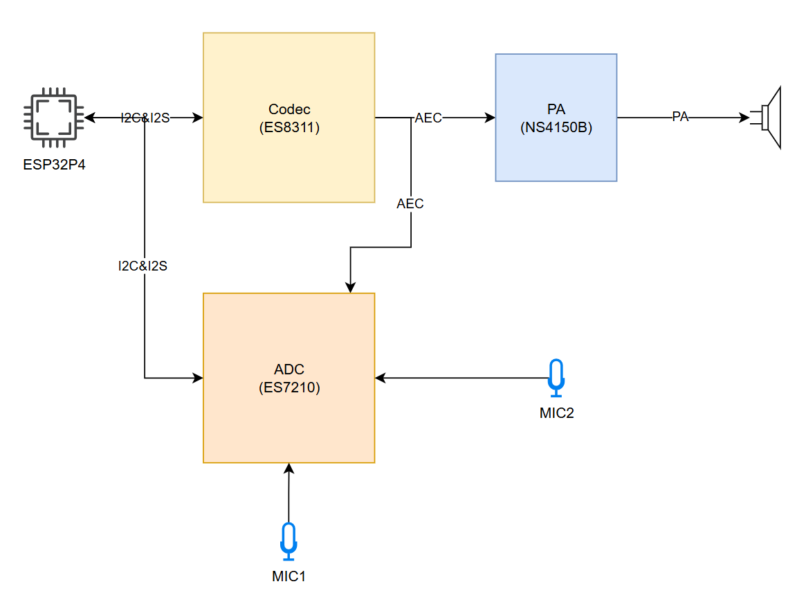
The ESP32-P4 includes 1 I2S peripheral. By configuring these peripherals, the sample data can be input and output with the help of an I2S driver. ESP32-P4-86-Panel-ETH-2RO board integrates the es8311 codec chip and the NS4150B power amplifier chip combination. The I2S bus and pin distribution are as follows:
- MCLK (Master Clock): Master clock signal. The clock is typically provided to the ES8311 by an external device (such as an MCU or DSP), which serves as the clock source for its internal digital audio processing module.
- SCLK (Serial Clock): Serial clock signal. This signal is typically used for clock synchronization for I2S data transmission and is generated by the master device to indicate the rate at which the data is transferred. The transmission of each bit of each audio sample requires a clock cycle.
- ASDOUT (Audio Serial Data Output) or DOUT: Audio data output pin. The ES8311 outputs decoded digital audio data to this pin, which is then transmitted to an amplifier chip or other audio device.
- LRCK (Left/Right Clock) or WS (Word Select): Left and right channel selection signals to indicate whether the current data sample belongs to the left or right channel. Typically in the I2S protocol, one clock cycle represents the left channel data and the other clock cycle represents the right channel data.
- DSDIN (Digital Serial Data Input) or DIN: Digital audio data input pin. This pin receives audio data from an external audio device or a master. The ES7210 decodes this data and processes the audio signals through a digital signal processing module, enabled by an echo cancellation algorithm.
| Function Pin | ESP32-P4-86-Panel-ETH-2RO Pin |
|---|---|
| MCLK | GPIO13 |
| SCLK | GPIO12 |
| ASDOUT | GPIO11 |
| LRCK | GPIO10 |
| DSDIN | GPIO9 |
| PA_Ctrl (Power amplifier chip enable pin, active high) | GPIO53 |
The ESP32-P4-86-Panel-ETH-2RO es8311 driver uses ES8311 component (which is about to be deprecated, it is recommended to use esp_codec_dev). It can be added during usage through the IDF Component Manager.
idf.py add-dependency "espressif/es8311"
- Open the
i2scodecproject to add components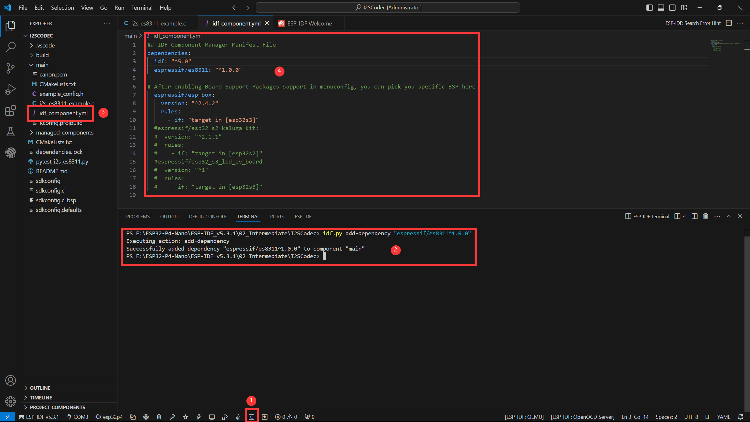
- As shown in the above figure, these are the specific steps to add components
- Open the ESP-IDF terminal
- Add the required components in Terminal
- After successful addition, there will be an additional
idf_component.ymlin the main folder of the project, which is used to manage project components, as explained in the ESP-IDF Project Catalog section - Once opened, you can see that
the espressif/es8311component has been added, and it will be added to the project when you build it
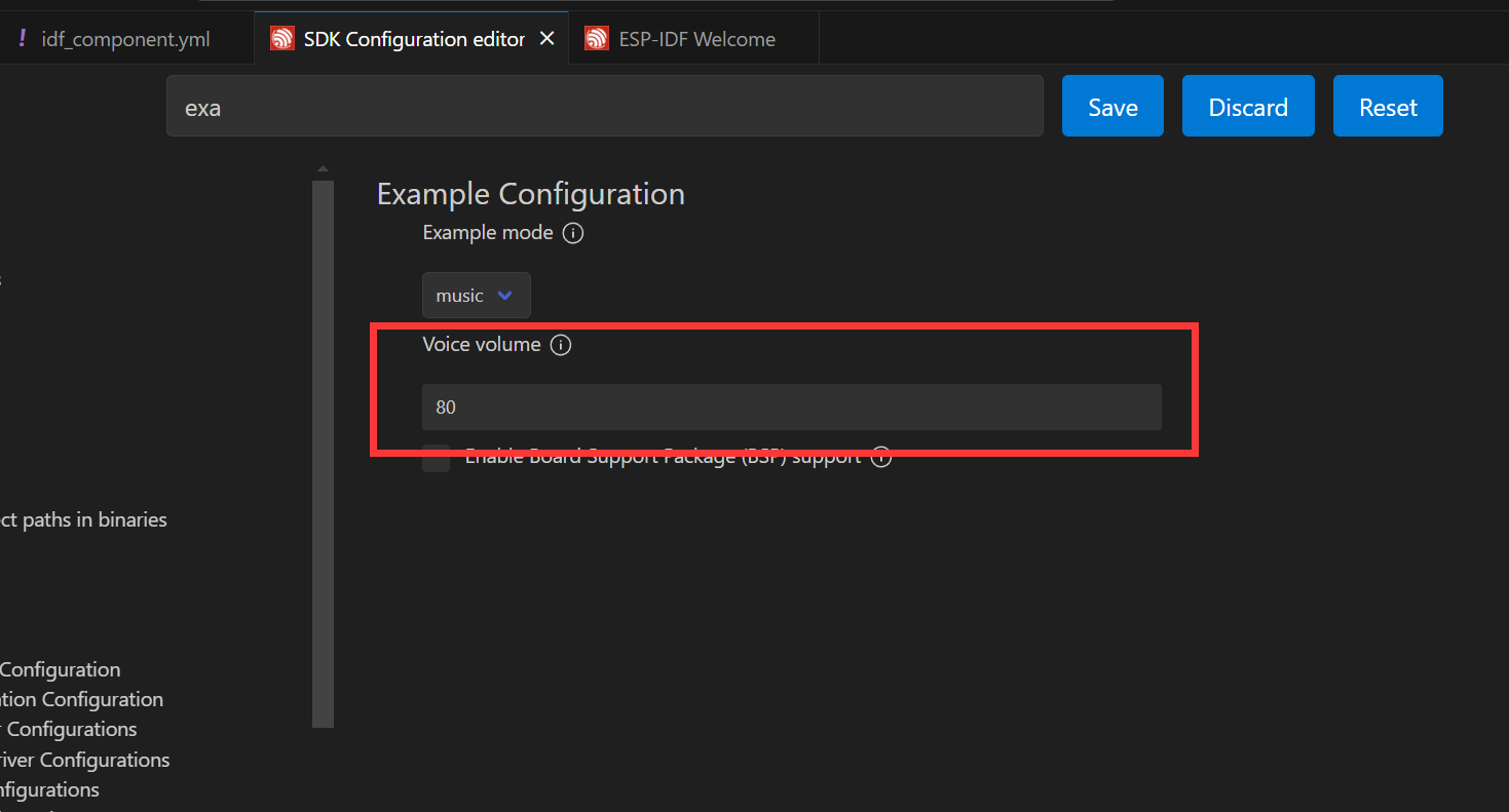
- Next, you can open the settings by clicking on , search for Example, and adjust the appropriate volume
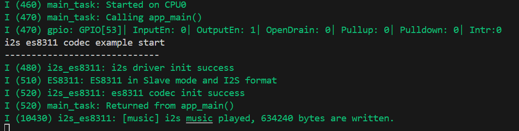
- When connected to the speaker, you can directly compile, flash, and monitor by clicking on it, and the following result will be viewed in the terminal after completion, at this time, ESP32-P4-86-Panel-ETH-2RO is already playing audio
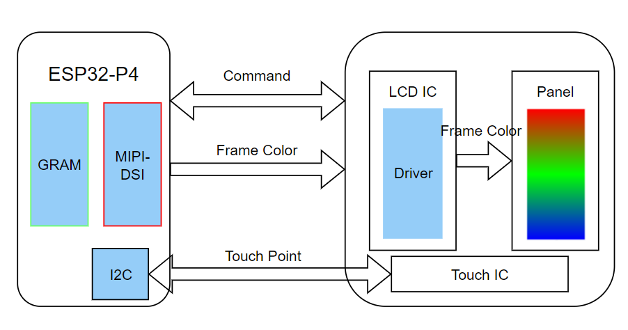
MIPI-DSI Screen Wake-Up Demo
ESP32-P4-86-Panel-ETH-2RO uses the ESP32-P4NRW32 chip with the following new features:
- MIPI-DSI compliant, using D-PHY v1.1 version, up to 2-lane x 1.5Gbps (total 3Gbps)
- Supports RGB888, RGB565, YUV422 input
- Supports RGB888, RGB666, RGB565 output
- Uses video mode to output video streams, and supports output of fixed image patterns
MIPI-DSI image processing can also be processed using a 2D-DMA controller, which supports PPA and JPEG encoding/decoding peripherals
MIPI-DSI LCD Driving Principle
Hardware Required
- ESP32-P4-86-Panel-ETH-2RO
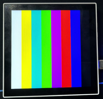
Screen Wake-Up Steps
- After opening the project, select
esp32p4core, and you can directly click to compile, flash, monitor. Upon completion, you can see that the screen has lit up to refresh the color bar:
Advanced
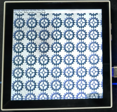
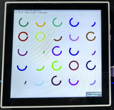
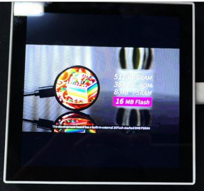
LVGL HMI Human Machine Interaction
This example shows that the ESP32-P4 displays LVGL images through the MIPI DSI interface, which fully demonstrates the powerful image processing capabilities of the ESP32-P4
Hardware Required
- ESP32-P4-86-Panel-ETH-2RO
Screen Wake-Up Steps
- After opening the project, select
esp32p4core, and you can directly click to compile, flash, monitor. Upon completion, you can view the screen:
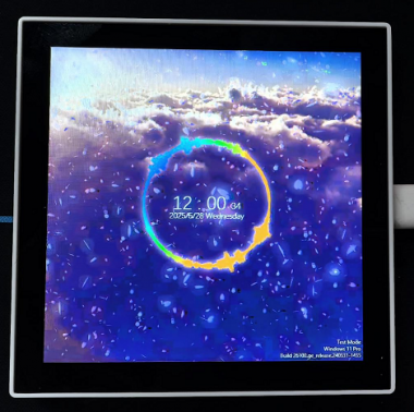
Windows Display Expansion
This example shows that ESP32-P4 expands Windows display through MIPI DSI interface and USB2.0 HS interface to support touch and audio. It fully demonstrates the powerful image, USB2.0 HS, and image decoding capabilities of ESP32-P4
Hardware Required
- ESP32-P4-86-Panel-ETH-2RO
- Type-A TO Type-A adapter cable
- Speaker
Software Driver
- Driver installation reference: Windows IDD Driver
Flashing Effect
Expert Techniques
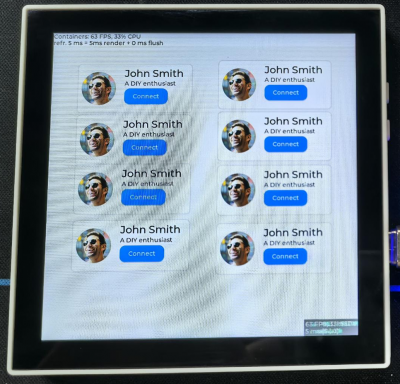
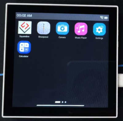
ESP-Phone
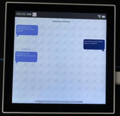
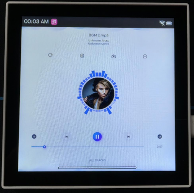
This example is based on ESP_Brookesia and shows an Android-like interface with many different applications. This example uses the board's MIPI-DSI port, MIPI-CSI port, ESP32-C6, TF card, and audio jack. Based on this example, you can create a use case based on ESP_Brookesia to efficiently develop multimedia applications.
Hardware Required
- OV5647 or SC2336 camera and cable
- 8Ω 2W speaker
- ESP32-P4-86-Panel-ETH-2RO
Screen Wake-Up Steps
- After opening the project, select
esp32p4core, and you can directly click to compile, flash, monitor. Upon completion, you can view the screen:
Expansion Board Control
Ethernet demo
Basic Concepts of Ethernet
- Ethernet is an asynchronous Carrier Sense Multiple Access with Collision Detection (CSMA/CD) protocol or interface. Generally speaking, Ethernet is not suitable for low-power applications. However, thanks to its wide range of deployments, efficient network connectivity, high data rates, and unlimited scalability, almost all wired communication can be carried over Ethernet. Currently, Ethernet is classified based on speed tiers as follows: standard Ethernet (10Mbit/s), fast Ethernet (100Mbit/s), gigabit Ethernet (1000Mbit/s), and faster ten-gigabit Ethernet (10Gbit/s).
- Ethernet port types include RJ45 port, RJ11 port (telephone jack), etc. The RJ45 port is the most commonly used Ethernet port (computer port), and it is also the ESP32-P4-NANO onboard network port type.
- ESP32-P4-86-Panel-ETH-2RO can be explained by referencing the network model:
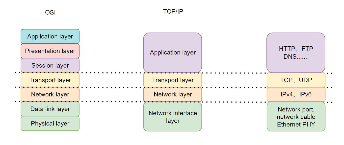
- ESP32-P4-86-Panel-ETH-2RO network interface layer: ESP32-P4 is connected to the IP101GRI through the RMII interface, and the RJ45 Ethernet port is drawn through the network transformer, while the development board is managed by the MAC layer integrated into the ESP32-P4 chip for the encapsulation, checksum and MAC address of the data frame.
- ESP32-P4-86-Panel-ETH-2ROO network layer and transport layer: Implemented by the ESP32-P4 driving the IP101GRI
- ESP32-P4-NANO application layer: When a connection is successfully established with the network, ESP32-P4 can implement HTTP requests and use communication servers such as MQTT.
Example Demonstration
This example demonstrates the basic usage of Ethernet driver and esp_netif. The initialization of the Ethernet driver is included in a separate subcomponent of the project to clearly distinguish between the initialization of the driver and the initialization of the esp_netif. The workflow for this example is as follows: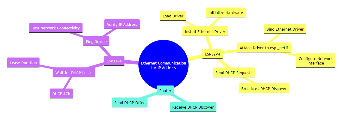
- RMII definition:
As mentioned above, the ESP32-P4-86-Panel-ETH-2RO is connected with the IP101 GRI chip through RMII interface, and the interface is defined as follows:TXD[1:0]: Sending data cable, controlled by GPIO34 and GPIO35RXD[1:0]: Receiving data cable, controlled by GPIO30 and GPIO29TX_EN: Sends an enable signal, controlled by GPIO49CRS_DV: Carrier detection and data valid signals, controlled by GPIO28REF_CLK: Reference clock, controlled by GPIO50, 50MHz generated by a 25 MHz passive crystal oscillator connected outside the PHY through frequency doublingMDIOandMDC: Manage data interface for Ethernet (control and configuration of the PHY) is controlled by GPIO52 and GPIO31RESET: Control IP101GRI reset, controlled by GPIO51
- Open the
ethernetbasicproject, select the appropriate COM port and chip model, click on the to enter the settings. This will open a new tab: SDK Configuration editor, also known as menuconfig. Directly search for ETH in the search bar, you will find that the content has already been retrieved, and correspond to the parameters in the following figure: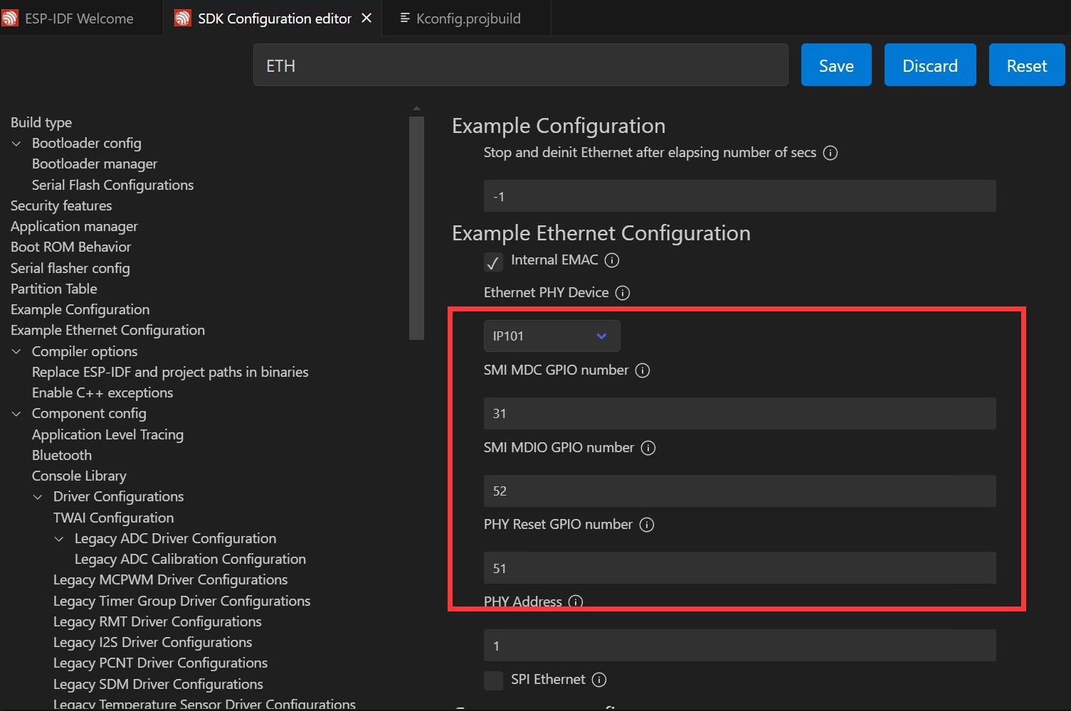
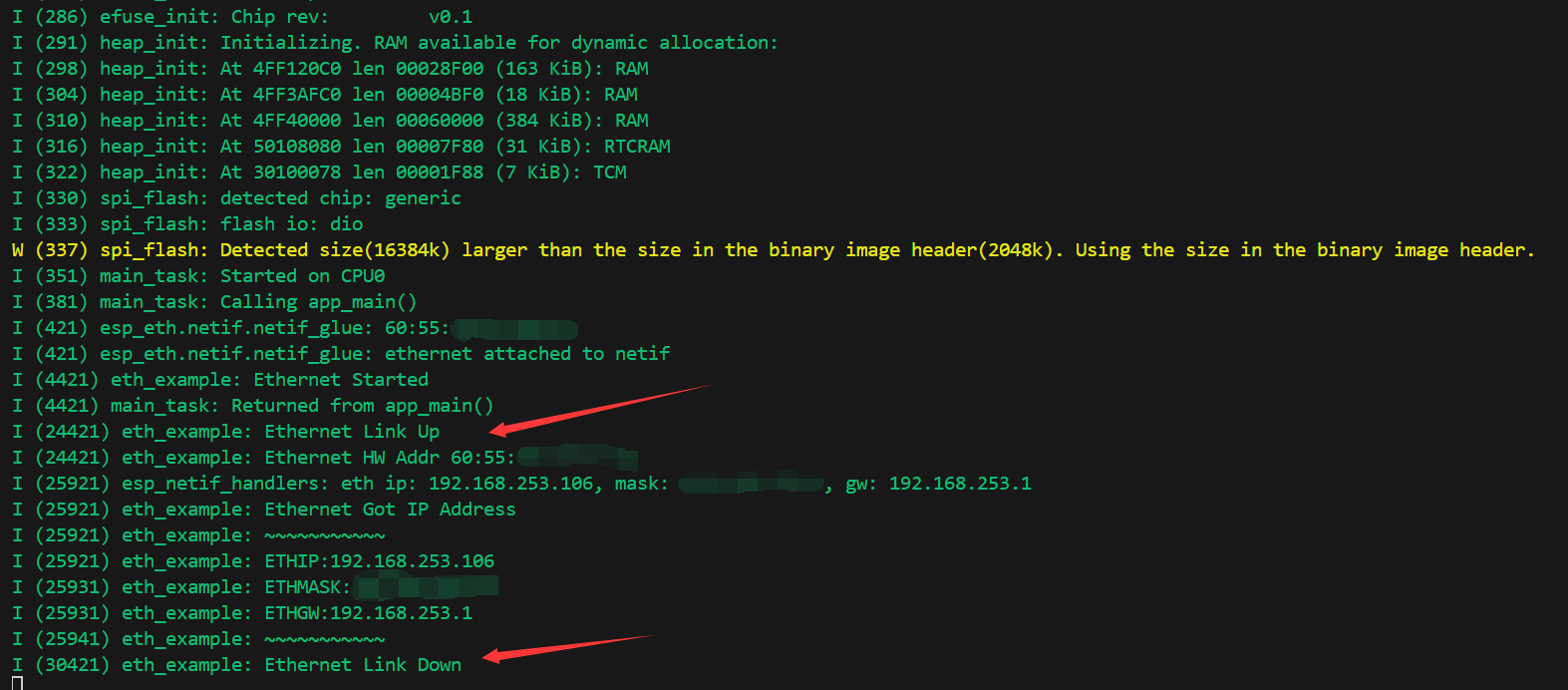
- Next, you can directly compile, flash, and monitor by clicking . Upon completion, you will see the program start in the terminal. After inserting an Ethernet cable, you can obtain an IP address. Removing the cable will disconnect the action, as shown in the figure:
- You can see from the router that a device named
espressifis connected, and the ESP32-P4-86-Panel-ETH-2RO is connected to the network.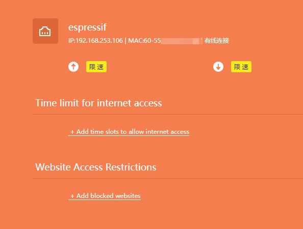
RS485 Control
RS485 Function in ESP32-P4
- The ESP32-P4 has a Universal Asynchronous Receiver/Transmitter (UART) function that handles communication timing requirements and data frames by using common asynchronous serial communication interfaces such as RS232, RS422, RS485, etc.
- The ESP32-P4 has 5 UART controllers that can be independently configured for baud rate, data bit length, bit order, number of stop bits, parity bits, etc.
- The GPIO switch matrix and IO MUX of the ESP32-P4 can configure input signals of the peripheral modules to come from any IO pin, and the output signals of the peripheral modules can also be connected to any IO pin. Here RS485 controls RXD: GPIO48, TXD: GPIO47
Example Demonstration
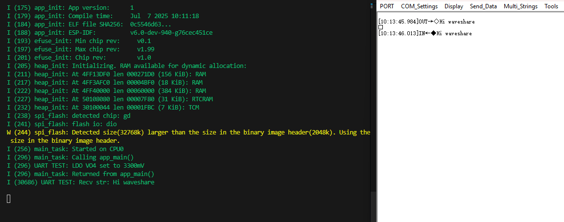
This example demonstrates an example of RS485 communication on the ESP32-P4. The workflow for this example is as follows:
- Control the voltage of LDO VO4 to 3.3V. As the voltage domains of GPIO47 and GPIO48 are controlled by LDO VO4, it is necessary to set an appropriate UART communication voltage; This setting will not interfere with the TF card of SDIO3.0
- Initialize UART1 port and set communication parameters
- Create a UART data loopback task to return the received data unchanged
- Print debugging information through the ESP_LOG system
Relay Control
The expansion board in ESP32-P4-86-Panel-ETH-2RO expands two relays, which are controlled by GPIO32 and GPIO46 respectively. Control of the relays can be achieved by simply controlling the IO output high or low levels
Resources
Schematic Diagrams
Demo
Datasheets
Software
FAQ
Support
Monday-Friday (9:30-6:30) Saturday (9:30-5:30)
Email: services01@spotpear.com
[Tutorial Navigation]
- Overview
- Version Description
- Usage Instructions
- Arduino
- ESP-IDF
- Introduction to ESP-IDF and Environment Setup (VSCode Column)
- Getting Start
- Intermediate
- Advanced
- Expert Techniques
- Expansion Board Control
- Resources
- FAQ
- Support