


- sales/support
Google Chat:---
- sales
+86-0755-88291180
- sales01
sales@spotpear.com
- sales02
dragon_manager@163.com
- support
tech-support@spotpear.com
- CEO-Complaints
zhoujie@spotpear.com
- Only Tech-Support
WhatsApp:13246739196
- Purchase/Shipping/Refund
WhatsApp:13424403025
Raspberry Pi RP2040-Zero User Guide
Overview
RP2040-Zero, A Low-Cost, High-Performance Pico-Like MCU Board Based On Raspberry Pi Microcontroller RP2040
Specification
- RP2040 microcontroller chip designed by Raspberry Pi in the United Kingdom
- Dual-core Arm Cortex M0+ processor, flexible clock running up to 133 MHz
- 264KB of SRAM, and 2MB of on-board Flash memory
- USB-C connector, keeps it up to date, easier to use
- The castellated module allows soldering direct to carrier boards
- USB 1.1 with device and host support
- Low-power sleep and dormant modes
- Drag-and-drop programming using mass storage over USB
- 29 × multi-function GPIO pins (20× via edge pinout, others via solder points)
- 2 × SPI, 2 × I2C, 2 × UART, 4 × 12-bit ADC, 16 × controllable PWM channels
- Accurate clock and timer on-chip
- Temperature sensor
- Accelerated floating-point libraries on-chip
- 8 × Programmable I/O (PIO) state machines for custom peripheral support
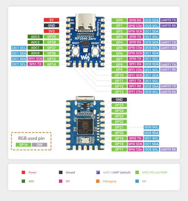
Pinouts
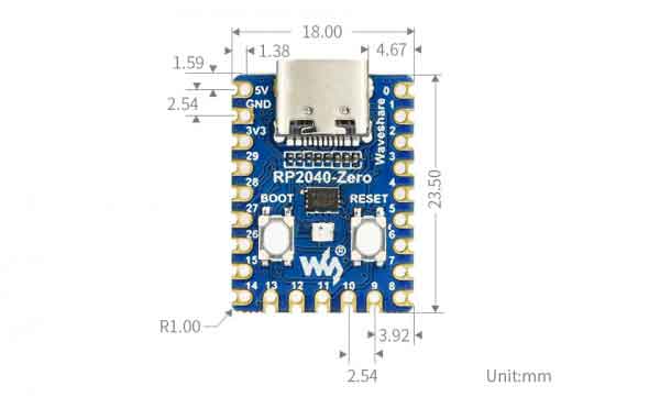
Dimension
Notice
RP2040-Zero uses the same RP2040 chip as the Raspberry Pi Pico, and it is compatible with the Raspberry Pi Pico, in this case, most of the accessories and codes can be used with the RP2040-LCD-0.96 as well.
Software Setup
Please follow the guides of Raspberry Pi to install and set up Pico for the Pico.
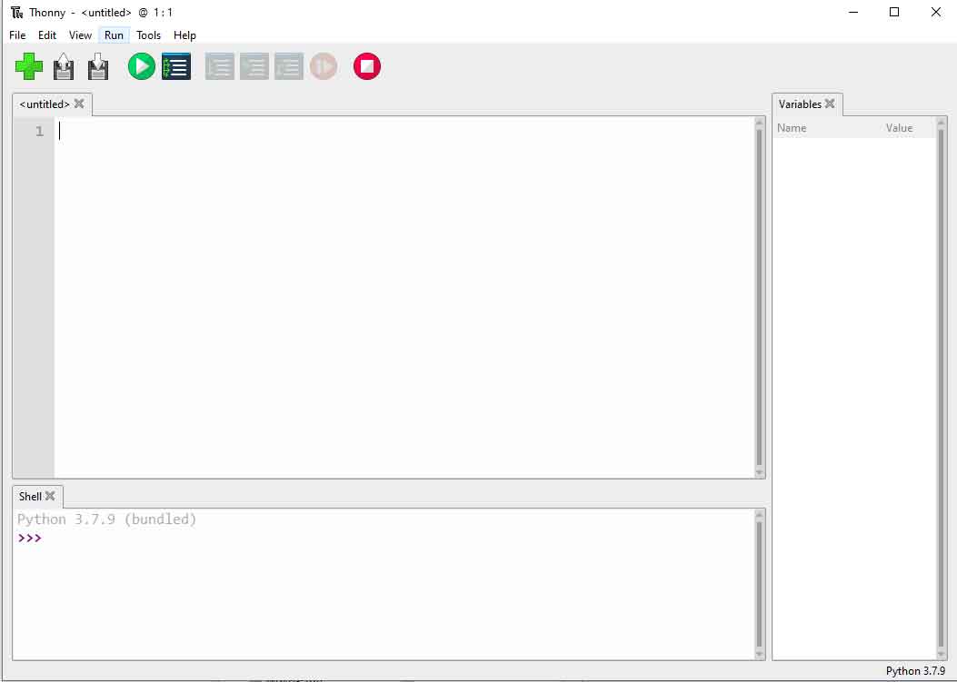
For easy use, we recommend you use the Thonny tool.
- Thonny website
- Please set the Thonny development environment to be RaspberryPi when setting
Examples
- Download Demo Codes to your Raspberry Pi and test.
External LED Example
Connect the boards as in the picture below. Connect the Pico to Raspberry Pi or PC. Open the Lesson-5 External LED example with Thonny. Run the example, and you will find that the red LED is flahsing.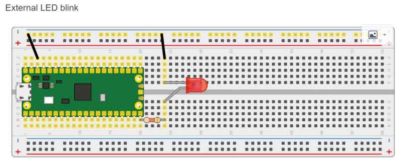
- Codes
led_external = machine.Pin(15, machine.Pin.OUT) #Set GP15 to output Mode
while True:
   led_external.toggle() #Toggle the LED every 5 seconds.
   utime.sleep(5)
Traffic Light System Examples
Connect the boards as in the picture below. Connect the Pico to Raspberry Pi or PC. Open the Lesson-9 Traffic-Light-System example by Thonny, run the codes and test the traffic light, the buzzer sounds when you press the button.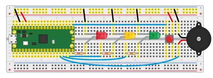
- Codes
def button_reader_thread():  #Check if the button is pressed
   global button_pressed
   while True:
       if button.value() == 1:
           button_pressed = True

_thread.start_new_thread(button_reader_thread, ()) #Start a new thread to monitor the stats of button
while True:
   if button_pressed == True: #If the button is pressed, turn on the LED and let the buzzer work.
       led_red.value(1)
       for i in range(10):
           buzzer.value(1)
           utime.sleep(0.2)
           buzzer.value(0)
           utime.sleep(0.2)
       global button_pressed
       button_pressed = False
   led_red.value(1)
   utime.sleep(5)
   led_amber.value(1)
   utime.sleep(2)
   led_red.value(0)
   led_amber.value(0)
   led_green.value(1)
   utime.sleep(5)
   led_green.value(0)
   led_amber.value(1)
   utime.sleep(5)
   led_amber.value(0)
Burglar Alarm LED Buzzer Examples
Connect the boards as in the picture below. Connect the Pico to Raspberry Pi or PC. Open the Lesson-14 Burglar Alarm LED Buzzer examples by Thonny.The LED lights on if an object is moving around the Passive infrared sensor and the buzzer will indicate.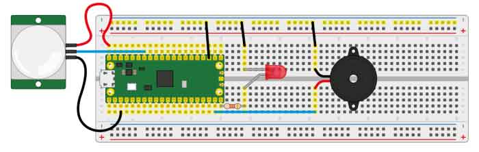
- Codes
def pir_handler(pin):  #Interrupt process function
   print("ALARM! Motion detected!")
   for i in range(50):
       led.toggle()
       buzzer.toggle()
       utime.sleep_ms(100)
sensor_pir.irq(trigger=machine.Pin.IRQ_RISING, handler=pir_handler)#Enable the Interrupt, the interrupt function is called when motions is detected.
while True:  #Toggle LED every 5s
   led.toggle()
   utime.sleep(5)
Potentiometer Example
Connect the boards as in the picture below. Connect the Pico to Raspberry Pi or PC. Open the Lesson-16 Potentiometer example by Thonny, you can adjust the potentiometer and check if the voltage printed to the Sheel window are changing as well.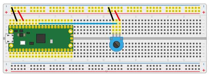
- Codes
potentiometer = machine.ADC(26) #Set the GP26 pin as analog input
conversion_factor = 3.3 / (65535)
while True:
   voltage = potentiometer.read_u16() * conversion_factor #Convert the sampled data to voltage value
   print(voltage) #Print the voltage data, it chanaged according to the sliding rheostat.
   utime.sleep(2)
WS2812 Example
Connect the boards as in the picture below. Connect the Pico to Raspberry Pi or PC. Open the WS2812_RGB_LED.py file of Lesson-25 WS2812 example by Thonny, the LEDs light in Blue, Red, Green, and White.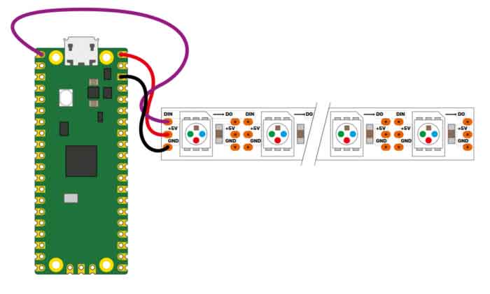
- Codes
#This code uses the state machine mechanism. The following code is a decorator where we can initialize the hardware, set the pin level, etc.
#label("bitloop") We can define some tags in our code so that we can jump to them.
#jmp(not_x,"do_zero") If x=0, we jumpt to do_zero.
#nop() .set(0) [T2 - 1] The code jumpt to here if x = 0.
@asm_pio(sideset_init=PIO.OUT_LOW, out_shiftdir=PIO.SHIFT_LEFT, autopull=True, pull_thresh=24)
def ws2812():
   T1 = 2
   T2 = 5
   T3 = 1
   label("bitloop")
   out(x, 1)               .side(0)    [T3 - 1]
   jmp(not_x, "do_zero")   .side(1)    [T1 - 1]
   jmp("bitloop")          .side(1)    [T2 - 1]
   label("do_zero")
   nop()                   .side(0)    [T2 - 1]
# Create the StateMachine with the ws2812 program, outputting on Pin(22).
sm = StateMachine(0, ws2812, freq=8000000, sideset_base=Pin(0)) #Create the stats machine
# Start the StateMachine, it will wait for data on its FIFO.
sm.active(1) #Start the stats machine
# Display a pattern on the LEDs via an array of LED RGB values.
ar = array.array("I", [0 for _ in range(NUM_LEDS)])
print(ar)
print("blue")
for j in range(0, 255):
   for i in range(NUM_LEDS):
       ar[i] = j
   sm.put(ar,8)  #put() is put the data to output FIFO of the stats machine
   time.sleep_ms(5)
LCD1602 I2C Example
Connect the boards as in the picture below. Connect the Pico to Raspberry Pi or PC. Open the Lesson-21 LCD1602 I2C example by Thonny, you need to first save the RGB1602.py to Pico and then run the Choose_Color.py file. The LCD will change color every 5s. If you run the Discoloratio.py file, the LED display RGB colors. 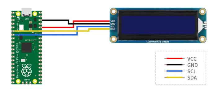
- Codes
Choose_Color.py
#Define colors
rgb9 = (0,255,0) #green
lcd.setCursor(0, 0) #Set the position of cursor
# print the number of seconds since reset:
lcd.printout("Waveshare") #Print the string
lcd.setCursor(0, 1) #Move the cursor to second row.
lcd.printout("Hello,World!")#Print the string
lcd.setRGB(rgb1[0],rgb1[1],rgb1[2]); #Set the back light
Discoloration.py
t=0
while True:

   r = int((abs(math.sin(3.14*t/180)))*255);  #RGB changeas as time goes
   g = int((abs(math.sin(3.14*(t+60)/180)))*255);
   b = int((abs(math.sin(3.14*(t+120)/180)))*255);
   t = t + 3;
   lcd.setRGB(r,g,b);#Set the RGB data again.
# set the cursor to column 0, line 1
   lcd.setCursor(0, 0) #Set the curson to the first row.
# print the number of seconds since reset:
   lcd.printout("Waveshare")#Print the string
   lcd.setCursor(0, 1) #Set the cursor to second row
   lcd.printout("Hello,World!")#Print the string
time.sleep(0.3) 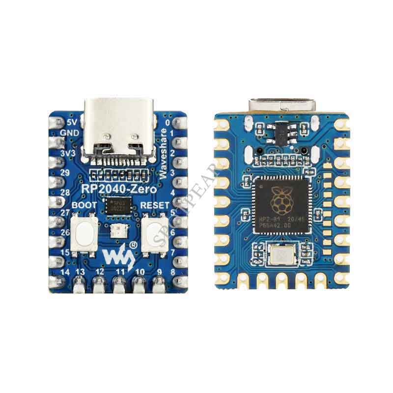