




- sales/support
Google Chat:---
- sales
+86-0755-88291180
- sales01
sales@spotpear.com
- sales02
dragon_manager@163.com
- support
tech-support@spotpear.com
- CEO-Complaints
zhoujie@spotpear.com
- Only Tech-Support
WhatsApp:13246739196
- Purchase/Shipping/Refund
WhatsApp:13424403025
- HOME
- >
- ARTICLES
- >
- Common Moudle
- >
- ESP
ESP32-C6-Touch-LCD-1.83 User Guide
Features
- Powered by the ESP32-C6 high-performance RISC-V 32-bit single-core processor, with a main frequency of up to 160 MHz
- Supports 2.4 GHz Wi-Fi 6 (802.11 b/g/n/ax), Bluetooth® 5 (LE), and IEEE 802.15.4 (supports Thread and Zigbee protocols), with optional onboard PCB antenna or external antenna connector
- Built-in 512 KB SRAM, 320 KB ROM, and 16 KB low-power SRAM, with support for external Flash (typically 4MB, 8MB, or 16MB)
- Features a Type-C interface, enhancing user convenience and device compatibility
- Onboard 1.83inch capacitive touch screen with 240 × 284 resolution and 65K colors
- Embedded with ST7789P driver chip and CST816D capacitive touch chip, communicating through SPI and I2C interfaces respectively, minimizes required IO pins
- Onboard QMI8658 six-axis inertial measurement unit (3-axis accelerometer, 3-axis gyroscope) for motion posture detection, step counting, etc.
- Onboard PCF85063 RTC chip, powered by the AXP2101 with battery backup for uninterrupted operation
- Onboard PWR and BOOT side buttons, configurable for custom function development
- Onboard 3.7V 1.2mm lithium battery charging/discharging interface
- Exposes 1-ch I2C, 1-ch USB and 1-ch UART pads for external devices connection and debugging, enabling flexible peripheral configuration
- Onboard TF card slot supporting storage expansion and high-speed data transfer, facilitating functions like data logging and media playback while simplifying circuit design
- The AXP2101 provides an efficient power management solution, supporting multiple configurable output voltages and integrating charging and battery management functions to help extend battery life
- Touch screen offers high transmittance, fast response, and long life
Onboard Resources
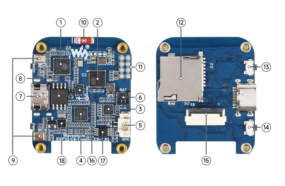
- ESP32-C6 supports Wi-Fi and Bluetooth SoC, operating at 160MHz
- AXP2101 Highly integrated power management chip
- ES8311 Low-power audio codec chip
- ES7210 ADC chip implements echo cancellation circuit
- MX1.25 Speaker Header Non-polarized
- 1.2mm Lithium battery header 1.2mm 2PIN connector for 3.7V Lithium battery, supports charging and discharging. The battery with 6 × 25 × 25 mm dimensions is recommended for installation inside the case.
- Type-C port USB port, for program flashing and log printing
- 16MB NOR-Flash for data storage
- Onboard Microphone Array Microphone input and echo cancellation
- Onboard Chip Antenna Supports 2.4GHz Wi-Fi (802.11 b/g/n) and Bluetooth 5 (LE)
- Reserved GPIO pads Adapting available I/O function pins for easy expansion
- TF Card Slot
- BOOT Button Used for device startup and functional debugging
- PWR button Long press for 6s to shut down, short press to power on, supports custom functions
- 1.83inch Display Panel Connector
- QMI8658 6-axis IMU includes a 3-axis gyroscope and a 3-axis accelerometer
- Speaker amplifier chip
- PCF85063 RTC clock chip
LCD and Its Controller
- The LCD uses the built-in ST7789P controller, which is a 240 × RGB × 320 pixel LCD controller. The LCD itself has a resolution of 240(H) × RGB × 284(V), so the internal RAM of the LCD is not fully used.
- The LCD supports 12-bit, 16-bit, and 18-bit per pixel input color formats, i.e., RGB444, RGB565, and RGB666. The examples use the RGB565 color format, which is the most common RGB format.
- The LCD uses a 4-wire SPI interface, which saves GPIO pins and also provides high communication speed.
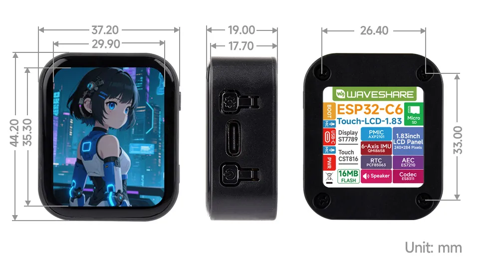
- The module resolution is 240(H) × RGB × 284(V), but because the four corners are rounded (see dimensions for details), some parts of an input image may not be displayed.
SPI Communication Protocol:
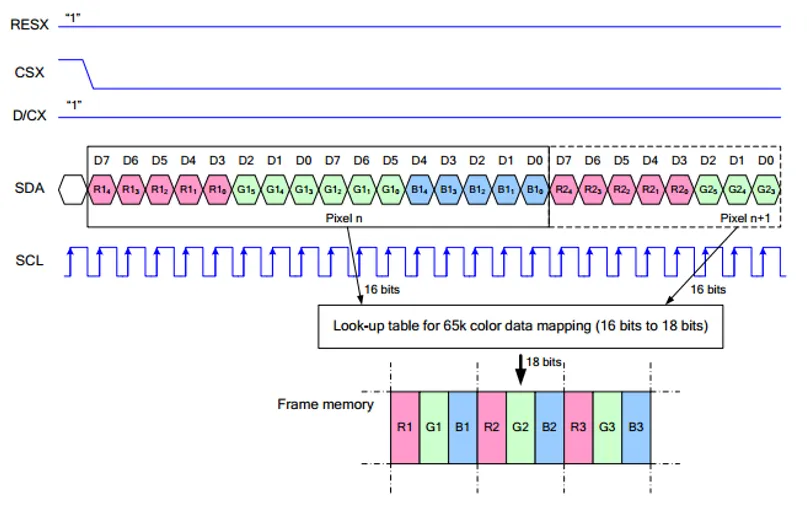
Note: The SPI interface here is specifically designed for screen display, therefore the data line from slave to master (MISO) is omitted.
RESX is the Reset pin; it is pulled low during module power-up and is normally set to 1.
CSX is the slave chip select pin; the chip is enabled only when CS is low
D/CX is the data/command control pin of the chip. When DC = 0, commands are written; when DC = 1, data is written.
SDA is the data transmission pin, specifically for RGB data.
SCL is the SPI communication clock pin.
For SPI communication, data transmission follows a specific timing sequence, which are determined by the combination of clock phase (CPHA) and clock polarity (CPOL):
The level of CPHA determines whether data is captured on the first or second clock transition edge of the serial synchronous clock. When CPHA = 0, data is captured on the first transition edge;
The level of CPOL determines the idle level of the serial synchronous clock. CPOL = 0 means the idle state is low level.
As can be seen from the diagram, data transmission begins at the first falling edge of SCL. One clock cycle transmits 1 bit of data, using SPI0 mode, transmitted bit by bit with the Most Significant Bit (MSB) first and the Least Significant Bit (LSB) last.
Touch and Its Controller
- This touch screen is equipped with CST816D self-capacitive touch control chip, supports the standard I2C communication protocol, and communication speed can be configured as 10Khz~400Khz.
Pinout Definition
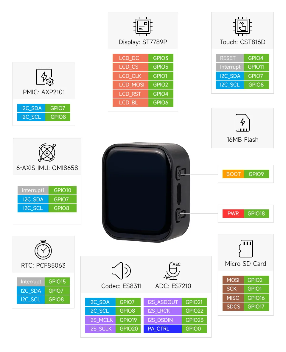
When using the GPIO pins reserved on the ESP32-C6-Touch-LCD-1.83 board, pay attention to the wire colors and corresponding functions to avoid burnout of the development board due to wiring habits
Dimensions
Working with Arduino
This chapter contains the following sections. Please read as needed:
Arduino Getting Started
New to Arduino ESP32 development and looking for a quick start? We have prepared a comprehensive Getting Started Tutorial for you.
- Section 0: Getting to Know ESP32
- Section 1: Installing and Configuring Arduino IDE
- Section 2: Arduino Basics
- Section 3: Digital Output/Input
- Section 4: Analog Input
- Section 5: Pulse Width Modulation (PWM)
- Section 6: Serial Communication (UART)
- Section 7: I2C Communication
- Section 8: SPI Communication
- Section 9: Wi-Fi Basics
- Section 10: Web Server
- Section 11: Bluetooth
- Section 12: LVGL GUI Development
- Section 13: Comprehensive Project
Note: This tutorial uses the ESP32-S3-Zero as a reference example, and all hardware code is based on its pinout. Before you start, we recommend checking the pinout of your development board to ensure the pin configuration is correct.
Setting Up the Development Environment
1. Installing and Configuring the Arduino IDE
Please refer to the tutorial Installing and Configuring Arduino IDE to download and install the Arduino IDE and add ESP32 support.
2. Installing Libraries
To run the example, you need to install the corresponding library. The example code uses the GFX Library for Arduino library to drive the ST7789 display and the Arduino_DriveBus library to drive the CST816 touch controller.
You can click this link to download the example package for the ESP32-C6-Touch-LCD-1.83 board from the Arduino directory. The Arduino\libraries directory within this package contains all the necessary library files required for this tutorial.
| Library or File Name | Description | Version | Installation Method |
|---|---|---|---|
| GFX Library for Arduino | ST7789 display driver graphics library | v1.6.0 | Install via library manager or manually |
| SensorLib | PCF85063, QMI8658 sensor driver library | v0.3.1 | Install via library manager or manually |
| XPowersLib | AXP2101 driver library | v0.3.0 | Install via library manager or manually |
| lvgl | LVGL display framework | v8.4.0 | Install via library manager or manually |
| Arduino_DriveBus | I2C, touch driver library | v1.0.1 | Install manually |
There are strong dependencies between versions of LVGL and its driver libraries. For example, a driver written for LVGL v8 may not be compatible with LVGL v9. To ensure that the examples can be reproduced reliably, it is recommended to use the specific versions listed in the table above. Mixing different versions of libraries may lead to compilation failures or runtime errors.
Installation Steps:
Download the example package.
Copy all folders (Arduino_DriveBus, GFX_Library_for_Arduino, etc.) in the
Arduino\librariesdirectory to the Arduino library folder.INFOThe path to the Arduino libraries folder is typically:
c:\Users\<username>\Documents\Arduino\libraries.You can also locate it in the Arduino IDE by going to File > Preferences and checking the "Sketchbook location". The libraries folder is the
librariessubfolder within this path.For other installation methods, please refer to: Arduino Library Management Tutorial.
3. Additional Tips
You need to select and configure the development board for ESP32-C6-Touch-LCD-1.83.
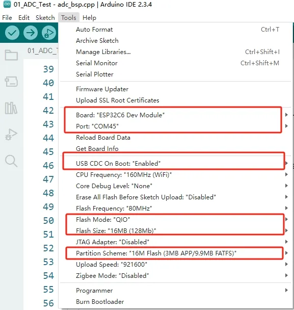
- The ESP32-C6-Touch-LCD-1.83 requires selecting ESP32S3 Dev Module.
- Select the USB port.
- The ESP32-C6-Touch-LCD-1.83 uses the ESP32-C6 native USB interface, not UART-to-USB. For serial communication:
The
printf()function can be used directly;To use the
Serial.println()function, additional configuration is required: Enable the "USB CDC On Boot" option in the IDE's Tools menu, or declare anHWCDCobject in your code to handle USB serial communication.
- Select 16MB Flash
- Select a Partition Table of the appropriate size
Example
The Arduino examples are located in the Arduino/examples directory of the example package.
| Example | Basic Description | Dependency Library |
|---|---|---|
| 01_sd_test | Demonstrates basic TF card mounting process, file read/write test | |
| 02_audio_out | Play MP3 audio | |
| 03_axp2101_example | Power management chip AXP2101 test | XPowersLib |
| 04_qmi8658_example | IMU QMI8658 test | SensorLib |
| 05_pcf85063_example | RTC real-time clock PCF85063 test | SensorLib |
| 06_gfx_helloworld | A simple ST7789 screen driver example | GFX_Library_for_Arduino |
| 07_LVGL_Arduino | LVGL v8.4 example program | Arduino_DriveBus, GFX_Library_for_Arduino, lvgl |
01_sd_test
This example demonstrates how to use SPI to mount a TF card and test file read/write operations
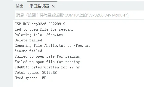
Code
01_sd_test.ino
Code Analysis
Initialize SPI and mount the TF card:
#ifdef REASSIGN_PINSSPI.begin(sck, miso, mosi, cs);if (!SD.begin(cs)) {#elseif (!SD.begin()) {#endifSerial.println("Card Mount Failed");return;}uint8_t cardType = SD.cardType();if (cardType == CARD_NONE) {Serial.println("No TF card attached");return;}Serial.print("TF Card Type: ");if (cardType == CARD_MMC) {Serial.println("MMC");} else if (cardType == CARD_SD) {Serial.println("SDSC");} else if (cardType == CARD_SDHC) {Serial.println("SDHC");}else{Serial.println("UNKNOWN");}uint64_t cardSize = SD.cardSize() / (1024 * 1024);Serial.printf("TF Card Size: %lluMB\n", cardSize);Test file read/write:
listDir(SD, "/", 0);createDir(SD, "/mydir");listDir(SD, "/", 0);removeDir(SD, "/mydir");listDir(SD, "/", 2);writeFile(SD, "/hello.txt", "Hello ");appendFile(SD, "/hello.txt", "World!\n");readFile(SD, "/hello.txt");deleteFile(SD, "/foo.txt");renameFile(SD, "/hello.txt", "/foo.txt");readFile(SD, "/foo.txt");testFileIO(SD, "/test.txt");Serial.printf("Total space: %lluMB\n", SD.totalBytes() / (1024 * 1024));Serial.printf("Used space: %lluMB\n", SD.usedBytes() / (1024 * 1024));
02_audio_out
This example demonstrates how to play audio using I2S. It has no display on the screen, and will automatically play audio after flashing
Code
02_audio_out.ino
Code Analysis
Initialize peripherals such as I2C, I2S, and configure the ES8311 decoder:
Serial.begin(115200);Wire.begin(I2C_SDA, I2C_SCL);es8311_codec_init();setupI2S();Serial.println("I2S Initialized");pinMode(PA_CTRL_PIN, OUTPUT);digitalWrite(PA_CTRL_PIN, HIGH);
03_axp2101_example
This example demonstrates how to use a power management chip and print battery-related information
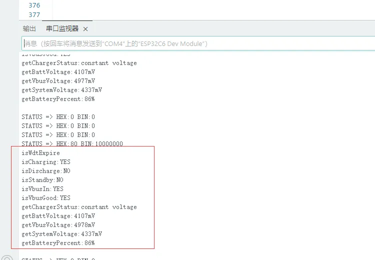
Code
03_axp2101_example.ino
Code Analysis
Initialize QMI8658:
bool result = power.begin(Wire, AXP2101_SLAVE_ADDRESS, i2c_sda, i2c_scl);
04_qmi8658_example
This example prints the running results of imu qmi8658
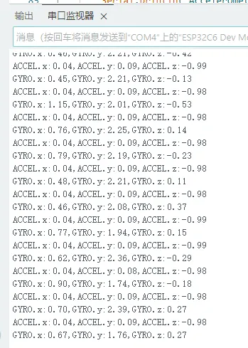
Code
04_qmi8658_example.ino
Code Analysis
Initialize qmi8658:
ret = qmi.begin(Wire, QMI8658_L_SLAVE_ADDRESS, SENSOR_SDA, SENSOR_SCL);
05_pcf85063_example
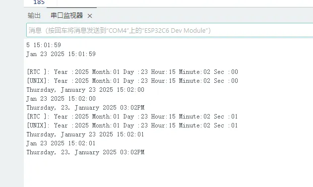
This example prints the value of RTC real-time clock pcf85063
Code
05_pcf85063_example.ino
Code Analysis
Initialize qmi8658:
if (!rtc.begin(Wire, SENSOR_SDA, SENSOR_SCL)) {Serial.println("Failed to find PCF85063 - check your wiring!");// Enter an infinite loop to halt the programwhile (1) {delay(1000);}}Set the time:
uint16_t year = 2023;uint8_t month = 9;uint8_t day = 7;uint8_t hour = 11;uint8_t minute = 24;uint8_t second = 30;// Set the defined date and time on the RTCrtc.setDateTime(year, month, day, hour, minute, second);
06_gfx_helloworld
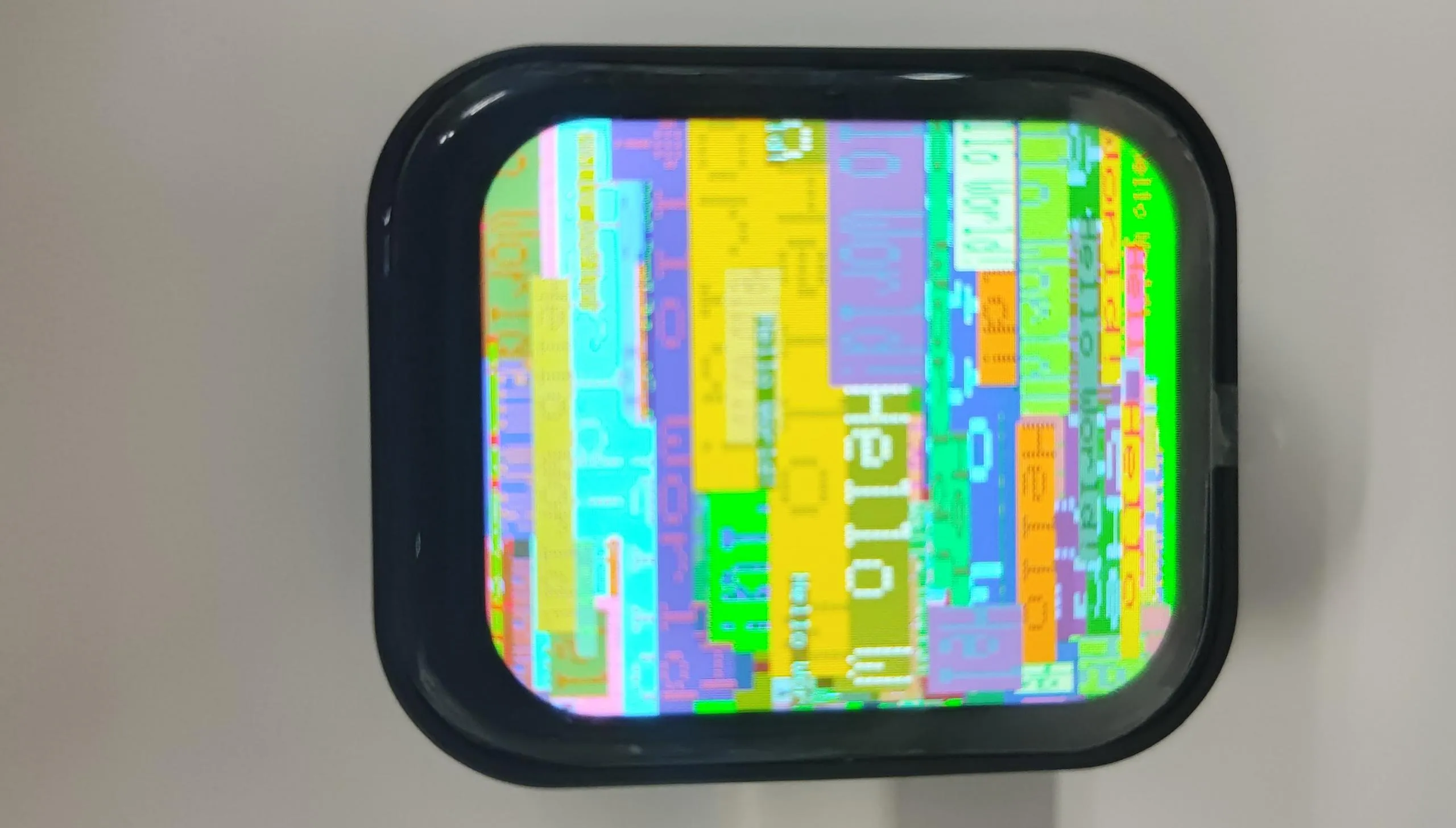
This example drives the screen and continuously prints "Hello World!" on the screen.
Code
06_gfx_helloworld.ino
Code Analysis
Initialize the SPI bus and the screen:
Arduino_DataBus *bus = new Arduino_HWSPI(LCD_DC, LCD_CS, LCD_SCK, LCD_DIN);Arduino_GFX *gfx = new Arduino_ST7789(bus, LCD_RST, 0 /* rotation */, true /* IPS */,240 /* width */, 284 /* height */);Fill with "Hello World":
gfx->setCursor(random(gfx->width()), random(gfx->height()));gfx->setTextColor(random(0xffff), random(0xffff));gfx->setTextSize(random(6) /* x scale */, random(6) /* y scale */, random(2) /* pixel_margin */);gfx->println("Hello World!");
07_LVGL_Arduino
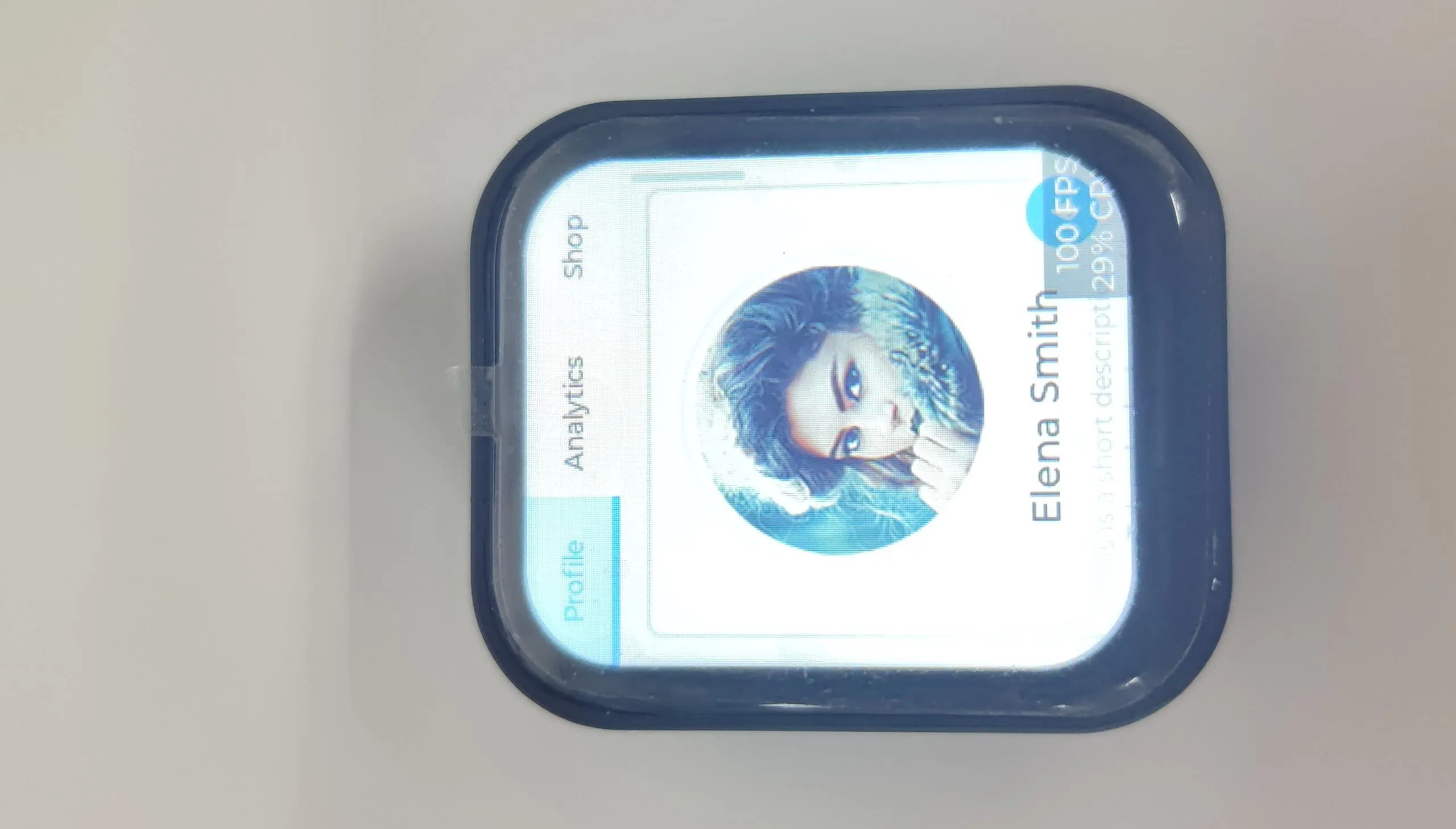
This example uses the Arduino_GFX_Library to drive the ST7789 screen, while porting LVGL and the touch driver
Code
07_LVGL_Arduino.ino
Code Analysis
Initialize the SPI bus and the screen:
Arduino_DataBus *bus = new Arduino_HWSPI(LCD_DC, LCD_CS, LCD_SCK, LCD_DIN);Arduino_GFX *gfx = new Arduino_ST7789(bus, LCD_RST, 0 /* rotation */, true /* IPS */,LCD_WIDTH /* width */, LCD_HEIGHT /* height */);Initialize the CST816 touch controller:
std::unique_ptr<Arduino_IIC> CST816T(new Arduino_CST816x(IIC_Bus, CST816T_DEVICE_ADDRESS,-1, TP_INT, Arduino_IIC_Touch_Interrupt));Initialize LVGL, configure the touch driver, and load the LVGL example program:
screenWidth = gfx->width();screenHeight = gfx->height();lv_init();lv_color_t *buf1 = (lv_color_t *)heap_caps_malloc(screenWidth * screenHeight / 4 * sizeof(lv_color_t), MALLOC_CAP_DMA);lv_color_t *buf2 = (lv_color_t *)heap_caps_malloc(screenWidth * screenHeight / 4 * sizeof(lv_color_t), MALLOC_CAP_DMA);String LVGL_Arduino = "Hello Arduino! ";LVGL_Arduino += String('V') + lv_version_major() + "." + lv_version_minor() + "." + lv_version_patch();USBSerial.println(LVGL_Arduino);USBSerial.println("I am LVGL_Arduino");#if LV_USE_LOG != 0lv_log_register_print_cb(my_print); /* register print function for debugging */#endiflv_disp_draw_buf_init(&draw_buf, buf1, buf2, screenWidth * screenHeight / 4);/*Initialize the display*/static lv_disp_drv_t disp_drv;lv_disp_drv_init(&disp_drv);/*Change the following line to your display resolution*/disp_drv.hor_res = screenWidth;disp_drv.ver_res = screenHeight;disp_drv.flush_cb = my_disp_flush;disp_drv.draw_buf = &draw_buf;lv_disp_drv_register(&disp_drv);/*Initialize the (dummy) input device driver*/static lv_indev_drv_t indev_drv;lv_indev_drv_init(&indev_drv);indev_drv.type = LV_INDEV_TYPE_POINTER;indev_drv.read_cb = my_touchpad_read;lv_indev_drv_register(&indev_drv);lv_obj_t *label = lv_label_create(lv_scr_act());lv_label_set_text(label, "Hello Ardino and LVGL!");lv_obj_align(label, LV_ALIGN_CENTER, 0, 0);const esp_timer_create_args_t lvgl_tick_timer_args = {.callback = &example_increase_lvgl_tick,.name = "lvgl_tick"};const esp_timer_create_args_t reboot_timer_args = {.callback = &example_increase_reboot,.name = "reboot"};esp_timer_handle_t lvgl_tick_timer = NULL;esp_timer_create(&lvgl_tick_timer_args, &lvgl_tick_timer);esp_timer_start_periodic(lvgl_tick_timer, EXAMPLE_LVGL_TICK_PERIOD_MS * 1000);lv_demo_widgets();
Working with ESP-IDF
This chapter includes the following sections, please read as needed:
ESP-IDF Getting Started
New to ESP32 ESP-IDF development and looking to get started quickly? We have prepared a general Getting Started Tutorial for you.
- Section 1: Environment Setup
- Section 2: Running Examples
- Section 3: Creating a Project
- Section 4: Using Components
- Section 5: Debugging
- Section 6: FreeRTOS
- Section 7: Peripherals
- Section 8: Wi-Fi Programming
- Section 9: BLE Programming
Please Note: This tutorial uses the ESP32-S3-Zero as a teaching example, and all hardware code is based on its pinout. Before you start, it is recommended that you check the pinout of your development board to ensure the pin configuration is correct.
Setting Up the Development Environment
The following guide uses Windows as an example, demonstrating development using VS Code + the ESP-IDF extension. macOS and Linux users should refer to the official documentation.
The screenshots in this section use ESP-IDF V5.5.2 as an example. When installing, please select the ESP-IDF version that matches your board's example.
Install the ESP-IDF Development Environment
Download the installation manager from the ESP-IDF Installation Manager page. This is Espressif's latest cross-platform installer. The following steps demonstrate how to use its offline installation feature.
Click the Offline Installer tab on the page, then select Windows as the operating system and the ESP-IDF version you need (the version shown in the screenshot is for reference only — choose the version that fits your actual needs).
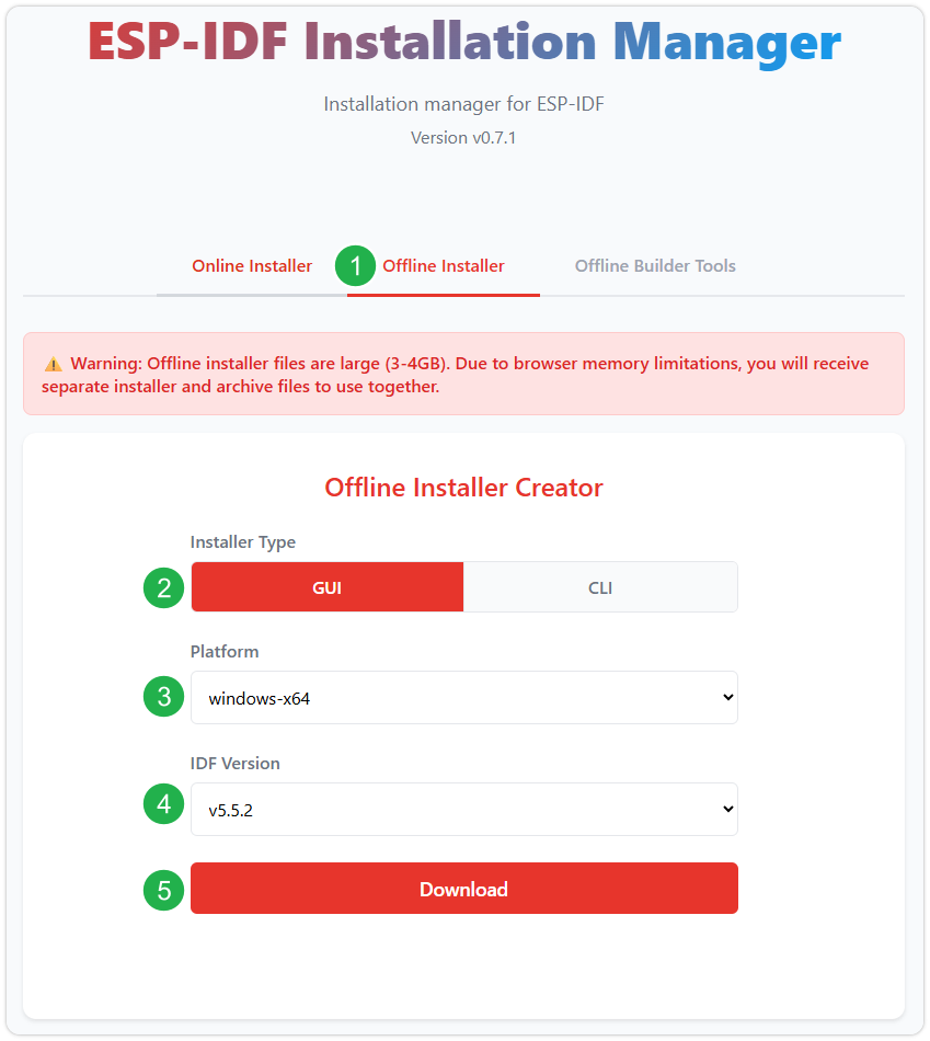
After confirming your selection, click the download button. The browser will automatically download two files: the ESP-IDF Offline Package (.zst) and the ESP-IDF Installer (.exe).
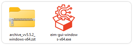
Please wait for both files to finish downloading.
Once the download is complete, double-click to run the ESP-IDF Installer (eim-gui-windows-x64.exe).
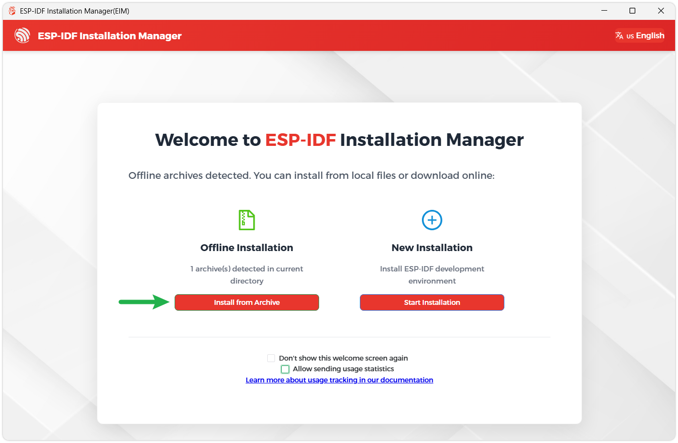
The installer will automatically detect if the offline package exists in the same directory. Click Install from archive.
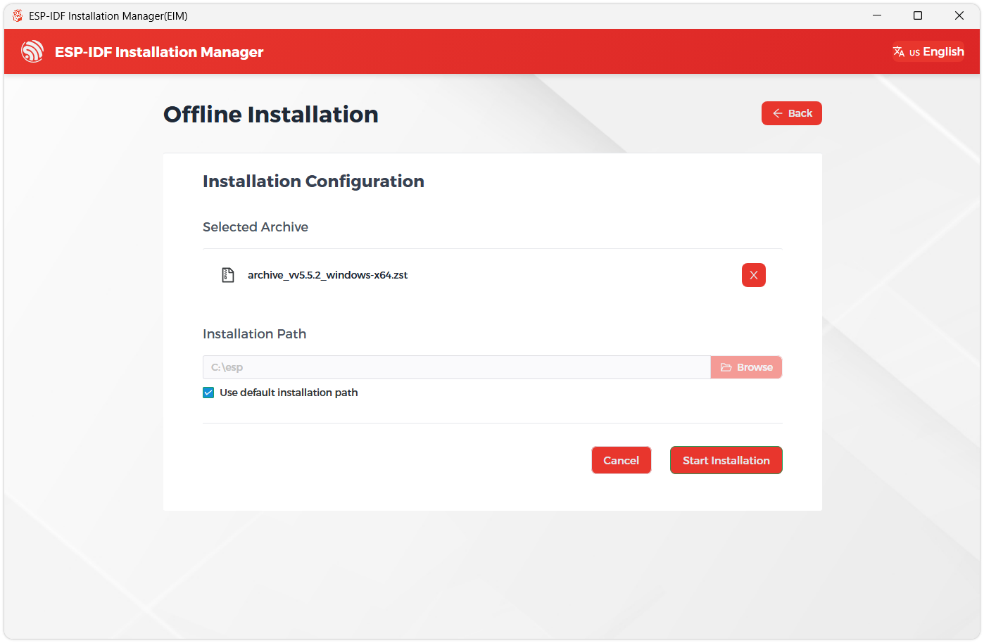
Next, select the installation path. We recommend using the default path. If you need to customize it, ensure the path does not contain Chinese characters or spaces. Click Start installation to proceed.
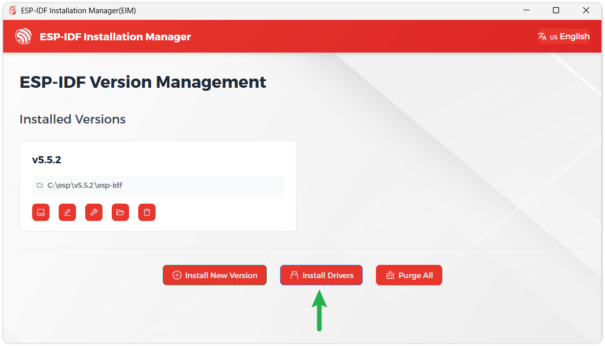
When you see the following screen, the ESP-IDF installation is successful.
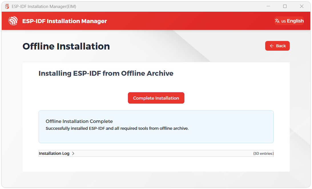
We recommend installing the drivers as well. Click Finish installation, then select Install driver.
Install Visual Studio Code and the ESP-IDF Extension
Download and install Visual Studio Code.
During installation, it is recommended to check Add "Open with Code" action to Windows Explorer file context menu to facilitate opening project folders quickly.
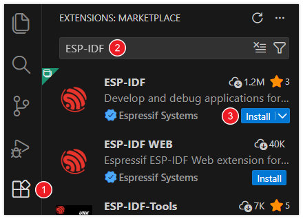
In VS Code, click the Extensions icon
 in the Activity Bar on the side (or use the shortcut Ctrl + Shift + X) to open the Extensions view.
Enter ESP-IDF in the search box, locate the ESP-IDF extension, and click Install.
For ESP-IDF extension versions ≥ 2.0, the extension will automatically detect and recognize the ESP-IDF environment installed in the previous steps, requiring no manual configuration.
Example
The ESP-IDF examples are located in the ESP-IDF directory of the example package.
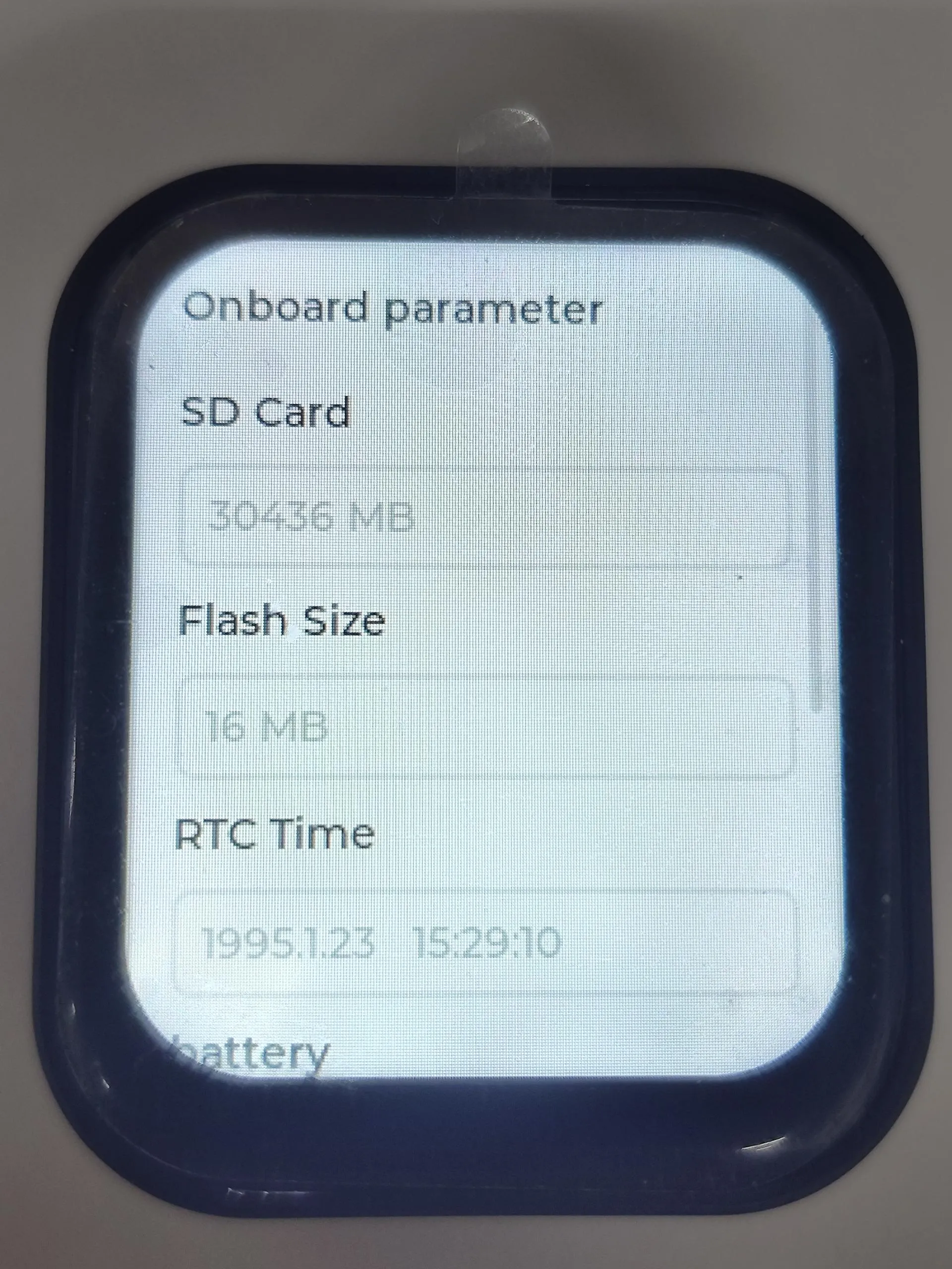
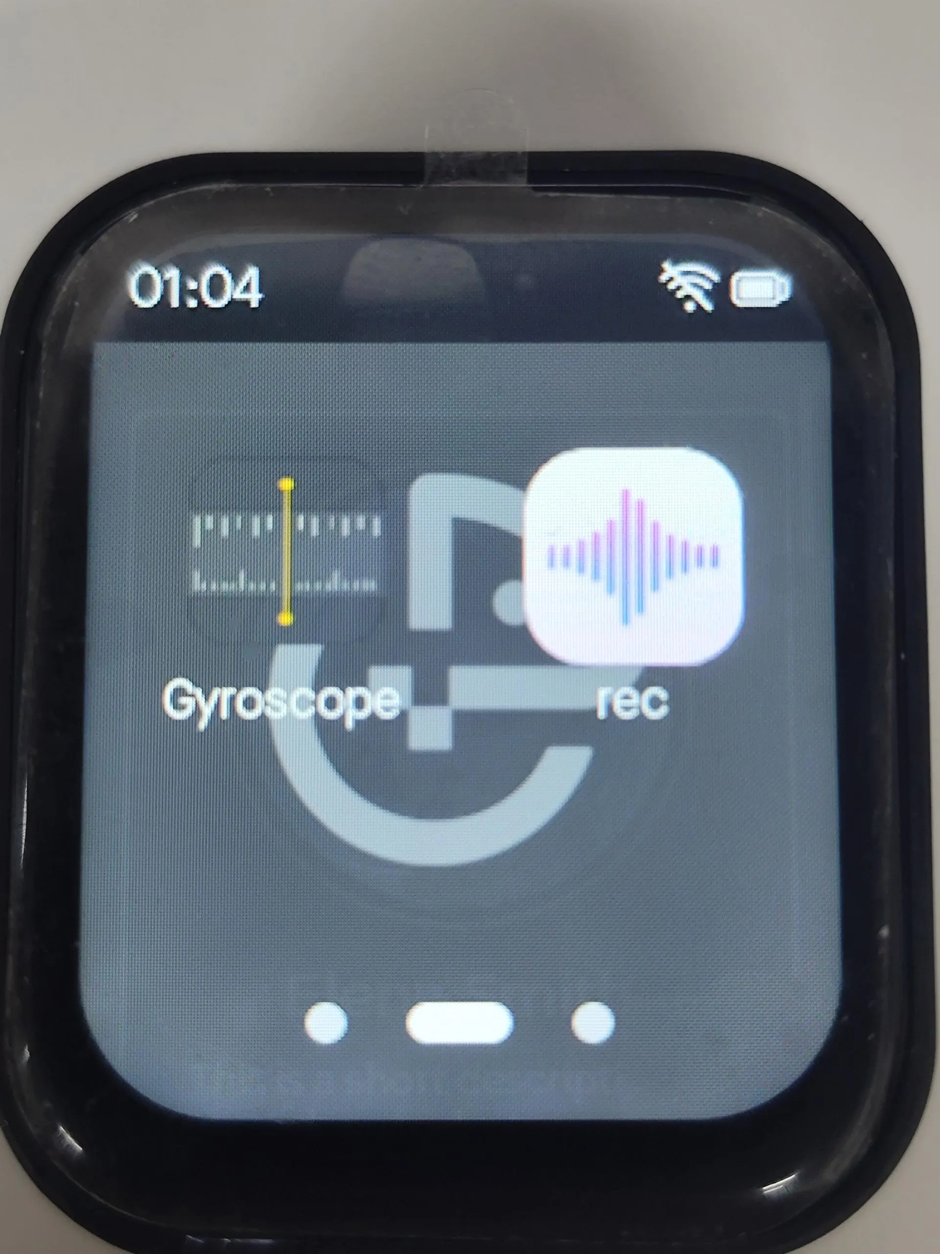
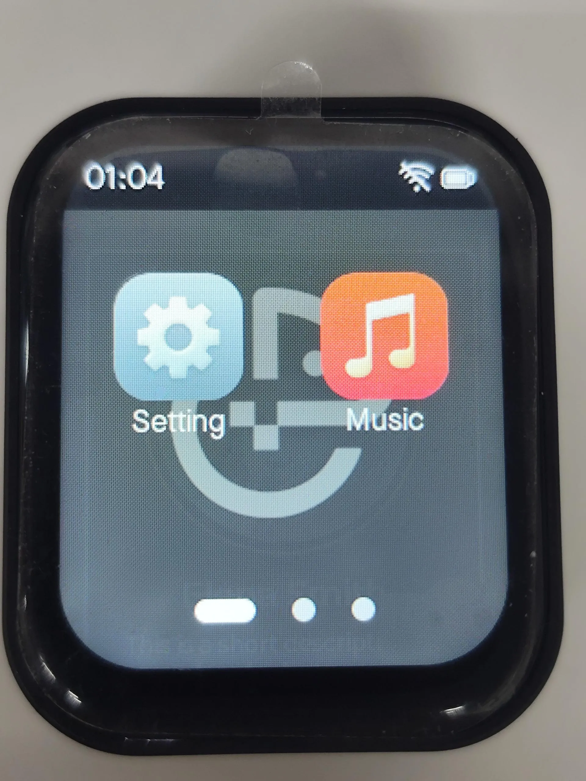
lvgl_brookesia_01
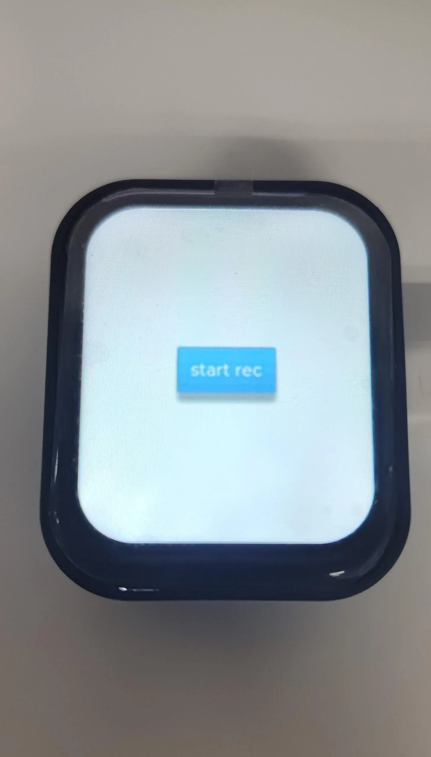
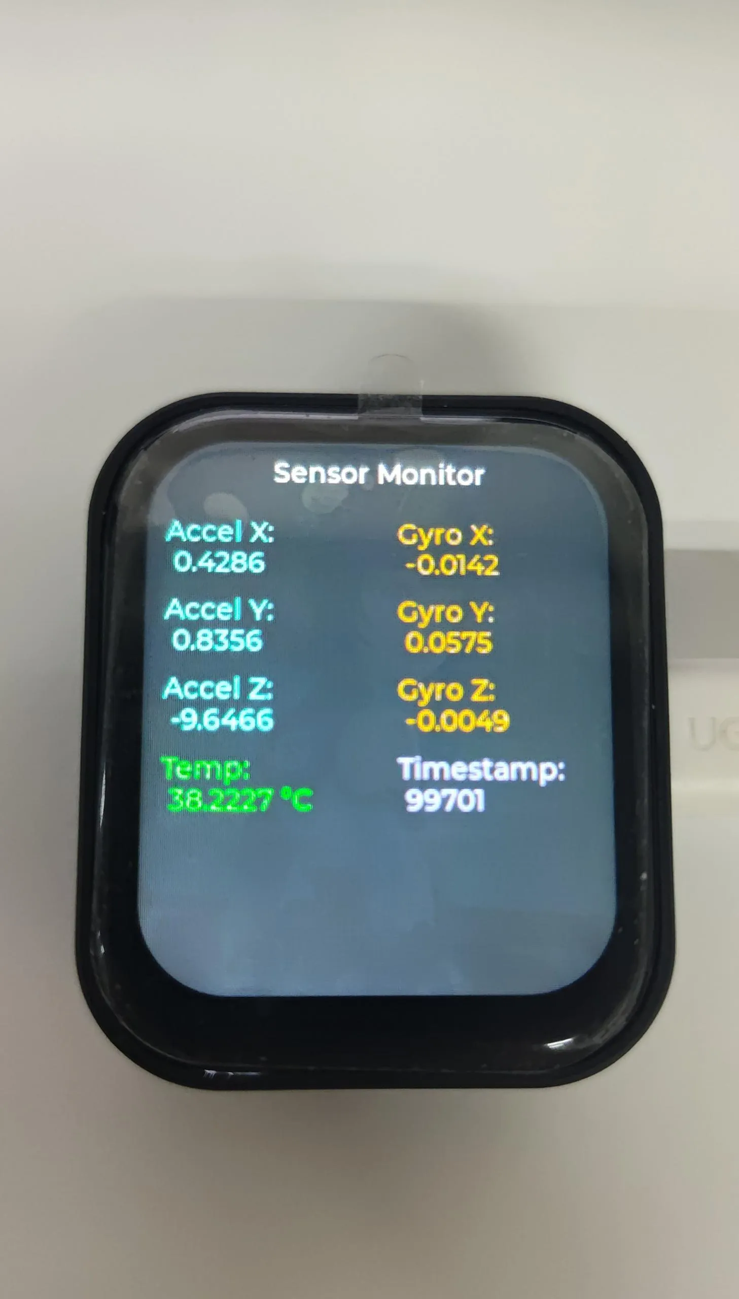
This example uses lvgl and brookesia components to build an APP-style interface that can be developed and installed independently for various applications.

i2s_es7210_rec_02
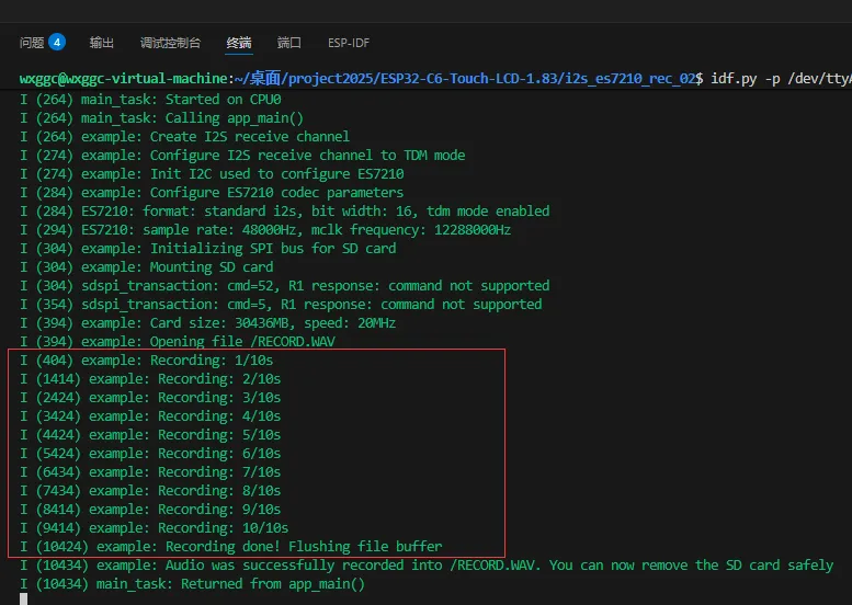
This example uses the ES7210 encoding chip for recording tests, and the audio file is stored in the root directory of the TF card.
Code Analysis
Initialize the TF card and the ES7210 chip:
/* Init I2C bus to configure ES7210 and I2S bus to receive audio data from ES7210 */i2s_chan_handle_t i2s_rx_chan = es7210_i2s_init();/* Create ES7210 device handle and configure codec parameters */es7210_codec_init();/* Mount TF card, the recorded audio file will be saved into it */sdmmc_card_t *sdmmc_card = mount_sdcard();Start recording:
esp_err_t err = record_wav(i2s_rx_chan);
mp3_play_03
This example uses ES8311 to play MP3 audio from the TF card, the audio name needs to be set to 1.MP3.
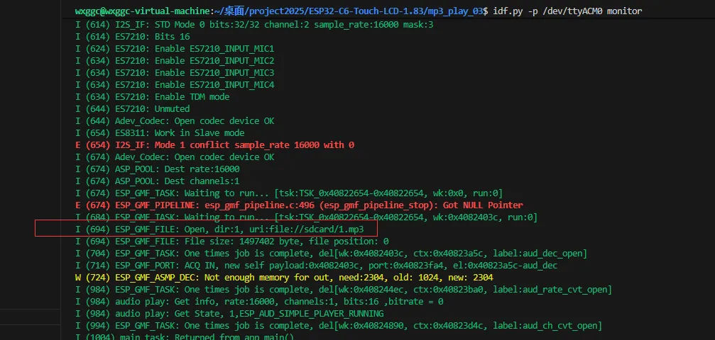
Code Analysis
Initialize the TF card and the ES8311 chip, and initialize the MP3 playback library:
sd_card_init();ESP_ERROR_CHECK(esp_board_init(16000, 1, 16));//esp_sdcard_init("/sdcard", 10);Audio_Play_Init();Play the MP3:
Audio_Play_Music("file://sdcard/1.mp3");
lvgl_example_04
This example ports LVGL and plays the LVGL example
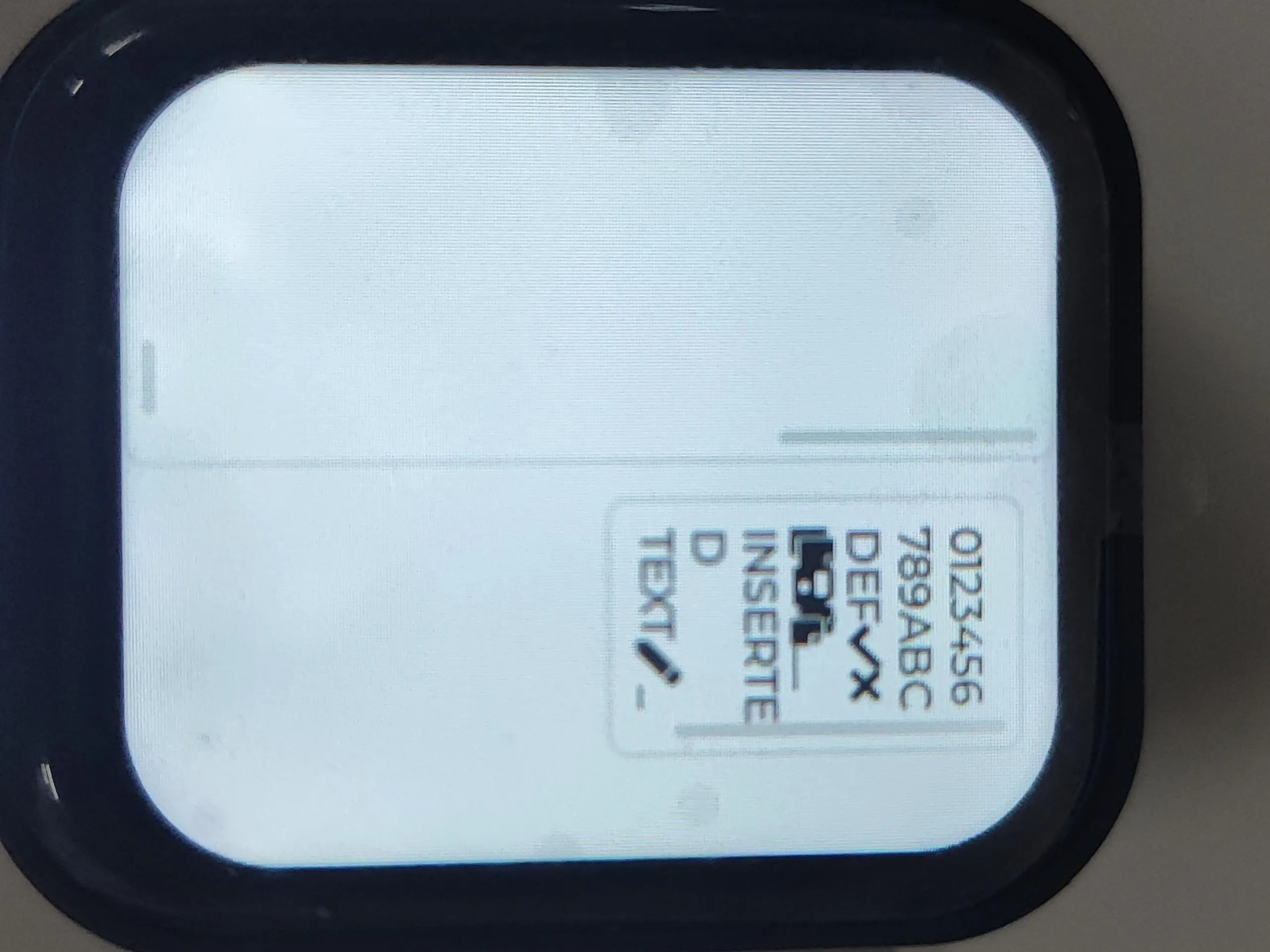
Code Analysis
Initialize I2C, LCD, touch IC, and LVGL:
i2c_master_init();lcd_driver_init();touch_driver_init();lvgl_driver_init();Use the LVGL mutex to load the official LVGL example:
lvgl_port_lock(0);lv_demo_stress();lvgl_port_unlock();
AXP2101_05
This example drives the AXP2101 and prints battery-related information
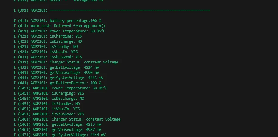
Code Analysis
Initialize I2C and the AXP2101:
ESP_ERROR_CHECK(i2c_init());ESP_LOGI(TAG, "I2C initialized successfully");ESP_ERROR_CHECK(pmu_init());Create a printing task:
xTaskCreate(pmu_hander_task, "App/pwr", 4 * 1024, NULL, 10, NULL);
lvgl_image_06
This example uses lvgl to display images, and you can switch between images by swiping left and right.
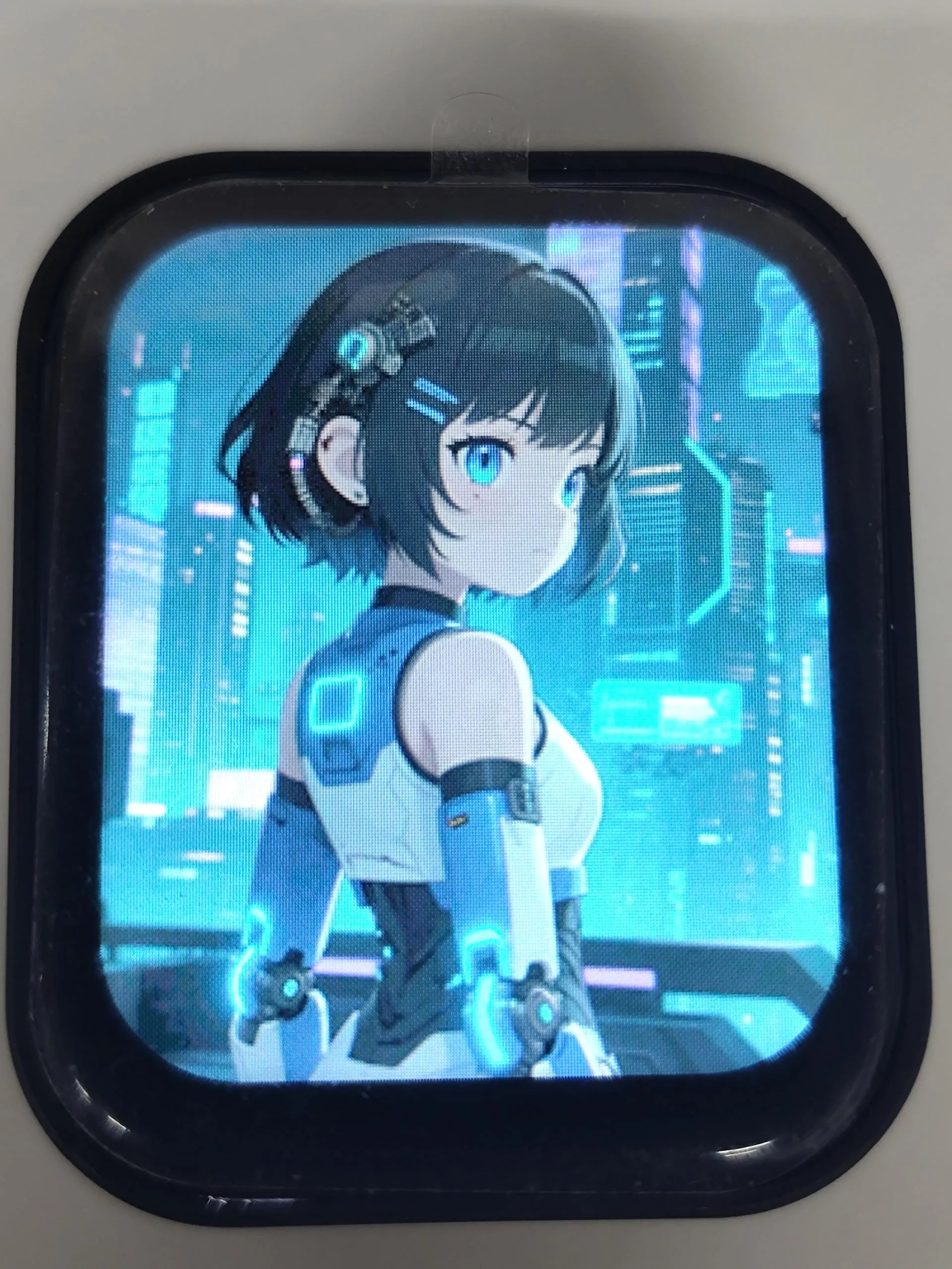
Code Analysis
Use the LVGL mutex to initialize image display:
lvgl_port_lock(0);image_slider_init();lvgl_port_unlock();
XiaoZhi AI Application Tutorial
XiaozhiAI (XiaoZhi AI) is an open-source AI voice chatbot project based on the ESP32 development board, aiming to bring the general intelligence of large language models (LLMs) to edge devices. It provides a software-hardware integrated solution supporting full-duplex voice conversations and IoT device control, dedicated to assisting developers in building highly customized physical AI agents quickly and at low cost.
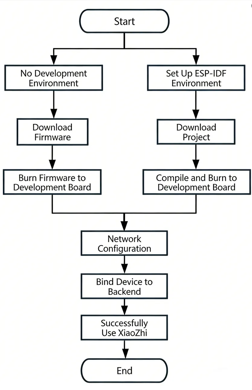
This article demonstrates how to flash firmware for Waveshare ESP32 development boards that support XiaoZhi AI, covering two methods: flashing without a development environment (directly flashing precompiled firmware) and flashing with a development environment (compiling from source and flashing).
0. Firmware Flashing Process Reference
This section uses the ESP32-S3-Touch-AMOLED-1.8 development board as an example. The steps are similar for other development boards.
Please first confirm that your hardware is listed in the XiaoZhi AI Supported Products List.
1. Flashing Without a Development Environment
1.1 Download Firmware from XiaoZhi Official GitHub
Visit the XiaoZhi GitHub to download the firmware file for your device. Click Assets to expand the full file list:
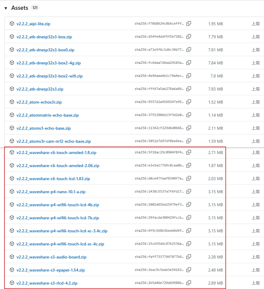
Refer to the Flash Firmware Flashing and Erasing Tutorial to complete the firmware flashing.
1.2 Download Firmware from Waveshare GitHub
This repository aggregates firmware for Waveshare ESP32 development boards that support XiaoZhi AI. All firmware has been tested and verified on the corresponding boards, making it convenient for users to find and download. Firmware versions may be updated slightly later than the official XiaoZhi repository.
Visit the Waveshare GitHub repository and download the appropriate firmware version for your needs:
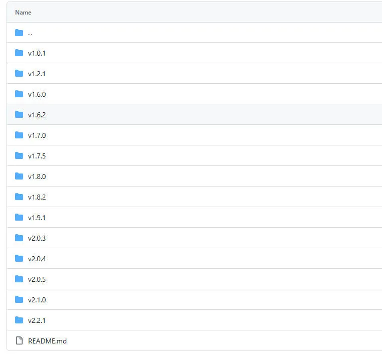
Refer to the Flash Firmware Flashing and Erasing Tutorial to complete the firmware flashing.
2. Flashing with ESP-IDF Environment
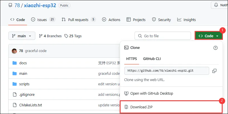
2.1 Download the Project from XiaoZhi GitHub
Visit the XiaoZhi AI Chatbot repository to download the complete project code:
2.2 Environment Setup
Refer to the ESP-IDF Environment Setup Tutorial to configure the development environment.
2.3 Configuration and Compilation
Click
 to select the target device. Choose the chip model corresponding to your development board (e.g.,
 esp32s3):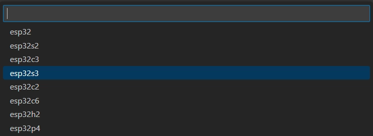 TIP
TIPWhen setting the target device, ESP-IDF will automatically configure the corresponding toolchain and libraries. This process may take some time, please be patient. For more details, please refer to the Official Documentation.
Click
 to open the ESP-IDF terminal, then execute the command
 idf.py menuconfigto enter the configuration interface. Select Xiaozhi Assistant: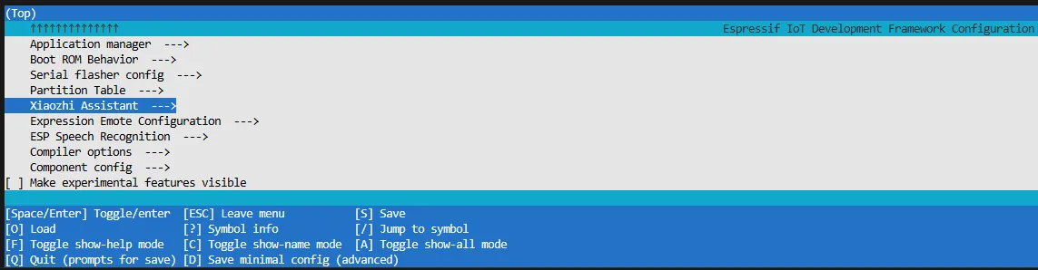
Select Board Type to choose the development board type:
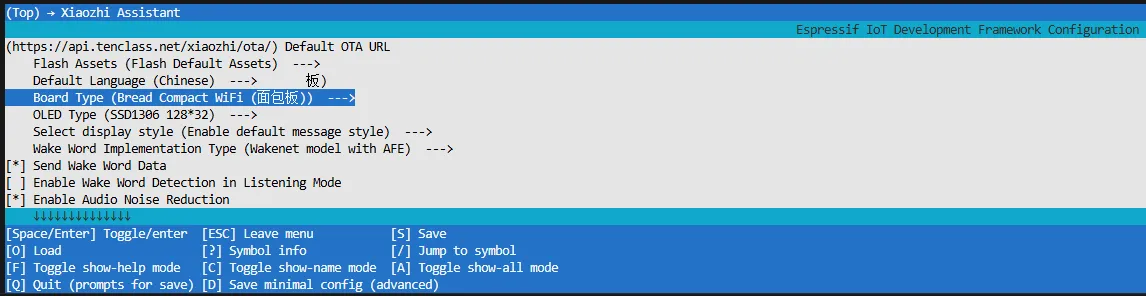
Choose the product model corresponding to your development board:
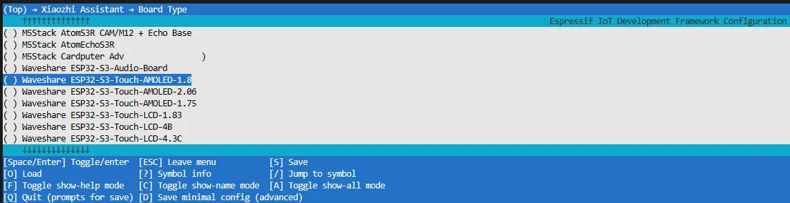
Press the S key to save the configuration and exit. Then click the
 to automatically complete compilation, flashing, and serial monitoring.
2.4 Start Network Provisioning
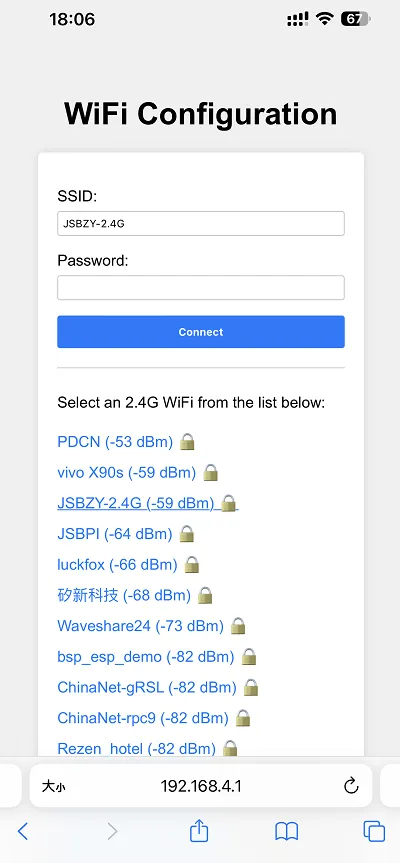
Connect your phone or computer to the device's Wi-Fi hotspot: Xiaozhi-xxxxxx. After successful connection, the configuration page should automatically pop up. If not, manually open a browser and visit
http://192.168.4.1.On the network configuration page, select the Wi-Fi name you want to connect to (only 2.4G band is supported; to connect to an iPhone hotspot, enable Max Compatibility in your phone's system settings). The SSID will be auto-filled. Enter the password and click Connect to start connecting:
2.5 Add a New Device to the Management Console
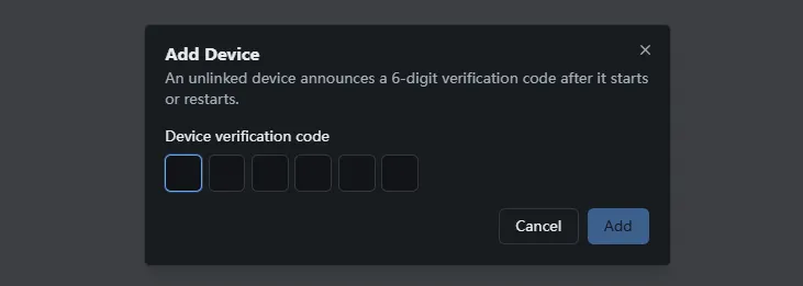
Ensure the device has successfully connected to the Internet. The device will then broadcast a 6-digit device verification code (you can wake the device again to replay the code).
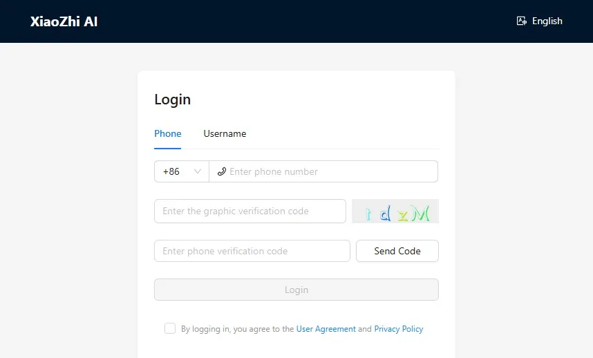
Visit the XiaoZhi AI Console. If you haven't registered, complete the registration and log in:
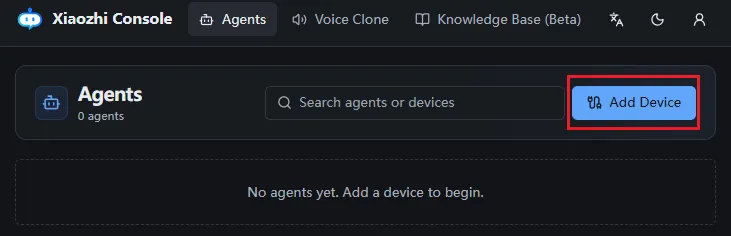
Enter the 6-digit verification code. The device will automatically activate and appear on the Device Management page, ready for normal use.
Say the wake word "Hello XiaoZhi" to wake the device and start voice conversations.
ESP32-S3-Touch-AMOLED-1.8 Button Instructions:
- BOOT button: Press to wake XiaoZhi
- PWR button: Short press to power on; long press for more than 6 seconds to power off
3. XiaoZhi Resources
Firmware Flashing and Erasing
This product provides test firmware that can be flashed directly to verify whether the onboard devices are functioning properly.
- Firmware download: ESP32-C6-Touch-LCD-1.83 Example. The bin file is located in the
ESP32-C6-Touch-LCD-1.83-Demo\Firmwaredirectory of the example package. - Flash address:
0x00
- Firmware Flashing
- Firmware Erasing
The following uses flashing the ESP32-S3-Touch-LCD-2.8 factory firmware as an example. The same steps apply when flashing other firmware.
Download and extract Espressif's official Flash Download Tool (Download)
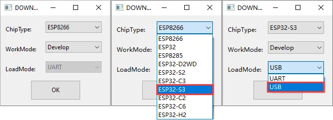
Run flash_download_tool_3.9.7.exe and select the development board's MCU and download interface, such as ESP32-S3 and USB (most devices use USB; refer to the product's hardware design for the correct interface).
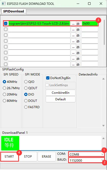
Parameter settings
- Select the COM port for the development board
- Set BAUD to the maximum value, 1152000
- Click the "..." button in the row, select the bin file provided by Waveshare, manually enter the flash address given at the top of this page in the field to its right, and select the leftmost checkbox in the row
- Click START to begin flashing
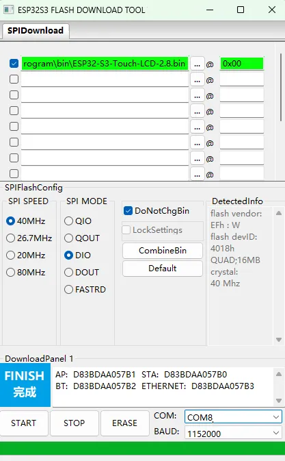
Wait for flashing to complete (this may take some time; please be patient)
Press the reset button and verify the result
Resources
1. Hardware Resources
Development Board Design Files
2. Technical Manuals
ESP32-C6 Chip Official Manuals
Datasheets
3. Example
Support
Monday-Friday (9:30-6:30) Saturday (9:30-5:30)
Email: services01@spotpear.com
[Tutorial Navigation]
- Features
- Onboard Resources
- Pinout Definition
- Dimensions
- Working with Arduino
- Working with ESP-IDF
- XiaoZhi AI Application Tutorial
- 0. Firmware Flashing Process Reference
- 1. Flashing Without a Development Environment
- 2. Flashing with ESP-IDF Environment
- 2.1 Download the Project from XiaoZhi GitHub
- 2.2 Environment Setup
- 2.3 Configuration and Compilation
- 2.4 Start Network Provisioning
- 2.5 Add a New Device to the Management Console
- 3. XiaoZhi Resources
- Firmware Flashing and Erasing
- Resources
- Support