


- sales/support
Google Chat:---
- sales
+86-0755-88291180
- sales01
sales@spotpear.com
- sales02
dragon_manager@163.com
- support
tech-support@spotpear.com
- CEO-Complaints
zhoujie@spotpear.com
- Only Tech-Support
WhatsApp:13246739196
- Purchase/Shipping/Refund
WhatsApp:13424403025
- HOME
- >
- ARTICLES
- >
- For Arduino
- >
- Mother Board
Arduino DUE User Guide
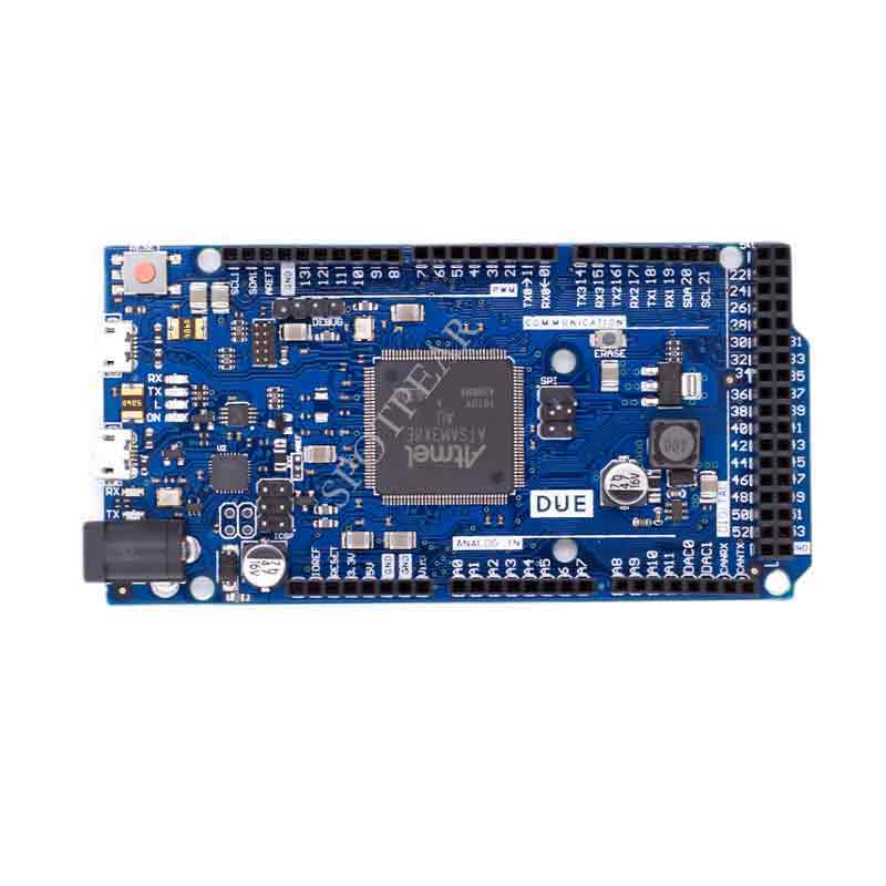
Overview
Arduino Due is a microcontroller board based on Atmel SAM3X8E CPU. It is the first arduino based on 32-bit ARM core. It has 54 digital IO ports (12 of which can be used for PWM output), 12 analog input ports, 4-way UART hardware serial port, 84 MHz clock frequency, one USB OTG interface, two-way DAC (analog-to-digital conversion), two-way TWI, one power socket, one SPI interface, one JTAG interface, one reset button and one erase button .
WARNING: Unlike other arduinos, the arduino due works at 3.3V. The loadable voltage of the IO port is also 3.3V. If you use a larger voltage, such as 5V to an IO port, it may burn the chip.
The circuit board already contains all the components needed to control the operation, you only need to connect to the computer via USB or connect the AC-DC adapter and battery to the power outlet to make the controller start to operate. Arduino due is compatible with arduino shields that operate at 3.3V and have a pinout that conforms to the 1.0 arduino standard.
Advantages of ARM cores
The Due with 32-bit ARM core is more powerful than other arduinos with 8-bit AVR core. The obvious differences are:
The 32-bit core can process 32-bit data in one clock;
84Mhz CPU clock frequency;
96 KBytes of SRAM;
512 KBytes of Flash;
A DMA controller, which can relieve the pressure of the CPU when doing a lot of calculations.
Schematics and Reference Designs
arduino-Due-reference-design.zip
Schematic: arduino-Due-schematic.pdf
Specifications
Microcontroller AT91SAM3X8E
Working Voltage Voltage 3.3V
Input voltage (recommended) 7-12V
Input voltage (limited) 6-20V
Digital I/O pins 54 (including 12 PWM outputs)
Analog input channel Pins 12
Analog Output Channel Pins 2 (DAC)
IO port total output current 130 mA
3.3V port output capability 800 mA
5V port output capability 800 mA
Flash 512 KB (all space can store user programs)
SRAM 96 KB (two parts: 64KB and 32KB)
Clock rate 84 MHz
Power supply
Arduino Due can be powered by Micro USB interface or external power supply, and the power supply can be selected automatically.
External (non-USB) power can be from an AC-DC adapter (wall-wart) or batteries. The adapter plugs into a 2.1mm power outlet with a positive center to connect to the controller power supply. The controller can support 6 to 20V voltage input. If the input voltage is lower than 7V, the 5V pin may get a voltage lower than 5V, and the controller operation may be unstable. If the input voltage exceeds 12V, it may cause the controller to overheat or even be damaged. The recommended input voltage range is 7 to 12V. The power related pins are as follows:
VIN. The input voltage pin of Arduino when using external power supply (you can supply power through this pin, or use DC power through this pin when DC socket is powered)
5V. The 5V voltage pin output by the onboard voltage regulator chip. You can supply power to the controller from the DC power port, USB, and VIN. It is also possible to bypass the regulator IC and supply power directly from the 5V and 3V3 pins, but this is not recommended.
3.3V. The 3.3V voltage pin output by the onboard voltage regulator chip. The maximum current is 800mA. This voltage is also the working voltage of SAM3X.
GND. Ground pin.
IOREF. This pin provides the operating reference voltage for the arduino microcontroller. A suitable arduino expansion board can read the IOREF pin voltage to select the appropriate power supply, or provide 3.3V or 5V level shifting.
Storage
SAM3X has 512 KB (two blocks of 256 KB) for storing user program Flash space. ATMEL has pre-burned the bootloader into the ROM when producing the chip. The SRAM has 96 KB and consists of two continuous spaces 64 KB and 32 KB. All available memory spaces (Flash, RAM and ROM) can be directly addressed . You can erase the data in SAM3X’s Flash through the erase button on the board. This operation will delete the currently loaded project. In the power-on state, press and hold the erase button for a few seconds to erase.
Input and output
Digital I/O: pins 0 to 53
Using pinMode(), digitalWrite(), anddigitalRead() functions, each IO can be used as an input and output port. They work at 3.3V. Each IO can output 3 mA or 15 mA current, or input 6 mA or 9 mA current. They also have 100K ohm internal pull-up resistors (no pull-up by default). Additionally, some pins have special functions:
Serial: 0 (RX) and 1 (TX)
Serial 1: 19 (RX) and 18 (TX)
Serial 2: 17 (RX) and 16 (TX)
Serial 3: 15 (RX) and 14 (TX)
Serial port sending and receiving port (working at 3.3V level). Among them, 0 and 1 are connected to the corresponding serial port of ATmega16U2 for USB to UART communication.
PWM: pin 2 to 13
Use the analogWrite() function to provide 8-bit PWM output. You can change the PWM output resolution through the analogWriteResolution() function.
SPI: SPI interface (called ICSP interface on other arduino)
The SPI interface can be used for communication through the SPI library. The SPI pin has been led to the 6-pin interface position, which is compatible with Uno, Leonardo, and Mega2560. This SPI pin is only used to communicate with other SPI devices, and cannot be used for programming of SAM3X. Due's SPI can use its advanced features through Due-specific extension libraries.
CAN: CANRX and CANTX
The hardware supports CAN, but arduino does not currently provide this API
“L” LED: 13
There is a built-in LED on digital pin 13, when the pin is high, the LED is on, and when the pin is low, the LED is off. Because pin 13 has a PWM output function, it can adjust the brightness.
TWI 1: 20 (SDA) and 21 (SCL)
TWI 2: SDA1 和 SCL1.
Supports the use of the Wire library for TWI communication
Analog input: A0 to A11
Arduino Due has 12 analog inputs, each with 12-bit precision (0-4095). By default, the analog input resolution is 10 digits, the same as other models of Arduino controllers. With analogReadResolution() you can change the sampling resolution of the ADC. The Due's analog inputs pins measure from 0 to 3.3V. If you measure a voltage higher than 3.3V, it may burn out the SAM3X. The analogReference() function is not available on the Due.
The AREF pin is bridged to the SAM3X analog reference pin through a resistor. If you want to use the AREF pin, you need to remove the BR1 resistor from the PCB first.
DAC1 and DAC2
Provides 12-bit precision analog output (4096 levels) through the analogWrite() function. Audio output can be created through the Audio library.
Other pins:
AREF
Analog Input Reference Voltage. Used by analogReference().
Reset
Connect low to reset the controller. A typical application is to connect the reset button on the expansion board through this pin.
Communication
Arduino Due can communicate with computers, other arduinos or other controllers in many ways, and can also communicate with other different devices, such as mobile phones, tablets, cameras and so on. SAM3X provides a set of hardware UART and 3 sets of TTL (3.3V) level UARTs for serial communication.
The program download interface is connected to ATmega16U2, which virtualizes a COM port (Windows needs a .inf file to identify the device, while OSX and Linux can automatically identify it). The hardware UART of SAM3X is also connected to ATmega16U2. Serial ports RX0 and TX0 provide serial-to-USB communication for program download through ATmega16U2. Arduino IDE includes a serial monitor, which can send or receive simple data through the serial monitor. When the data is transmitted through 16U2 or when the USB is connected to the computer (not the serial port communication on 0, 1), the two LEDs of RX and TX on the board will flash.
The native USB port virtual serial CDC communication, which can provide a serial port to connect with the serial monitor or other applications on your computer. This USB port can also be used to simulate a USB mouse or keyboard. To use this feature, see the mouse and keyboard library support page . This native USB port can also be used as a USB host to connect other peripherals, such as mouse, keyboard, smartphone. To use this function, please check the USBHost support page.
SAM3X also supports TWI and SPI communication.. Arduino IDE can easily use the TWI bus through the Wire library; use the SPI library to perform SPI communication. For details, please refer to the SPI support page.
Programming
Arduino Due downloads the program through "download" in ArduinoIDE.. Uploading program on SAM3X arduino is different from AVR controller, because flash needs to be erased before uploading program. The program in the ROM of SAM3X will perform the upload task, but the premise of running this program is that the flash space of SAM3X is empty.
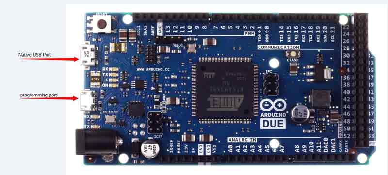
Both USB ports can be used to download programs to the Due. Due to the influence of the chip erasing method, it is recommended to use the programming port:
Programming Port: To use this port to download, you need to select "Arduino Due (Programming Port)" as your board in arduinoIDE. Connect the programming port (the one near the DC socket) to your computer. The programming port uses 16U2 as a USB-to-serial connection to the first UART (RX0 and TX0) of the SAM3X. There are two pins on the 16U2 that connect to the reset and erase pins of the SAM3X. At 1200 baud rate, opening and closing the serial port will trigger the hard erase program of SAM3X, trigger the erase and reset pin of SAM3X through the serial port before communication. It is recommended to use this port to upload programs to Arduino. Compared with using the native USB port to softly erase the chip, using the programming port to hard erase is more stable and reliable. Even if the main chip is broken, the port will still work.
Native port: To use this port to download, you need to select “Arduino Due (Native USB Port)” as your board in arduinoIDE. Connect the native USB port (the one near the reset button) to your computer. Under 1200 Portland, opening and closing the serial port will trigger the soft erase program of SAM3X: the flash space is erased, and the program reverses to the bootloader area. If the main chip is damaged, the soft erase program will not work, this is because the program is entirely on the SAM3X. Switching native USB port baudrate will not reset SAM3X.
Unlike other Arduino controllers that use avrdude to upload the program, the Due upload program relies on bossac.
The ATmega16U2 firmware source code can be found in the arduino library. You can use an external programmer to program the firmware (override the DFU bootloader) through the ISP interface. For more information, please refer to the relevant documentation.
USB overcurrent protection
There is a resettable fuse on the Arduino Due, which can be automatically disconnected in case of short circuit or overcurrent, thus protecting your computer USB. Most computers have internal overcurrent protection, and this fuse provides an extra layer of protection. When the current is greater than 500MA, the fuse will automatically disconnect until there is no overload or short circuit.
Form Factor and Shield Compatibility
It looks the same as 2560. The expansion board is compatible and considers the level.