


- sales/support
Google Chat:---
- sales
+86-0755-88291180
- sales01
sales@spotpear.com
- sales02
dragon_manager@163.com
- support
tech-support@spotpear.com
- CEO-Complaints
zhoujie@spotpear.com
- Only Tech-Support
WhatsApp:13246739196
- Purchase/Shipping/Refund
WhatsApp:13424403025
Raspberry Pi SX1262 868M LoRa HAT User Guide
Introduction
- This product is a Raspberry Pi expansion board based on SX1268/SX1262 chip, a wireless serial port module with LoRa modulation function.
- With multi-level relay to achieve ultra-long-distance communication, low power consumption wake-up communication, encrypted transmission, etc.
- This product uses a private protocol and does not support LoRaWAN.
Features
- Support global license-free ISM 433/470/868/915MHz frequency band.
- Supports wake-on-air, that is, ultra-low power consumption, suitable for battery-powered applications.
- Support point-to-point transmission, broadcast transmission, channel monitoring, and multi-level relaying for ultra-long-distance communication.
- Support RSSI signal indicator for evaluating signal quality and improving communication network.
- Support the LBT function, and monitor the channel environmental noise before sending, which can greatly improve the communication success rate of the module in harsh environments.
- LoRa spread spectrum technology, up to 84 channels/81 channels (SX1268/SX1262).
- Support waking on radio, online configuration, carrier sense, automatic relay, communication key, low power sleep.
- In an ideal environment, the communication distance can reach 5KM.
Specification
| Consumption | Transmit Current | 100mA (Transient current) |
| Receive Current | 11mA | |
| Sleep Current | 2uA (LoRa module deep sleep) | |
| MAX Transmit Power | 22.0dBm (10, 13, 17, 22dBm Selectable) | |
| Transmit Length | 240 Bytes (32, 64, 128, 240 Bytes Selectable) | |
| Buffer | 1000 Bytes | |
| Working Bands | 410.125~493.125MHz or 850.125~930.125MHz | |
| Receive Sensitivity | -147dBm@0.3Kbps (On air) | |
| Air Speed | 0.3K~62.5Kbps (software selectable) | |
| Interface | UART | |
| Range | 5KM (Sunny day; open area; Antenna: AUX 5dBi, Height 2.5m; Air Speed: 2.4kbps) | |
| Working Voltage | 5V | |
| Logic Voltage | 3.3V | |
| Working Temperature | -40 ~ 85°C | |
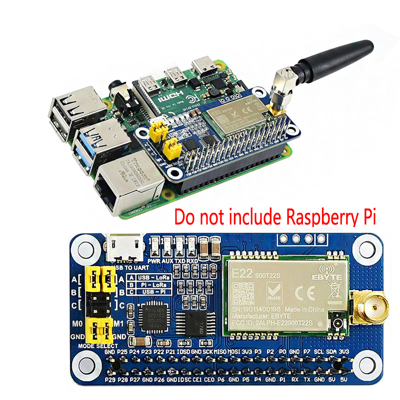
Hardware description
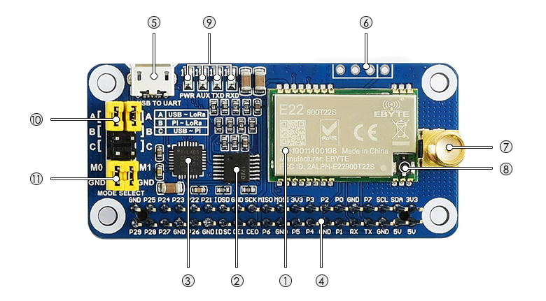
- SX1268/SX1262 LoRa module
- 74HC125V: voltage level translator
- CP2102: USB TO UART converter
- Raspberry Pi GPIO connector: for connecting with Raspberry Pi
- USB TO UART port
- UART header: for connecting MCU
- SMA antenna connector
- IPEX antenna connector
- Indicators:
- RXD/TXD: UART RX/TX indicator
- AUX: auxiliary indicator
- PWR: power indicator
- UART selection jumpers
- A: control the LoRa module through USB TO UART
- B: control the LoRa module through Raspberry Pi
- C: access Raspberry Pi through USB TO UART
- LoRa mode selection jumpers
- short M0, short M1: transmission mode
- short M0, open M1: configuration mode
- open M0, short M1: WOR mode
- open M0, open M1: deep sleep mode
【Note】
1. Combine M1 and M0 with high and low levels to determine the working mode. M1 and M0 are high when they are not connected to the jumper cap. After switching the working mode, if the module is idle, it will enter the new working mode. Otherwise, the current transmission will be processed and enter the new working mode after receiving.
2. Mode 0: Transmission mode, Module transmits data when users send data to the UART interface. Wireless receiving is enabled to receive data and send it to the UART interface when idle.
3. Mode 1: When it is defined to Transmit, the user needs to add wakeup codes before transmitting, receiving is the same as Mode 0.
4. Mode 2: Wireless transmit and wireless receive are disabled, users can configure configuration according to #Registers Configuration
5. Mode 3: Wireless transmit and wireless receive are disabled, and the module enters deep sleep mode. The module will configure when switching to other modes.
LoRa & LoRaWAN
What's LoRa
Semtech's LoRa is IoT wireless platform with long-distance and low-power, generally referring to radio frequency chips in LoRa. The main features are as follows.
- The spread spectrum modulation technology used by LoRa (abbreviation of long-range) is derived from chirp spread spectrum (CSS) technology, which is one of the long-distance wireless transmission technology and LPWAN communication technology. At present, LoRa in the ISM frequency band mainly includes 433, 868, 915 MHz, etc.
- Integrating digital spread spectrum, digital signal processing, and forward error correction codes, the performance of long-distance communication in LoRa has been improved a lot. Moreover, the link budget in LoRa, the main factor that determines distance under a given environment, is better than any other standardized communication technology.
- LoRa RF chips mainly include SX127X series, SX126X series, and SX130X series, of which SX127X, SX126X series are used for LoRa nodes, and SX130X is used for LoRa gateways. For details, please refer to Semtech's product list.
What's LoRaWAN
LoRaWAN is a low-power, wide-area networking (LPWAN) protocol based on LoRa Technology. It is designed to wirelessly connect battery-operated 'things' to the Internet in regional, national, or global networks, and targets key Internet of Things (IoT) requirements such as bi-directional communication, end-to-end security, mobility, and localization services. The node wirelessly connected to the Internet has network access authentication, which is equivalent to establishing an encrypted communication channel between the node and the server. For details of network access, refer to source code. The LoRaWAN protocol level is shown in the figure below.
- Class A/B/C node devices in the MAC cover all the applications for the Internet of Things. The difference between them is that the time slots for nodes to send and receive are different.
- The band parameters in Modulation, such as EU868 and AS430, are differnt in differnt contries. The regional parameters refer to link.

- The LoRaWAN coverage in the city or other areas requires a node (LoRa node radio frequency chip), gateway (or base station, LoRa gateway radio frequency chip), server, and cloud. As shown in the following figure:
- First, DEVICE (node device) sends network access data package to GATEWAY and then to the server. After the authentication is passed, it can send and receive application data with the server normally.
- GATEWAY (gateway) can communicate with the server through a wired network, 3/4/5G wireless network.
- The main operators on the server side include TTN, etc. If you want to build cloud services by yourself, please refer to lorawan-stack,chirpstack

Application
LoRa devices and networks such as LoRaWAN enable smart IoT applications to help the planet's present challenges such as energy management, natural resource reduction, pollution control, infrastructure efficiency, disaster prevention, and so on. Semtech's LoRa devices have been successfully applied in many aspects such as smart cities, homes and buildings, communities, metrology, supply chain and logistics, agriculture, and so on. LoRa networks reach hundreds of millions of devices in more than 100 countries for a smarter planet.
Working with PC
SSCOM connection test
- 1. Prepare two SX126x LoRa HAT modules (here called Lora HAT), two Micro USB cables, assemble SMA antennas, place the jumper cap on A, and connect M0 and M1 to GND.
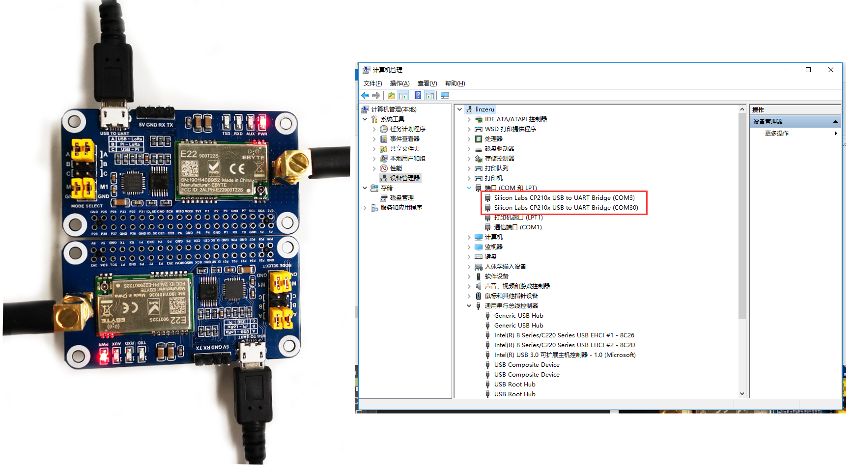
- 2. Install the CP2102 driver on the WINDOWS PC, and connect the two Lora HATs to the PC using Micro USB.
- 3. Open the PC device manager, find the two COM ports corresponding to the CP2102, use the SSCOM serial port software to connect the two Lora modules respectively, and set the baud rate to 9600.
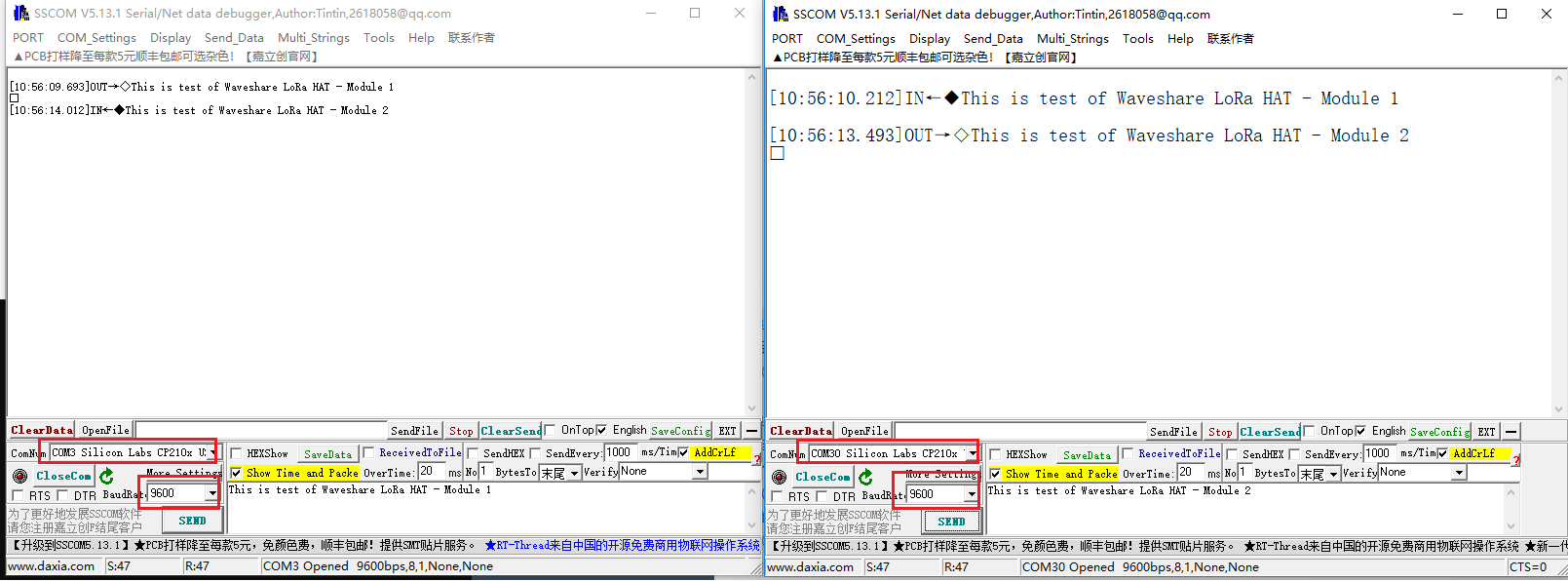
- 4. Input data in the input field of one SSCOM serial port software, click the send button, and you can see the data received by the LoRa module in the display field of the other SSCOM serial port software.
Terminal
This test uses a Windows PC to connect to the LoRa HAT, and the jump settings will not change according to the factory location.
1. Install python3 on Windows, then enter cmd in the startup bar to search and open the Windows terminal.
2. Enter the path of python3 into the terminal, the default address is generally as shown in the picture below, pay attention to check your python3 path, and install pyserial.
path=%path%;C:\Users\zhongshaohua\AppData\Local\Programs\Python\Python37\Scripts\
path=%path%;C:\Users\zhongshaohua\AppData\Local\Programs\Python\Python37\
pip3 install pyserial
3. Use the host computer software to set up LoRa HAT, unplug the M1 jumper when setting, connect to the M1 jumper, and close the serial port of the upper computer after the setting is completed. Set the parameters as follows:
4. Unzip the sample demo to the desktop, open the main.py file to modify the COM port, and then run the demo.
Working with Raspberry Pi
In this chapter, we will demonstrate two examples. Demo 1: the test of two LoRa HATs connect to two Raspberry Pis for receiving and sending. Demo 2: The test of using 3 LoRa HATs for relay communication receiving and sending.
Hardware Connection, Install Function, Enable Raspberry Pi Serial Port, Download Demo
1. Hardware connection: After powering on Raspberry Pi, connect LoRa HAT as shown below:

Enter the following commands one by one to install the Python library, the first command enables the Raspberry Pi serial port.
#The system higher than version 2021.10.30 no longer needs to install the serial library.
#sudo apt install python-serial
sudo raspi-config
cd Documents
wget https://files.waveshare.com/upload/1/18/SX126X_LoRa_HAT_CODE.zip
unzip SX126X_LoRa_HAT_CODE.zip
2. Enable serial port.
- Open the Terminal of Raspberry Pi.
- Run command sudo raspi-config to open Configure interface.
- Choose Interfacing Options -> Serial -> No -> Yes.

Demo 1
After executing the following command, the node will automatically print to the terminal when it receives the data sent by other nodes. When the node needs to send data to other nodes, press the keyboard i, and then enter the input according to the prompt, as shown in the figure below:
cd ~/Documents/SX126X_LoRa_HAT_Code/raspberrypi/python/
sudo python3 main.py


Demo 2
Relay communication is a method for ultra-long-distance communication. Setting up the LoRa module to relay mode, and its address register would be only for forwarding pairing, no more active transceiver function, and no low power consumption.
【Note】 To test the Relay example, you require at least three LoRa HATs.
- Assume the three LoRa modules as LoRa module A, LoRa module B, and LoRa module C.
- Directly connected LoRa module A to the Raspberry Pi, set up LoR module B and LoRa module C by Windows upper-computer.


- After LoRa module A is connected to the Raspberry Pi, open the main.py file, change line 66, change realy=False to realy=True, and execute the following command, LoRa module C will print the data from the serial port after receiving the data, and relay the LoRa module B will not print any data from the serial port, enter the following command:
cd ~/Documents/SX126X_LoRa_HAT_Code/RaspberryPi/python/
# node = sx126x.sx126x(serial_num = "/dev/ttyS0",freq=868,addr=0,power=22,rssi=True,air_speed=2400,relay=True)
sudo python3 main.py
Working with STM32
This demo uses STM32F103CBT6 based on the HAT function.
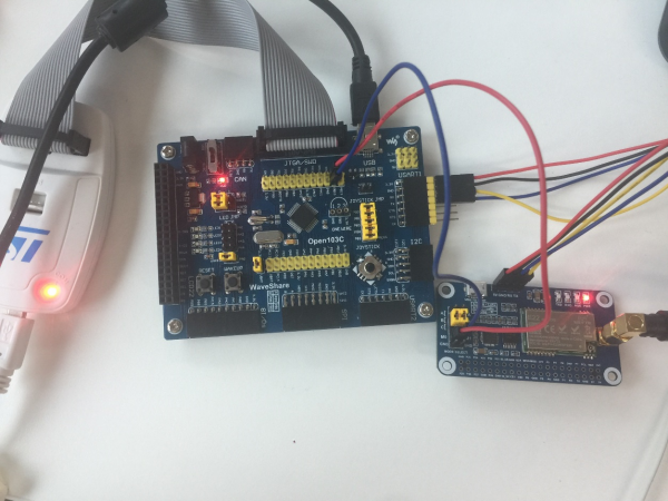
Hardware Connection
Connect the jumper cap to B, and remove the M0, and M1 jumper caps instead of using the GPIO of STM32F103C.
| SX1268 LoRa HAT | STM32 |
|---|---|
| 5V | 5V |
| GND | GND |
| RXD | PA10 |
| TXD | PA9 |
| M1 | PB15 |
| M0 | PB14 |
2. Example
- The settings of the LoRa module connected to the computer USB are the same as in the above three demos.
- Open the Keil project document and use different definitions in communication methods in lines 75 to 77 of the main.c file.
#define TRASNSPARENT
//#define RELAY
//#define WOR- Select the communication method above and press F7 to compile, press F8 to download to STM32.
Demo Brief Analysis
In this section, we briefly describe the working process and Python program of this product.
- After powering on, and setting up /dev/ttyS0 serial port and 9600 baud rate, the M0 (BCM22) pin of the module is in low level, M1 (BCM27) pin is in high level, the module enters the configuration mode:
 def __init__(self,serial_num,freq,addr,power,rssi,air_speed=2400,\
                 net_id=0,buffer_size = 240,crypt=0,\
                 relay=False,lbt=False,wor=False):
        self.rssi = rssi
        self.addr = addr
        self.freq = freq
        self.serial_n = serial_num
        self.power = power
        # Initial the GPIO for M0 and M1 Pin
        GPIO.setmode(GPIO.BCM)
        GPIO.setwarnings(False)
        GPIO.setup(self.M0,GPIO.OUT)
        GPIO.setup(self.M1,GPIO.OUT)
        GPIO.output(self.M0,GPIO.LOW)
        GPIO.output(self.M1,GPIO.HIGH)

        # The hardware UART of Pi3B+,Pi4B is /dev/ttyS0
        self.ser = serial.Serial(serial_num,9600)
        self.ser.flushInput()
        self.set(freq,addr,power,rssi,air_speed,net_id,buffer_size,crypt,relay,lbt,wor)
- Lines 11 to 77 in the following code set the LoRa module's low address, high address, network ID, frequency, airspeed size, cache size, power size, RSSI input enable, encryption key and whether it is enabled the relay mode parameters, click to check register descriptionand LoRa Configuration. Lines 79 to 113 are the serial port sending configuration commands to the LoRa module. If the configuration is correct, pull down the M1 pin to enter the transceiver mode.
 def set(self,freq,addr,power,rssi,air_speed=2400,\
            net_id=0,buffer_size = 240,crypt=0,\
            relay=False,lbt=False,wor=False):
        self.send_to = addr
        self.addr = addr
        # We should pull up the M1 pin when sets the module
        GPIO.output(self.M0,GPIO.LOW)
        GPIO.output(self.M1,GPIO.HIGH)
        time.sleep(0.1)

        low_addr = addr & 0xff
        high_addr = addr >> 8 & 0xff
        net_id_temp = net_id & 0xff
        if freq > 850:
            freq_temp = freq - 850
            self.start_freq = 850
            self.offset_freq = freq_temp
        elif freq >410:
            freq_temp = freq - 410
            self.start_freq  = 410
            self.offset_freq = freq_temp

        air_speed_temp = self.lora_air_speed_dic.get(air_speed,None)
        # if air_speed_temp != None

        buffer_size_temp = self.lora_buffer_size_dic.get(buffer_size,None)
        # if air_speed_temp != None:

        power_temp = self.lora_power_dic.get(power,None)
        #if power_temp != None:

        if rssi:
            # enable print rssi value
            rssi_temp = 0x80
        else:
            # disable print rssi value
            rssi_temp = 0x00

        # get crypt
        l_crypt = crypt & 0xff
        h_crypt = crypt >> 8 & 0xff

        if relay==False:
            self.cfg_reg[3] = high_addr
            self.cfg_reg[4] = low_addr
            self.cfg_reg[5] = net_id_temp
            self.cfg_reg[6] = self.SX126X_UART_BAUDRATE_9600 + air_speed_temp
            #
            # it will enable to read noise rssi value when add 0x20 as follow
            #
            self.cfg_reg[7] = buffer_size_temp + power_temp + 0x20
            self.cfg_reg[8] = freq_temp
            #
            # it will output a packet rssi value following received message
            # when enable eighth bit with 06H register(rssi_temp = 0x80)
            #
            self.cfg_reg[9] = 0x43 + rssi_temp
            self.cfg_reg[10] = h_crypt
            self.cfg_reg[11] = l_crypt
        else:
            self.cfg_reg[3] = 0x01
            self.cfg_reg[4] = 0x02
            self.cfg_reg[5] = 0x03
            self.cfg_reg[6] = self.SX126X_UART_BAUDRATE_9600 + air_speed_temp
            #
            # it will enable to read noise rssi value when adding 0x20 as follows
            #
            self.cfg_reg[7] = buffer_size_temp + power_temp + 0x20
            self.cfg_reg[8] = freq_temp
            #
            # it will output a packet rssi value following the received message
            # when enable eighth bit with 06H register(rssi_temp = 0x80)
            #
            self.cfg_reg[9] = 0x03 + rssi_temp
            self.cfg_reg[10] = h_crypt
            self.cfg_reg[11] = l_crypt
        self.ser.flushInput()

        for i in range(2):
            self.ser.write(bytes(self.cfg_reg))
            r_buff = 0
            time.sleep(0.2)
            if self.ser.inWaiting() > 0:
                time.sleep(0.1)
                r_buff = self.ser.read(self.ser.inWaiting())
                if r_buff[0] == 0xC1:
                    pass
                    # print("parameters setting is :",end='')
                    # for i in self.cfg_reg:
                        # print(hex(i),end=' ')

                    # print('\r\n')
                    # print("parameters return is  :",end='')
                    # for i in r_buff:
                        # print(hex(i),end=' ')
                    # print('\r\n')
                else:
                    pass
                    #print("parameters setting fail :",r_buff)
                break
            else:
                print("setting fail,setting again")
                self.ser.flushInput()
                time.sleep(0.2)
                print('\x1b[1A',end='\r')
                if i == 1:
                    print("setting fail,Press Esc to Exit and run again")
                    # time.sleep(2)
                    # print('\x1b[1A',end='\r')

        GPIO.output(self.M0,GPIO.LOW)
        GPIO.output(self.M1,GPIO.LOW)
        time.sleep(0.1)
*The serial port sends application data to the LoRa module and sends other LoRa nodes wirelessly.
 # The data format like as follows
 # "node address,frequency,payload"
 # "20,868, Hello World"
    def send(self,data):
        GPIO.output(self.M1,GPIO.LOW)
        GPIO.output(self.M0,GPIO.LOW)
        time.sleep(0.1)

        self.ser.write(data)
        # if self.rssi == True:
            # self.get_channel_rssi()
        time.sleep(0.1)
- Data received by the receiver send to the controller from the serial output and pay attention to the third line of code. If the amount of received data is too large, please increase the delay accordingly and wait for all the data to be received before reading. Lines 10 to 15 are based on whether RSSI Enable to print RSSI value.
 def receive(self):
        if self.ser.inWaiting() > 0:
            time.sleep(0.5)
            r_buff = self.ser.read(self.ser.inWaiting())

            print("receive message from node address with frequence\033[1;32m %d,%d.125MHz\033[0m"%((r_buff[0] <<8)+r_buff[1],r_buff[2]+self.start_freq),end='\r\n',flush = True)
            print("message is "+str(r_buff[3:-1]),end='\r\n')

            # print the rssi
            if self.rssi:
                # print('\x1b[3A',end='\r')
                print("the packet rssi value: -{0}dBm".format(256-r_buff[-1:][0]))
                self.get_channel_rssi()
            else:
                pass
                #print('\x1b[2A',end='\r')
- In the main.py file, after the program runs, wait for the user to press the keyboard to perform the corresponding operation, enter Esc to exit the loop, enter i to enter the application information to be sent, and enter s to broadcast the CPU temperature every 10 seconds:
 try:
    time.sleep(1)
    print("Press \033[1;32mEsc\033[0m to exit")
    print("Press \033[1;32mi\033[0m   to send")
    print("Press \033[1;32ms\033[0m   to send cpu temperature every 10 seconds")

    # it will send rpi cpu temperature every 10 seconds
    seconds = 10

    while True:
        if select.select([sys.stdin], [], [], 0) == ([sys.stdin], [], []):
            c = sys.stdin.read(1)

            # dectect key Esc
            if c == '\x1b': break
            # dectect key i
            if c == '\x69':
                send_deal()
            # dectect key s
            if c == '\x73':
                print("Press \033[1;32mc\033[0m   to exit the send task")
                timer_task = Timer(seconds,send_cpu_continue)
                timer_task.start()

                while True:
                    if sys.stdin.read(1) == '\x63':
                        timer_task.cancel()
                        print('\x1b[1A',end='\r')
                        print(" "*100)
                        print('\x1b[1A',end='\r')
                        break

            sys.stdout.flush()

        node.receive()

        # timer,send messages automatically
 except:
    termios.tcsetattr(sys.stdin, termios.TCSADRAIN, old_settings)
Resources
Documents
Demo codes
Related Links
Softwares
FAQ
Question:Why is the transmission distance not ideal?
- The ground absorbs and reflects radio waves, and the testing effect is poor near the ground; when there is a linear communication barrier, the communication distance will be attenuated accordingly.
- There are metal objects near the antenna, or placed in a metal shell, the signal attenuation will be very serious; seawater has a strong ability to absorb radio waves, so the seaside test effect is poor.
- Temperature, humidity, and co-channel interference will lead to increased communication packet loss rate; power supply low voltage at room temperature is lower than the recommended value, the lower the voltage the smaller the power generation.
- Wrong setting of power register, too high setting of air rate (the higher the air rate, the closer the distance).
Question:Why can't I read the parameters on the computer?
Set up the upper jumper cap to B; remove the lower jumper cap M2 and you can read the parameters:

Question:Do SX1262 and SX1268 support LoRaWAN network protocol?
No. If you need to support the LoRaWAN network protocol, buy this Pico-LoRa-SX1262-868M, which can be matched with LoRaWAN gateway SX1302 LoRaWAN Gateway HAT
Additional instructions:
In the OSI model of a computer network, LoRa is located in the bottom physical layer, which generally refers to the radio frequency chip using LoRa technology;
LoRaWAN is a set of protocol standards based on the MAC layer based on the LoRa transmission technology. With this standard, LoRaWAN becomes a network technology.
If it only supports Lora but does not support Lorwan, point-to-point communication is supported. However, network connections with higher-standard do not support. If you want to establish LoRa network with larger scale, it is recommended to use LoWAN protocol.
Question:Why does it work in windows, but not in Raspberry Pi with the demo?
It may be the serial port issue, the default serial port used by the program is ttyS0, Raspberry Pi serial port may not be, you can use the following command to confirm (serial0 corresponds to the selected serial port):
ls -l /dev/serial*

470M and 433M module demos are the same, and the default use of 433M program; 915M and 868M are used 868M program, the default program is 433M, change the comment:
- It may be a system issue, please check it and use the stable Raspberry Pi Buster system
Question:Can it communicate with other LoRa modules?
- No, the RF parameters of the LoRa module are not the same, also, there are differences among internal design, communication protocol, data encoder, and so on.
- For example, Two or more SX1262 433M LoRa HATs are needed to realize the communication, used in pairs, can not communicate with other series of Lora
- Therefore, please choose the same LoRa module to ensure the consistency of hardware and protocol.
Question:What is the difference between stream mode and packet mode?
- Stream mode (non-acknowledgment mode):
In stream mode, LoRa devices do not wait for acknowledgment from the receiver after sending data. This mode is suitable for applications that require high real-time performance or have low requirements for data integrity.
- Packet mode (acknowledgment mode):
In packet mode, LoRa devices wait for an acknowledgment (ACK) from the receiver after sending data. This mode is suitable for applications that need to ensure data integrity and reliability.
Support
[Tutorial Navigation]
- Introduction
- Working with PC
- Working with Raspberry Pi
- Working with STM32
- Resources
- FAQ
- Question:Why is the transmission distance not ideal?
- Question:Why can't I read the parameters on the computer?
- Question:Do SX1262 and SX1268 support LoRaWAN network protocol?
- Question:Why does it work in windows, but not in Raspberry Pi with the demo?
- Question:Can it communicate with other LoRa modules?
- Question:What is the difference between stream mode and packet mode?
- Support