- sales/support
Google Chat:---
- sales
+86-0755-88291180
- sales01
sales@spotpear.com
- sales02
dragon_manager@163.com
- support
tech-support@spotpear.com
- CEO-Complaints
zhoujie@spotpear.com
- Only Tech-Support
WhatsApp:13246739196
- Purchase/Shipping/Refund
WhatsApp:13424403025
- HOME
- >
- ARTICLES
- >
- Common Moudle
- >
- ESP
ESP32-P4-WIFI6-POE-ETH User Guide
Features
- Processor
- Equipped with a RISC-V 32-bit dual-core processor (HP system), featuring DSP and ISA extensions, a Floating-Point Unit (FPU), with a main frequency of up to 360 MHz.
- Equipped with a RISC-V 32-bit single-core processor (LP system), with a main frequency of up to 40 MHz.
- Equipped with an ESP32-C6 WIFI/BT co-processor, expanding WIFI 6/Bluetooth 5 and other functions through SDIO
- Memory
- 128 KB of high-performance (HP) system read-only memory (ROM).
- 16 KB of low-power (LP) system read-only memory (ROM).
- 768 KB of high-performance (HP) L2 memory (L2MEM).
- 32 KB of low-power (LP) SRAM.
- 8 KB of system tightly coupled memory (TCM).
- 32 MB PSRAM stacked in the package, and 32MB Nor Flash integrated on the module
- Peripheral Interfaces
- 2×20 headers bring out 28 remaining programmable GPIOs, supporting a wide range of peripherals
- Onboard Type-A USB 2.0 OTG port, 100Mbps Ethernet port (supports PoE), SDIO3.0 TF card slot, Type-C UART flashing port, convenient for different scenarios
- Onboard speaker interface and microphone, enabling ideal audio functionality using the Codec chip and amplifier chip
- Onboard MIPI-CSI high-definition camera interface, supporting Full HD 1080P image capture and encoding, integrated Image Signal Processor (ISP), H.264 video encoder, supports H.264 & JPEG video encoding (1080P @30fps), facilitating applications in computer vision, machine vision, and other fields
- Onboard MIPI-DSI high-definition display interface, integrated Pixel Processing Accelerator (PPA), 2D graphics acceleration controller (2D DMA), supports JPEG image decoding (1080P @30fps), providing strong support for high-definition display and smooth HMI experiences, suitable for applications such as smart home control panels, industrial control panels, and vending machines
- Reserved PoE module interface, making the board's power supply more flexible. With only a single Ethernet cable connected to a PoE device, the ESP32-P4-WIFI6-POE-ETH series can achieve both networking and power delivery
Hardware Description
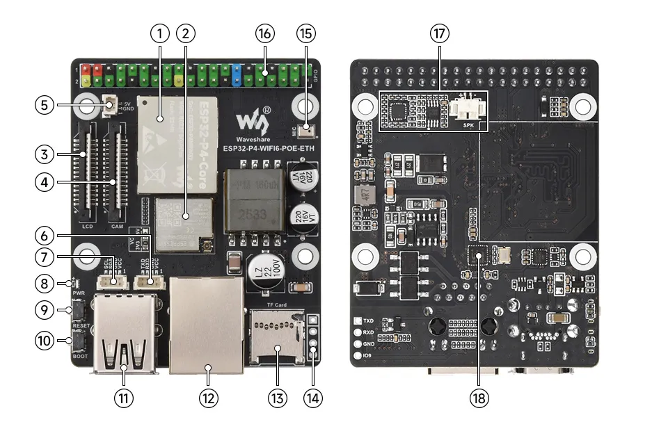
- ESP32-P4-Core Integrates ESP32-P4NRW32 and 32MB NOR Flash
- ESP32-C6-MINI-1U-H8 Module SDIO interface protocol, compatible with the development board for Wi-Fi 6, Bluetooth 5 (LE); external antenna uses IPEX 3rd-generation connector.
- Display Interface MIPI-DSI (2-lane), compatible with
5/7/8/10.1inch DSI screens - Camera Interface MIPI-CSI (2-lane), compatible with cameras such as
OV5647 - 5V Power Supply Header
- UART Header SH1.0 4PIN For program flashing and debugging
- I2C Header SH1.0 4PIN For connecting external I2C devices
- Power indicator
- RST Button Reset button
- BOOT Button Press it when powering on or resetting to enter download mode
- Type-A and Type-C physical stacked design Type-A as USB OTG 2.0 High Speed port; Type-C as the UART port, for power supply, program flashing and debugging
- 100Mbps RJ45 Ethernet Port Supports PoE function
- TF Card Slot SDIO 3.0 interface protocol
- ESP32-C6 UART Terminal
- SMD Microphone
- 40Pin Header
- Audio Codec Chip, Amplifier Chip, and MX1.25 Speaker Header MX1.25 2P connector, supports 8Ω 2W speaker
- IP101 Ethernet port chip
Pinout Definition
| Version | Header Appearance | Description |
|---|---|---|
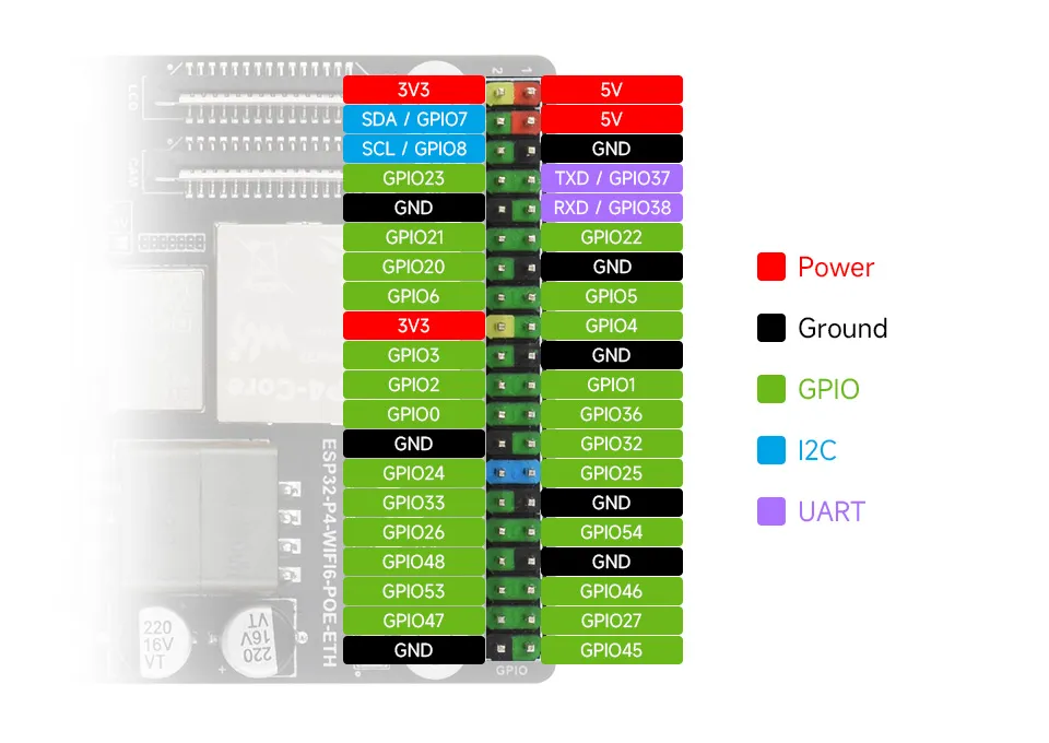
| Newer Version | Colored pin headers | Current version shown on product page; documentation uses this version by default |
| Earlier Version | Black pin headers | Retained to distinguish appearance differences in early batches |
Dimensions
Working with ESP-IDF
This chapter covers:
- ESP-IDF Getting Started
- Setting Up the ESP-IDF Development Environment
- ESP32-P4 Platform Example Repository
ESP-IDF Getting Started
New to ESP32 ESP-IDF development and looking to get started quickly? We have prepared a general Getting Started Tutorial for you.
- Section 1: Environment Setup
- Section 2: Running Examples
- Section 3: Creating a Project
- Section 4: Using Components
- Section 5: Debugging
- Section 6: FreeRTOS
- Section 7: Peripherals
- Section 8: Wi-Fi Programming
- Section 9: BLE Programming
Please Note: This tutorial uses the ESP32-S3-Zero as a teaching example, and all hardware code is based on its pinout. Before you start, it is recommended that you check the pinout of your development board to ensure the pin configuration is correct.
Setting Up the ESP-IDF Development Environment
The ESP32-P4 Platform examples target ESP-IDF release/v5.4 and later. ESP-IDF v5.5.4 is recommended. For individual advanced UI examples, check the example directory README for specific version requirements.
The following guide uses Windows as an example, demonstrating development using VS Code + the ESP-IDF extension. macOS and Linux users should refer to the official documentation.
The screenshots in this section use ESP-IDF V5.5.2 as an example. When installing, please select the ESP-IDF version that matches your board's example.
Install the ESP-IDF Development Environment
Download the installation manager from the ESP-IDF Installation Manager page. This is Espressif's latest cross-platform installer. The following steps demonstrate how to use its offline installation feature.
Click the Offline Installer tab on the page, then select Windows as the operating system and the ESP-IDF version you need (the version shown in the screenshot is for reference only — choose the version that fits your actual needs).
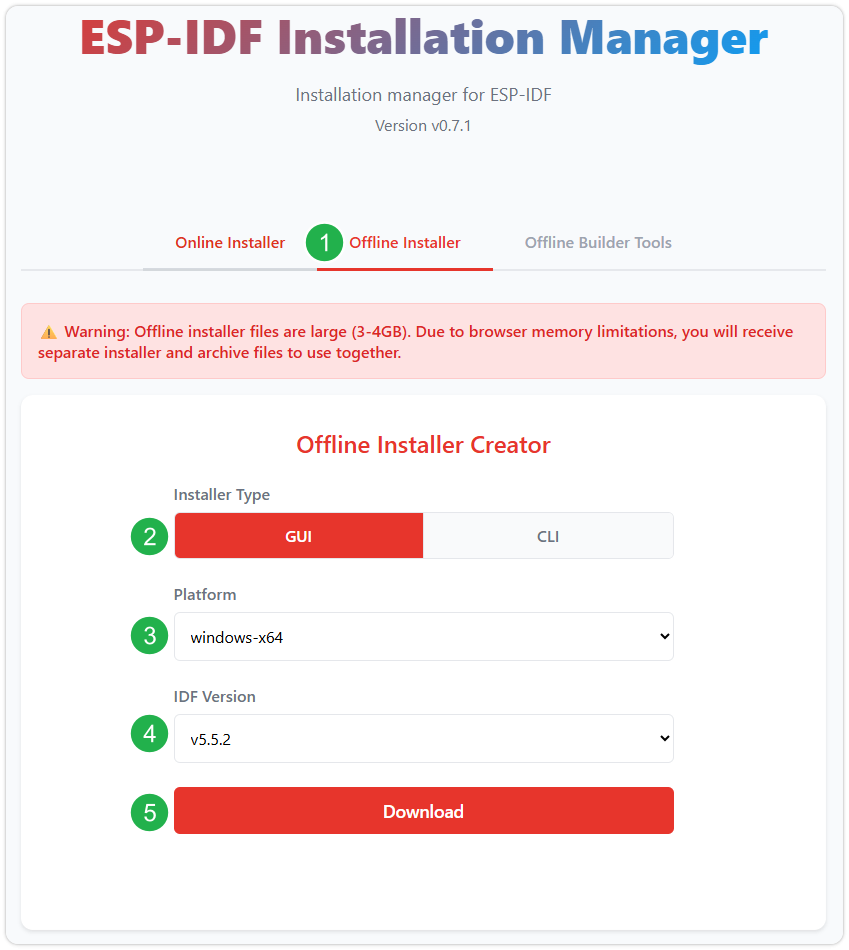
After confirming your selection, click the download button. The browser will automatically download two files: the ESP-IDF Offline Package (.zst) and the ESP-IDF Installer (.exe).
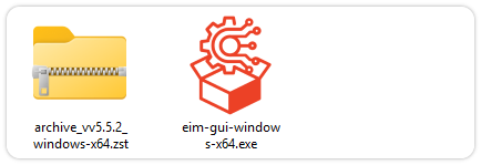
Please wait for both files to finish downloading.
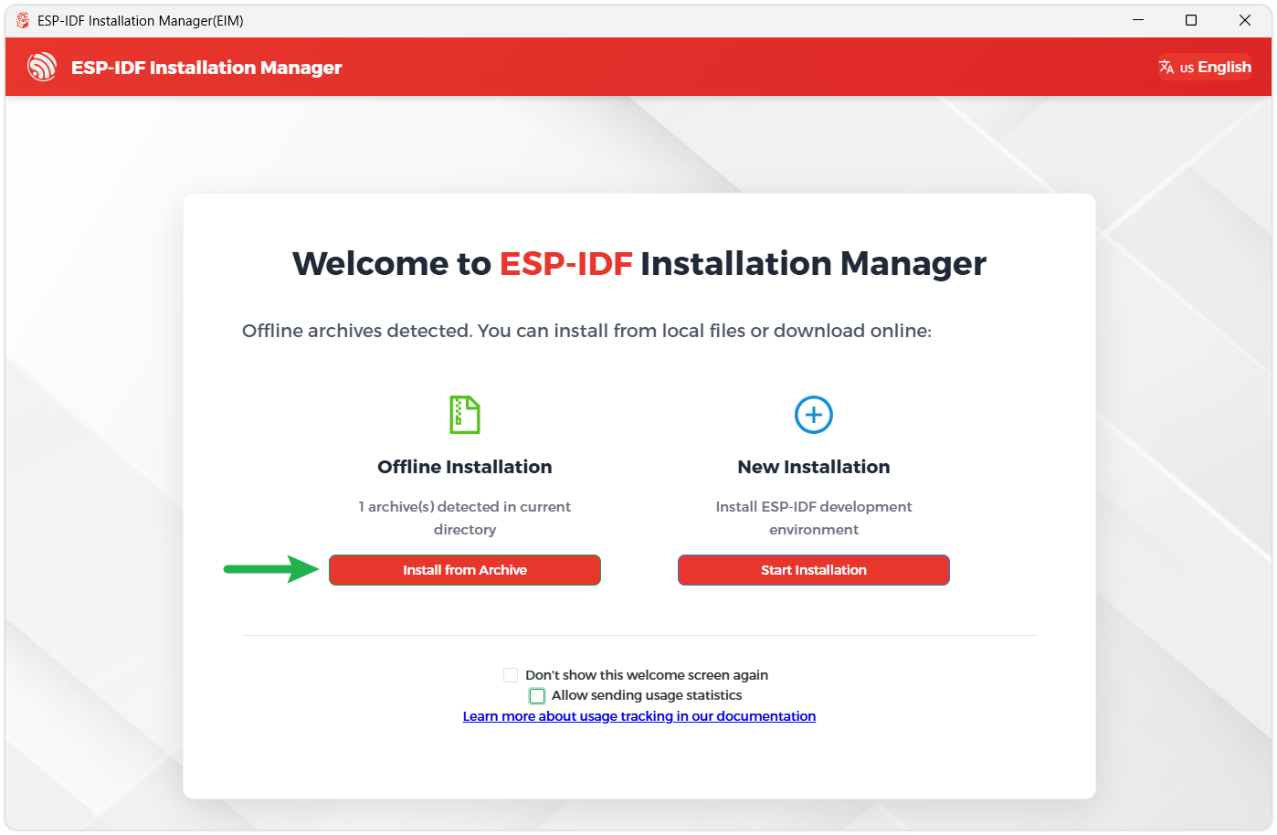
Once the download is complete, double-click to run the ESP-IDF Installer (eim-gui-windows-x64.exe).
The installer will automatically detect if the offline package exists in the same directory. Click Install from archive.
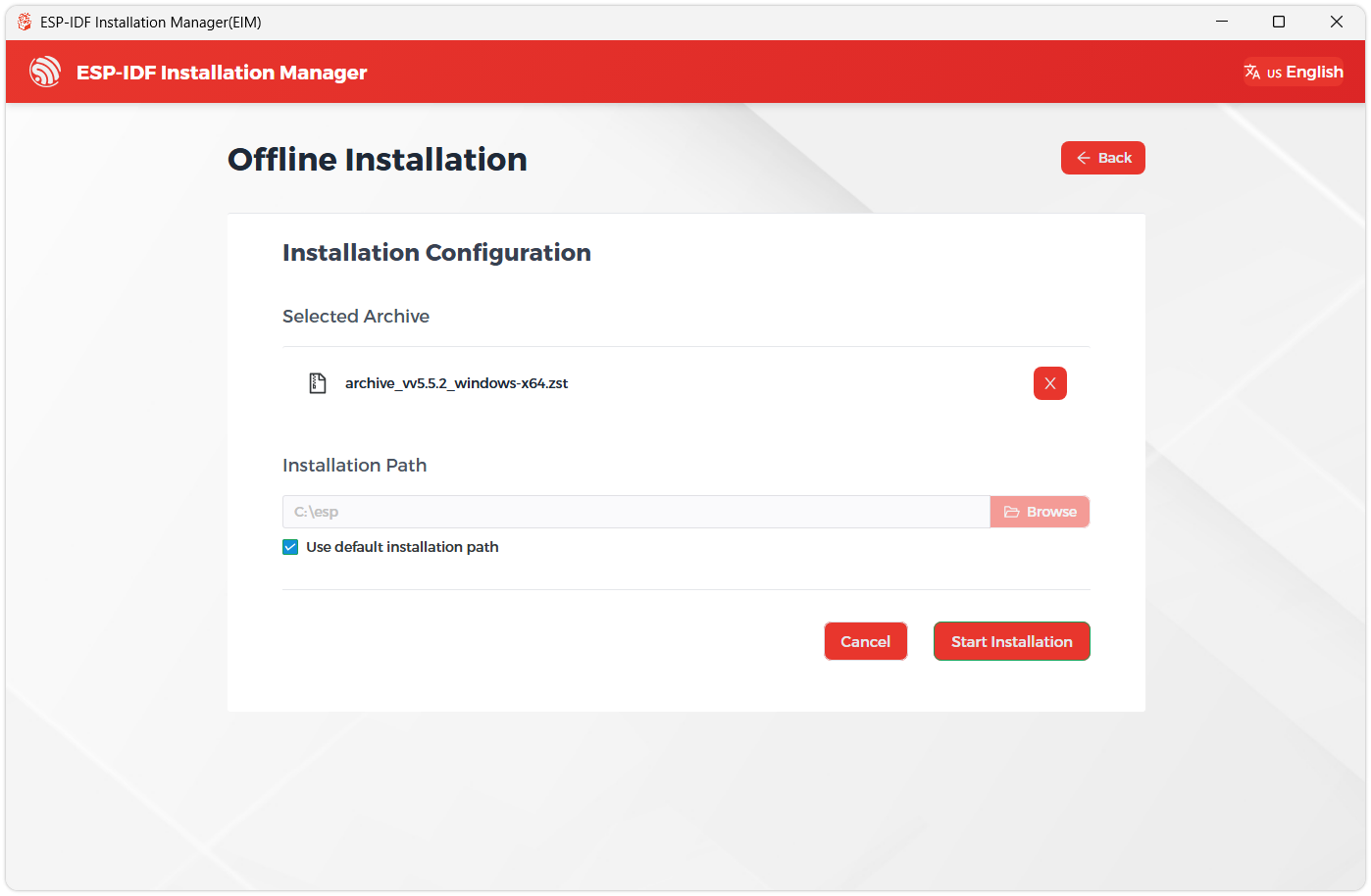
Next, select the installation path. We recommend using the default path. If you need to customize it, ensure the path does not contain Chinese characters or spaces. Click Start installation to proceed.
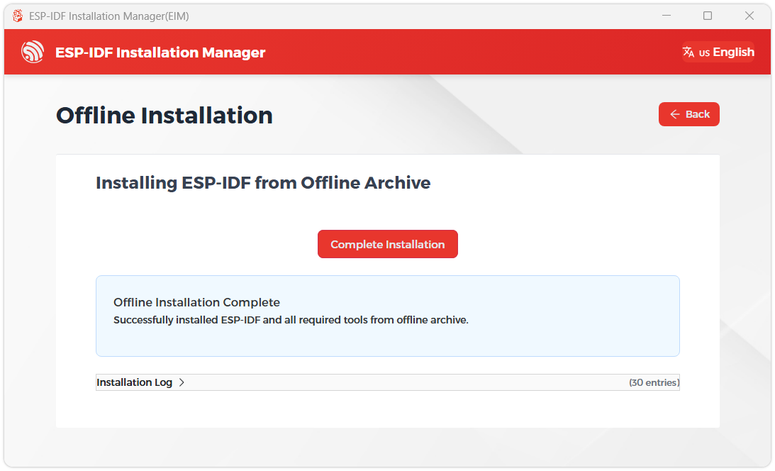
When you see the following screen, the ESP-IDF installation is successful.
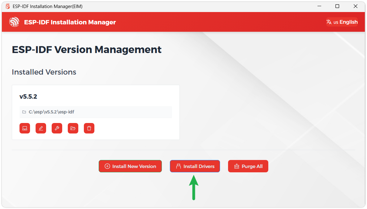
We recommend installing the drivers as well. Click Finish installation, then select Install driver.
Install Visual Studio Code and the ESP-IDF Extension
Download and install Visual Studio Code.
During installation, it is recommended to check Add "Open with Code" action to Windows Explorer file context menu to facilitate opening project folders quickly.
In VS Code, click the Extensions icon
 in the Activity Bar on the side (or use the shortcut Ctrl + Shift + X) to open the Extensions view.
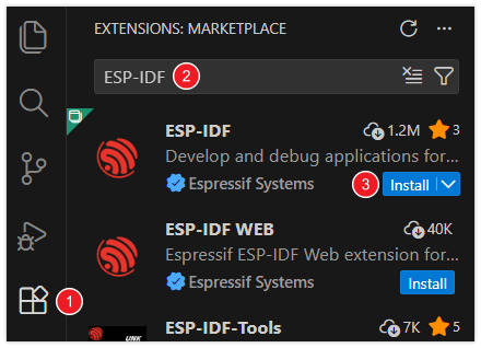
Enter ESP-IDF in the search box, locate the ESP-IDF extension, and click Install.
For ESP-IDF extension versions ≥ 2.0, the extension will automatically detect and recognize the ESP-IDF environment installed in the previous steps, requiring no manual configuration.
Firmware Flashing and Erasing
This product provides test firmware that can be flashed directly to verify whether the onboard devices are functioning properly.
- Firmware download: ESP32-P4-WIFI6-POE-ETH Example. The bin file is located in the
firmware/factory_firmwaredirectory of the example package. - Flash address:
0x00
- Firmware Flashing
- Firmware Erasing
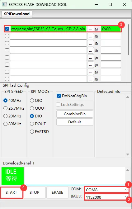
The following uses flashing the ESP32-S3-Touch-LCD-2.8 factory firmware as an example. The same steps apply when flashing other firmware.
Download and extract Espressif's official Flash Download Tool (Download)
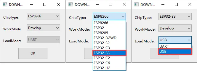
Run flash_download_tool_3.9.7.exe and select the development board's MCU and download interface, such as ESP32-S3 and USB (most devices use USB; refer to the product's hardware design for the correct interface).
Parameter settings
- Select the COM port for the development board
- Set BAUD to the maximum value, 1152000
- Click the "..." button in the row, select the bin file provided by Waveshare, manually enter the flash address given at the top of this page in the field to its right, and select the leftmost checkbox in the row
- Click START to begin flashing
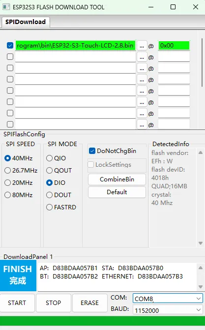
Wait for flashing to complete (this may take some time; please be patient)
Press the reset button and verify the result
Resources
1. Hardware Resources
Development Board Design File
2. Technical Manuals
ESP32-P4 Chip Official Manuals
3. Example Programs
Support
Monday-Friday (9:30-6:30) Saturday (9:30-5:30)
Email: services01@spotpear.com