- sales/support
Google Chat:---
- sales
+86-0755-88291180
- sales01
sales@spotpear.com
- sales02
dragon_manager@163.com
- support
tech-support@spotpear.com
- CEO-Complaints
zhoujie@spotpear.com
- sales/support
WhatsApp:13246739196
- HOME
- >
- PRODUCTS
- >
- Raspberry Pi HATs
- >
- PRI CM4
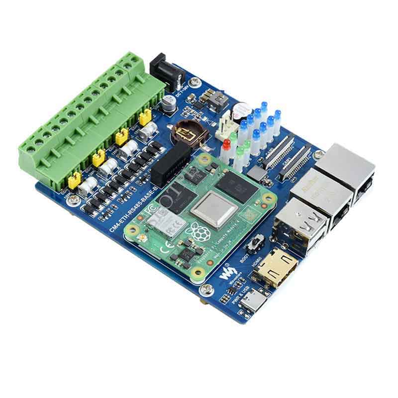
Raspberry Pi CM4 Compute module 4 Dual network port four way isolation type Gigabit Ethernet USB 2.0
$56.89
Brand:Spotpear
SKU:0101432
Date:2022-02-18 11:03
Part Number:
Raspberry Pi CM4 Compute module 4 Dual network port four-way isolation type Gigabit Ethernet USB 2.0
CM4-ETH-RS485-BASE-B
For Raspberry Pi Compute Module 4 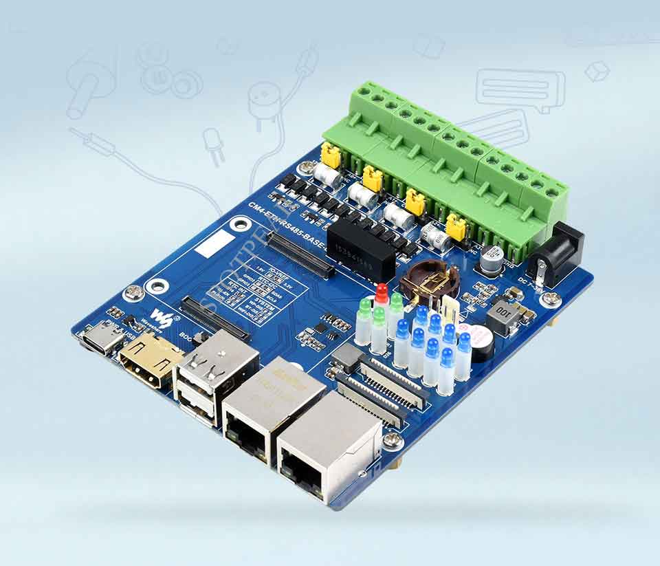
Features At A Glance
- CM4 : for all versions of Compute Module 4
- Networking: Gigabit Ethernet RJ45 port × 1; Fast Ethernet RJ45 port × 1
- USB: USB 2.0 Type A port × 2
- Connector: Isolated RS485 × 4; Power Terminal × 1
- Camera: MIPI CSI-2 interface × 2 (15pin 1.0mm FPC connector)
- Video: HDMI interface × 1, support 4K 30fps output
- Real Time Clock: with battery interface and ability to wake up Compute Module 4
- Storage: Onboard Micro SD card slot (for versions without eMMC)
- Fan: adjustable speed, 5V
- Indicator light: power indicator × 1, CM4 status indicator × 1, user-defined indicator × 2, RS485 communication indicator × 8
- Power input: 7-36V
- Dimensions: 93.6 × 108.8mm
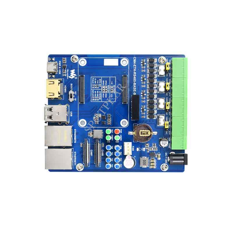
Connect to Compute Module 4 motherboard
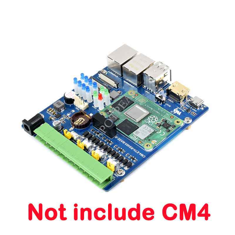
Onboard standard CM4 connector, Supports access to Compute Module 4 Lite/eMMC series motherboards 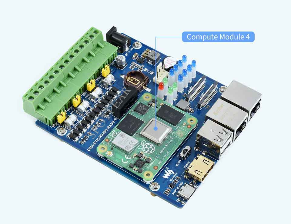
More rich interfaces
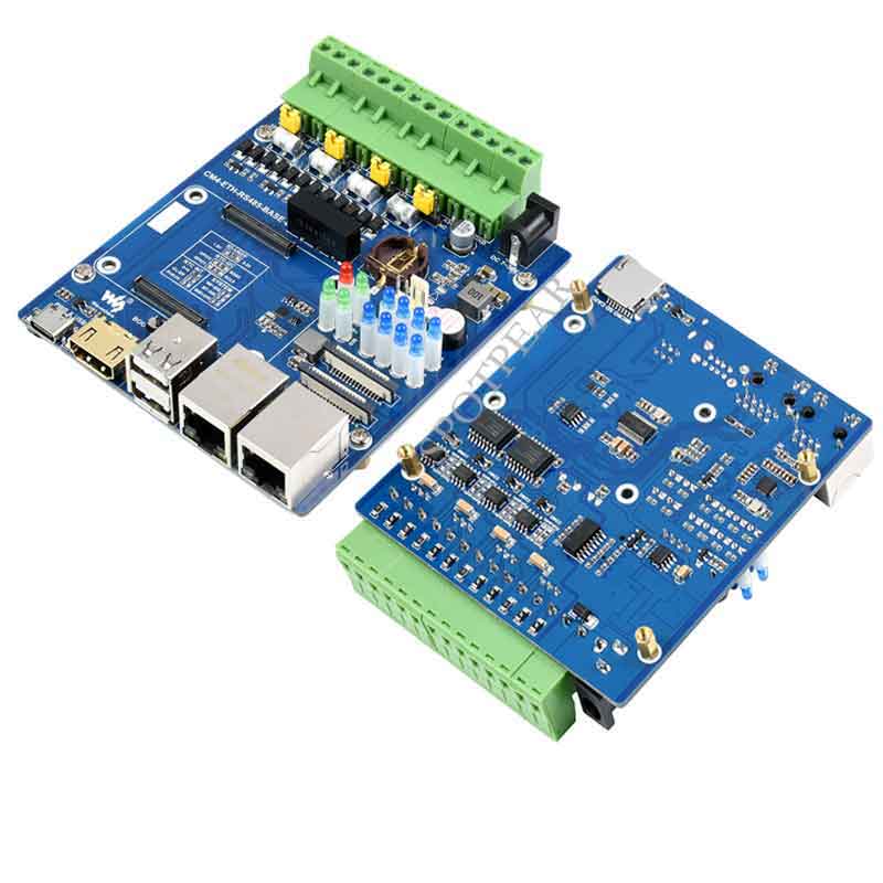
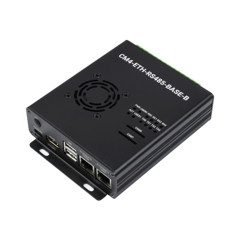
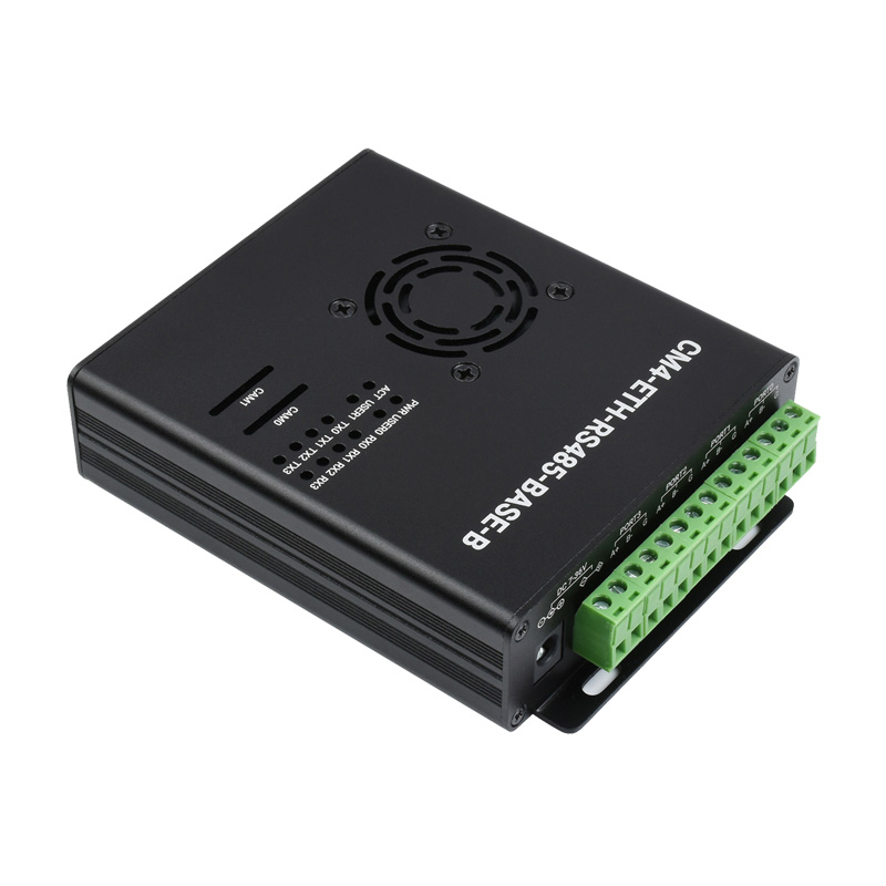
Equipped with dual network ports/RS485/CSI/FAN/HDMI/Micro SD/USB and other interfaces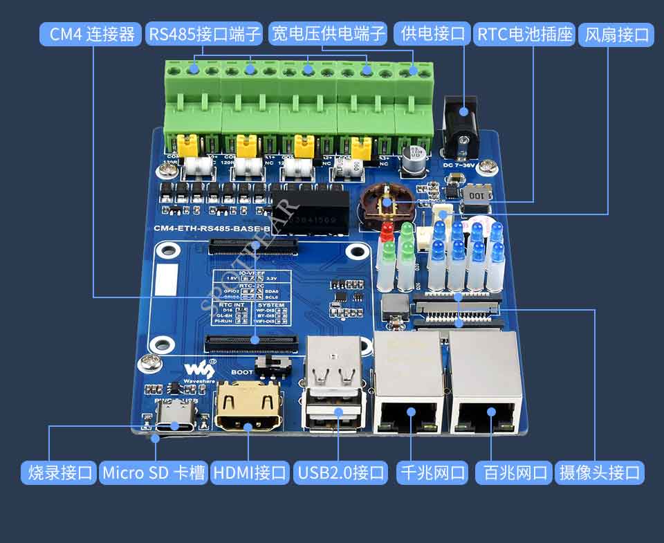
Application example
Raspberry Pi application or other industrial applications for multi-channel RS485 communication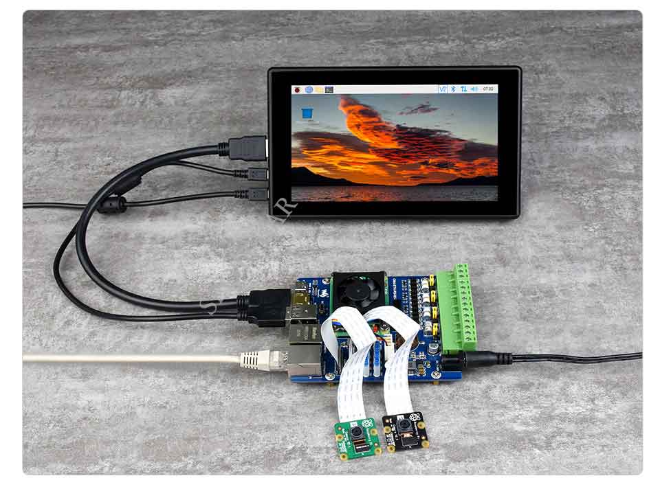
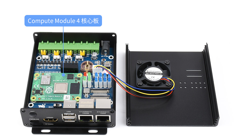
What's On Board
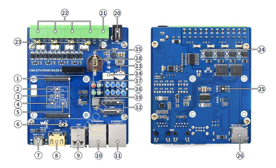

- CM4 connector
Available for all editions of Compute Module 4 - IO-VREF
Select GPIO logic voltage, selectable 3.3V (default) or 1.8V - RTC-I2C: I2C bus selection for RTC
Optional SDA0 & SCL0 (default) or GPIO2 & GPIO3 - RTC INT: RTC interrupt pin select
D16: Use GPIO16 to receive interrupt signal when RTC generates interrupt (default)
GL-EN: CM4 is powered off when RTC generates an interrupt
PI-RUN: CM4 restarts when RTC generates an interrupt - SYSTEM: System function
WP-DIS: Prevent EEPROM from being overwritten
BT-DIS: Disable bluetooth function, only works on CM4 version with antenna
WIFI-DIS: Disable WiFi function, only valid for CM4 version with - BOOT switch
ON: Boot to USB Tpye-C interface
OFF: Boot to eMMC or Micro SD card - PWR & USB
When the BOOT switch is "ON", it can be used as a programming port and a power supply interface
When the BOOT switch is "OFF", it is only used as a power supply interface - HDMI0
HDMI display interface, support 4K 30fps output
- USB
Two-way USB2.0 interface, support USB device insertion - ETHERNET0
CM4 native Gigabit RJ45 Ethernet port - ETHERNET1
USB expansion 100M Ethernet port - CAM0 & CAM1
Two MIPI CSI camera interfaces - Buzzer
GPIO22 control - FAN
Four-wire fan interface, only supports 5V fans, PWM speed regulation (GPIO18 control, no speed measurement) - RTC battery interface
Can be connected to CR2032 coin cell battery - RS485 transceiver indicator
TXn: Transmit information indicator for channel n
RXn: Receive information indicator for channel n - User LED light
USER0: GPIO20 control
USER1: GPIO26 control - PWR
Raspberry Pi power indicator - ACT
Raspberry Pi working status indicator - DC 7~36V
DC DC power supply interface - Power supply terminal
DC DC power supply terminal, support 7~36V wide voltage input - RS485 terminal
Four isolated RS485 interfaces, pitch 5.08mm - Jumper cap
Optional 120R Balance Resistor Jumper Cap - RS485 mode switch
Full-auto: automatic mode, the program operation is simple, the load capacity is weak
Semi-auto: semi-automatic mode, need to manually switch the transceiver mode, high reliability, strong load capacity - Encryption chip
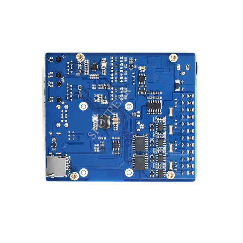
ATSHA204 encryption chip, which can perform multiple encryption to ensure data security and reliability - Micro SD card slot
For access to Micro SD card with system to start Compute Module 4 Lite
Outline Dimensions
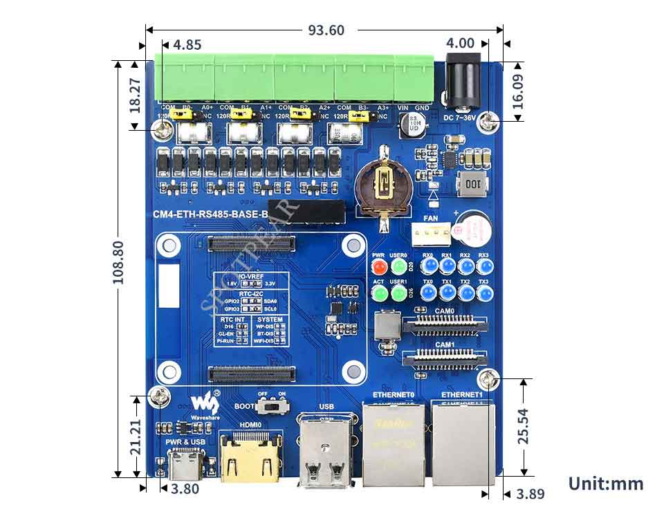
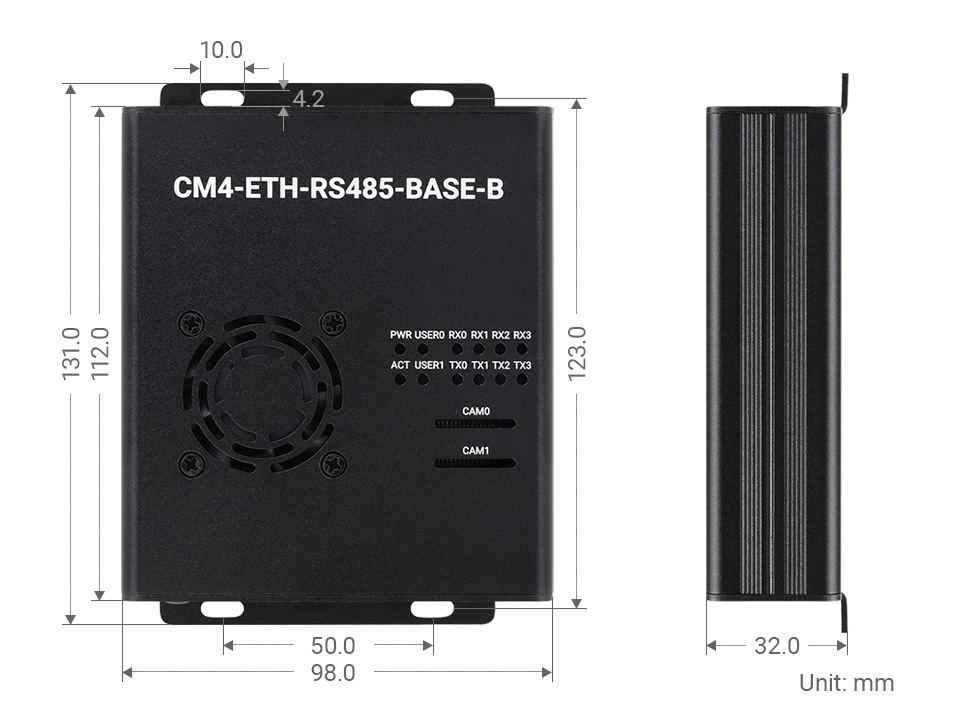
TAG:
Sipeed Lichee Nano LicheePi F1C100s LicheePi
Serial UART Bus Servo ST3215 30KG.CM/19.5KG.CM Magnetic Encoder 360° High Precision And Large Torque
Raspberry Pi 5 Rainbow Acrylic Case Colorful Translucent Acrylic Case Supports Installing Official Active Cooler
Raspberry Pi Pico 1.54inch LCD display 240×240 IPS 1.54 inch screen
VisionFive2
Raspberry Pi 5 PCIe USB UART HAT RS485 ISO TTL RS232 MPUUART
Raspberry Pi
Raspberry Pi 5 PCIe WIFI7
SC3336-3MP-Camera-B
ESP32-S3 Round Screen
Electronic EYE 0.71inch Round Double LCD Display Screen Arduino Raspberry Pi ESP32 Pico STM32
Sipeed NanoKVM-USB
SpotPear
Raspberry Pi USB Camera 5MP OS05A10 Distortion-Free USB 2.0 For Jeston RDK
ESP32 S3 display
LuckFox SC3336
Raspberry Pi DSI LCD
ESP32 P4 Development Board WIFI6 3.4 inch LCD Round Display 3.4inch TouchScreen 800×800 Dual Microphones
Raspberry Pi 3G 4G LTE Mini PCIe Samsung ARTIK Rock64 Asus Tinker Latte Panda
ESP32 C3
Forum:


