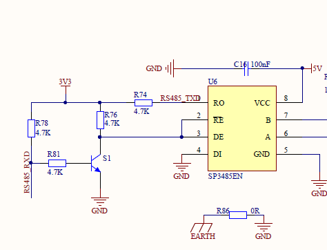
Does anyone know how the the RS485 driver IC circuit (U6) works on the Waveshare ESP32-S3-Touch-LCD-7 PCB?
The UART TX pin from ESP32 is connected to RO (receiver output). So what prevents damage from connecting two outputs together?
Google Chat:---
+86-0755-88291180
sales@spotpear.com
dragon_manager@163.com
tech-support@spotpear.com
zhoujie@spotpear.com
WhatsApp:13246739196
WhatsApp:13424403025
Does anyone know how the the RS485 driver IC circuit (U6) works on the Waveshare ESP32-S3-Touch-LCD-7 PCB?
The UART TX pin from ESP32 is connected to RO (receiver output). So what prevents damage from connecting two outputs together?

SP3485EN is a half-duplex RS485 transceiver, which can either operate in transmitter mode or receiver mode at the same time; it cannot perform both simultaneously. The switching is controlled by the chip's DE/RE pin.
In receiver mode: the RO pin becomes an active output, and it sends data from the bus to the ESP32. The software must configure the UART TX pin as input mode to receive data from RO.
In transmitter mode: the RO pin is in a high-impedance state. At this time, the UART TX pin of the ESP32 is an output pin that sends data to the DI pin of U6. The RO pin appears as if it does not exist, so there is no conflict between the two outputs.
report
I am having trouble to have the RS485 working. I can send data, but cannot receive anything...I checked the pins, are ok, but, the sample software to receive data by rs485 and send the same data by rs485 is not working...I spent some hours to debug, but not found the problem...To send ok, to receive not ok...Could please someone give some support about it ?
report
I have the same problem with the ESP32-S3-Touch-LCD-5B. Using the example RS485_Test, it transmits ok but doesn't receive. What is missing from the example to get this to work?
report
@SpotPearGuest2d69c I got the following reply from Waveshare support and using the arduinoesp32 v3.1.0 the test app works and I can receive data.
The reason it didn't work originally because the GPIO43/44 pins used by the RS485 were locked by the JTAG eFuse and no matter what I did I couldn't bypass that. This was obviously fixed in the specific versions they recommened to be used.
report
@SpotPearGueste0743 I have to get another (fixed )hardware? or the fix is available with the driver or diferent setting?
report