- sales/support
Google Chat: zj734465502@gmail.com
- sales
+86-0755-88291180
- sales01
sales01@spotpear.com
- sales02
dragon_manager@163.com
- support
services01@spotpear.com
- CEO-Complaints
manager01@spotpear.com
- sales/support
WhatsApp:13246739196
- HOME
- >
- PRODUCTS
- >
- ESP32 Series
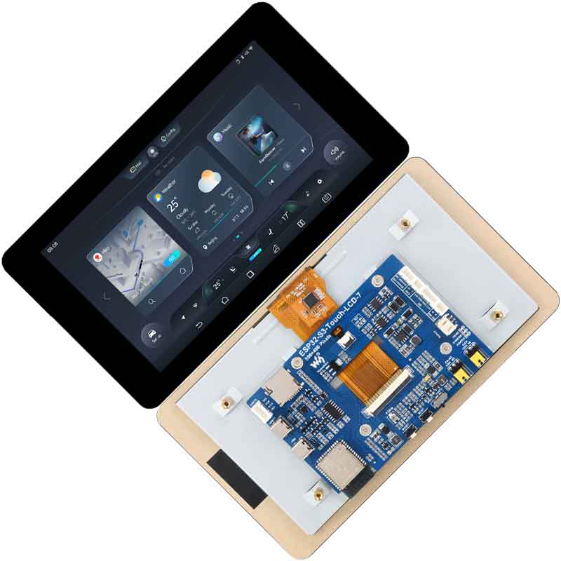
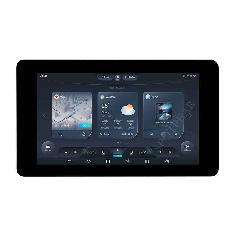
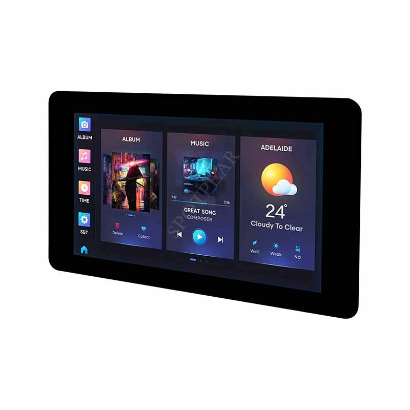
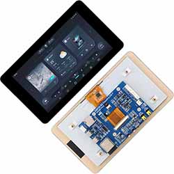
ESP32-S3 7inch LCD Display TouchScreen 800×480 WiFi Bluetooth CAN RS485 Sensor
$34.9
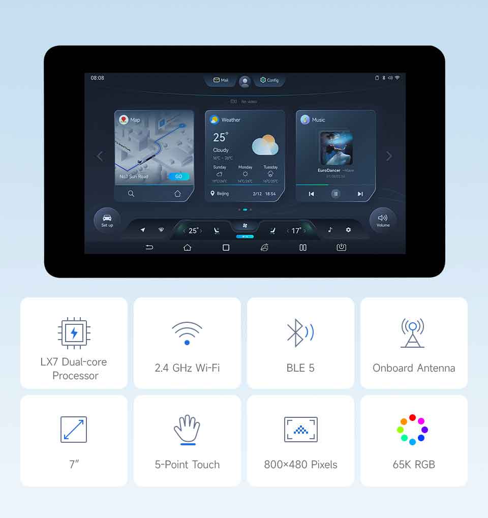
ESP32-S3 7inch Capacitive Touch Display Development Board, ESP32 With Display, 800×480, 5-Point Touch, 32-Bit LX7 Dual-Core Processor, Up To 240MHz Frequency, Supports WiFi & Bluetooth, With Onboard Antenna
ESP32 Display Recommend
】Product Details
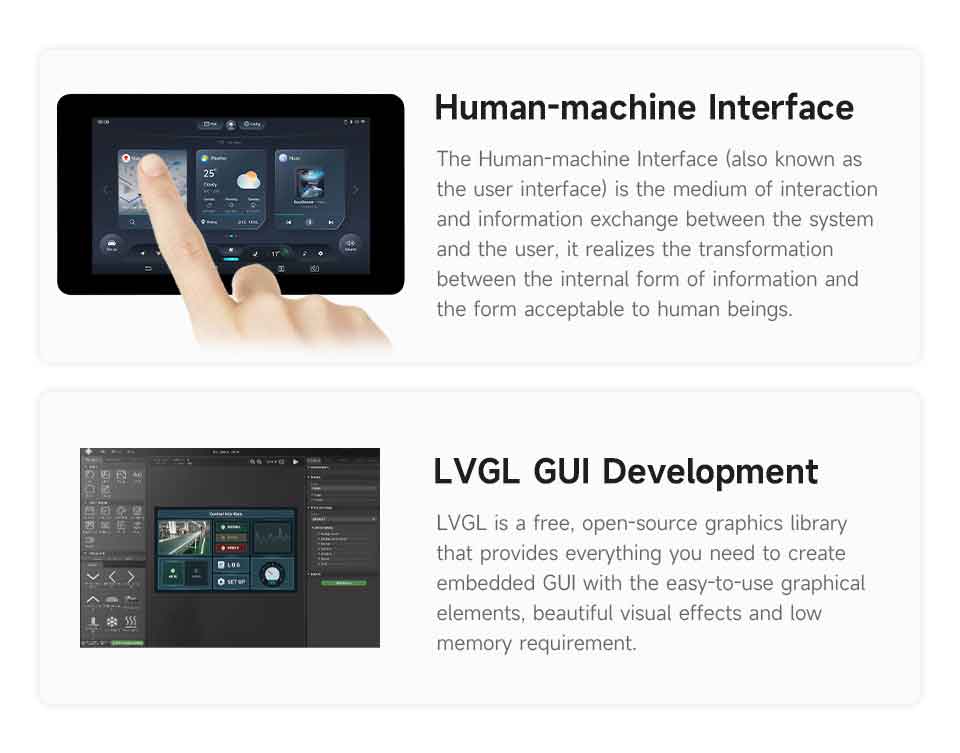
Integrates RGB Interface LCD With 5-Point Capacitive Touch, Multiple Peripheral Interfaces
】Features
ESP32-S3-Touch-LCD-7 is a microcontroller development board with 2.4GHz WiFi and BLE 5 support, integrates high-capacity Flash and PSRAM. Onboard 7inch capacitive touch screen can smoothly run GUI programs such as LVGL. Combined with various peripheral interfaces, suitable for the quick development of the HMI and other ESP32-S3 applications
[] Equipped with Xtensa 32-bit LX7 dual-core processor, up to 240MHz main frequency
[] Supports 2.4GHz Wi-Fi (802.11 b/g/n) and Bluetooth 5 (LE), with onboard antenna
[] Built in 512KB of SRAM and 384KB ROM, with onboard 8MB PSRAM and 8MB Flash
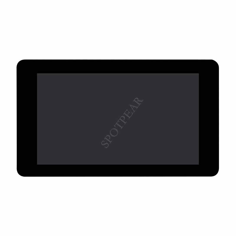
[] Onboard 7inch capacitive touch display, 800×480 resolution, 65K color
[] Supports capacitive touch control via I2C interface, 5-point touch with interrupt support
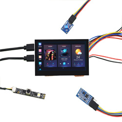
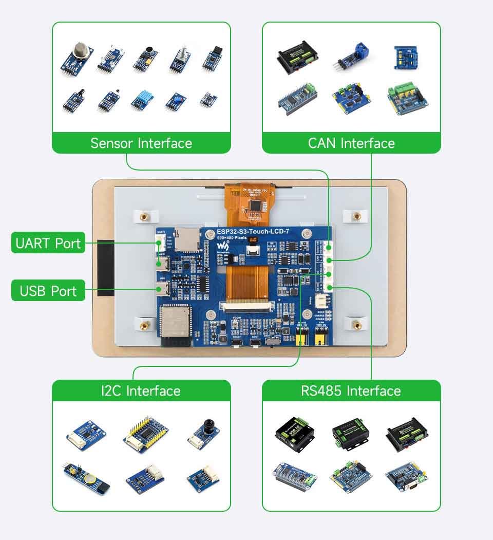
[] Onboard CAN, RS485, I2C interface and TF card slot, integrates full-speed USB port
[] Supports flexible clock, module power supply independent setting, and other control to realize low power consumption in different scenarios
Application Scenarios
Supports Multiple Peripherals
Supports The Expansion Of Multiple Peripherals Via Sensor, CAN, RS485, And I2C Interfaces
Application Example
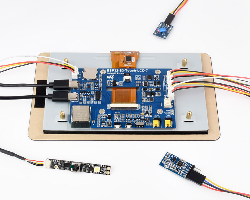
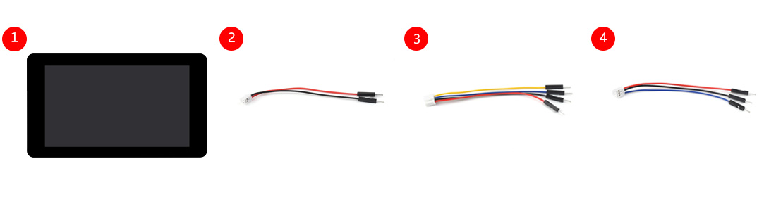
for reference only, please refer to the Package Content for the detailed part list
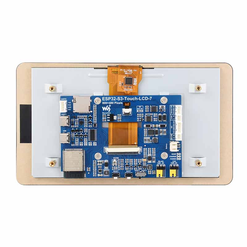
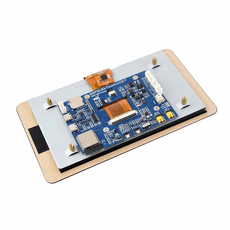
】What's On Board
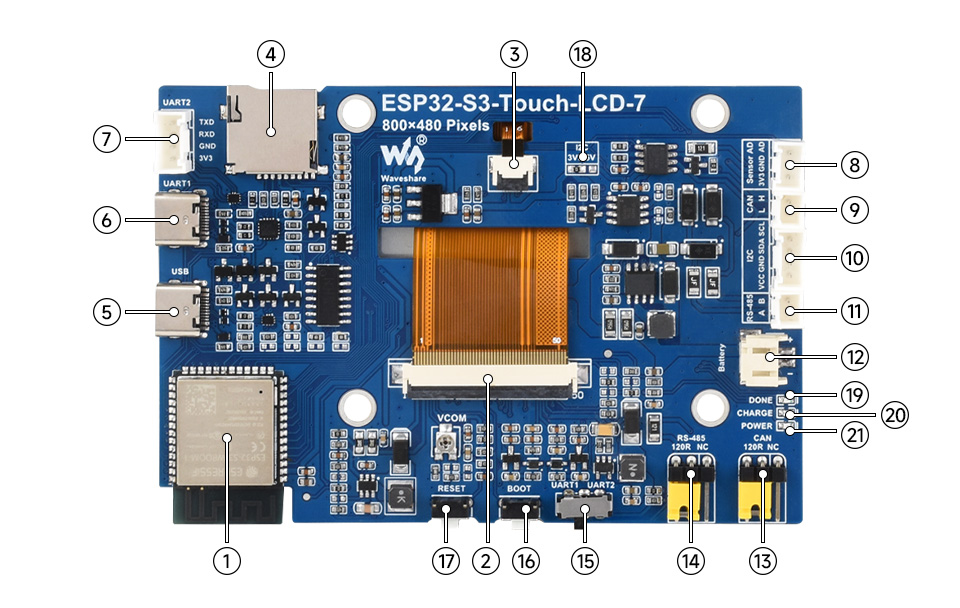
1)ESP32-S3N8R8
The SoC with WiFi and Bluetooth, up to 240MHz operating frequency, integrated 8MB PSRAM and Flash
2)7inch display panel connector
3)Touch panel connector
4)TF card slot
5)USB Type-C port
6)UART1 Port
USB TO UART Type-C port
7)UART2 connector
UART1 and UART2 are the same UART, selected by switch
8)Sensor header
9)CAN header
10)I2C header
11)RS485 header
12)3.7V single lithium battery PH2.0 header
13)CAN terminal resistor selection
14)RS485 terminal resistor selection
15)UART selection
select UART1 or UART2
16)BOOT button
Press and hold while powering on for program burning
17)RESET button
I2C level selection
18)3.3V / 5V
19)DONE
Lithium battery charging completed indicator
20)CHG
Lithium battery charging indicator
21)PWR
Power supply indicator
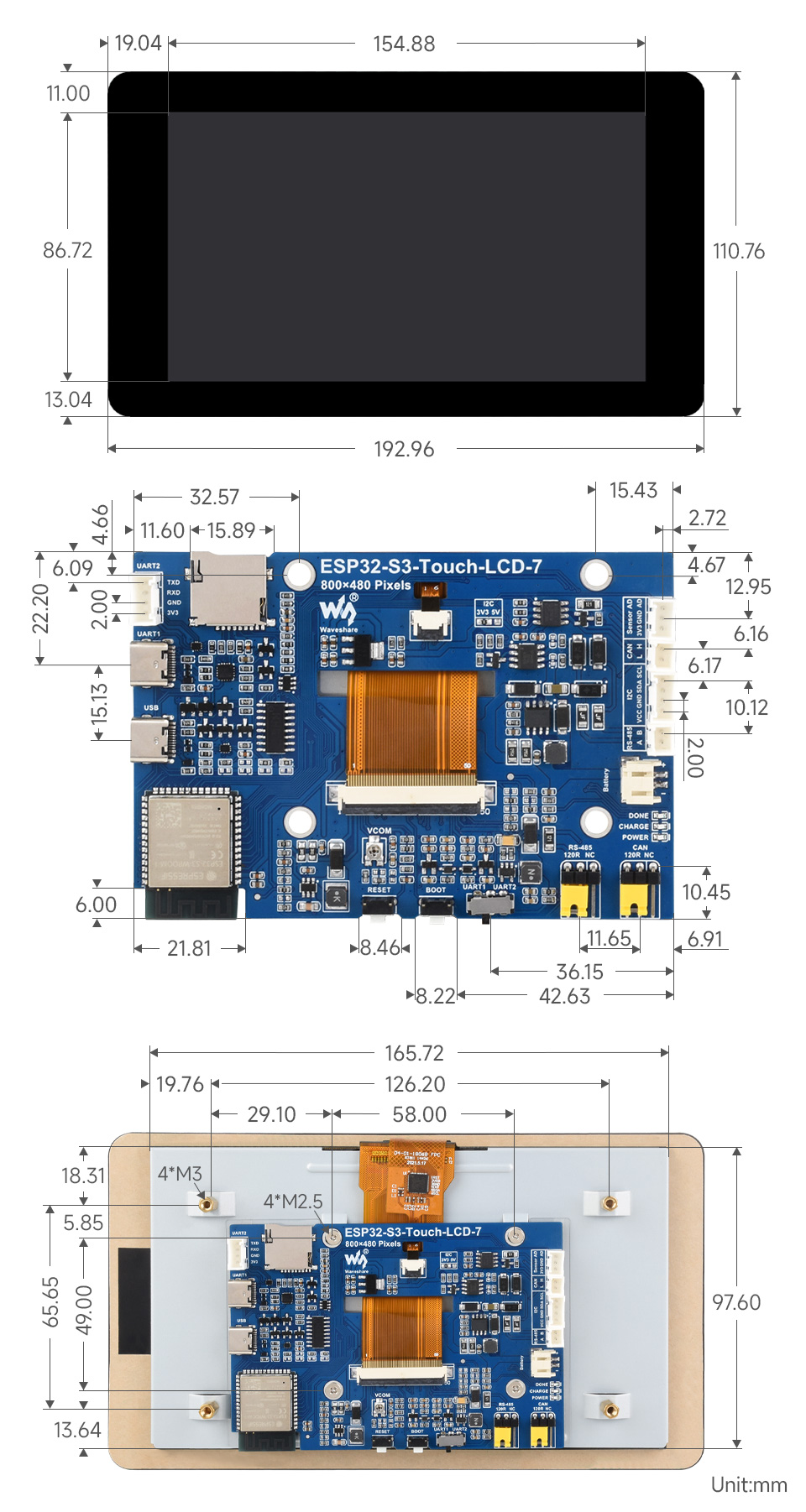
】Outline Dimensions