


- sales/support
Google Chat:---
- sales
+86-0755-88291180
- sales01
sales@spotpear.com
- sales02
dragon_manager@163.com
- support
tech-support@spotpear.com
- CEO-Complaints
zhoujie@spotpear.com
- Only Tech-Support
WhatsApp:13246739196
- Purchase/Shipping/Refund
WhatsApp:13424403025
- HOME
- >
- ARTICLES
- >
- Common Moudle
- >
- Sensors
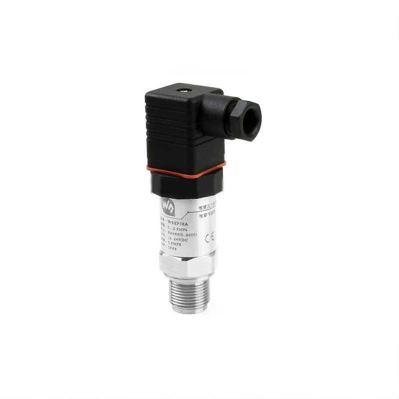
Sensors WSSP08A User Guide
Industrial 2.5MPa Pressure Transmitter, Grade-A Diffused Silicon Transducer, RS485 Bus, Hydraulic / Barometric / Oil Pressure Sensor
Contents
[hide]Features
- Digital output, via RS485 (standard Modbus-RTU protocol)
- Film isolation technology, features corrosion-resistant and obstruction-proof, effectively extend the instrument lifespan
- Integrated chip, small size, easy installation, and wide range input voltage
- IP65 protection rate,cut-off frequency design, strong anti-interference capability
- Protections including current limited, voltage limited, reverse proof (limited output current)
- Measurement accuracy up to 0.5% FS
Specification
- Measured Medium:Liquid, gas (compatible with contact material)
- Accuracy: 0.5%FS
- Overload: 200% full range
- Full weight: 190±5g
- Shock resistant: 10g (20~2000HZ)
- Stability: ±0.2% FS/year
- Pressure range: 0~2.5MPa gauge pressure
- Protection rating: IP65
- Power supply: 12~24V DC
- TEMP.Comprensation: --10~70℃
- TEMP.Drift:±0.2% FS/℃ (in compensation range)
- Output signal: RS485 (standard Modbus-RTU protocol)
- Operating environment:
- Medium temperature: -40~85℃
- Ambient temperature: -40~85℃
- Ambient humidity: 0%~95% RH (non-condensing, non-frosting)
- Material:
- Film: 316L stainless steel (contacted)
- Intermediate junction: 304 stainless steel (contacted)
- Shell: 304 stainless steel
- Sealing: Buna-N rubber (contacted)
- Hirschmann connector: ABS engineering plastics
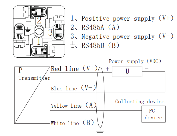
Interface
WSSP08A uses a standard RS485 interface. RS485 supports multi-point, duplex communication, it allows multiple transmitters to be connected o the same bus.
| Hesman interface | |
| 1 | V+(12V~26V) |
| 2 | A |
| 3 | V-(GND) |
| 4( | B |
Communication Protocol
Modbus protocol is a universal language used in industrial electronic controllers. Modbus supports communication to and from multiple devices connected to the same cable or Ethernet network, it has become a standard communication protocol. With the Modbus, control equipment produced by different manufactures can be connected to the sam industrial network for centralized monitoring. The protocol defines a message structure, which can be recognized and used by the controller through any network. It describes the process of a controller requesting access to other devices, how to respond to requests from other devices, and how to detect and record errors. It has formulated a common format for the structure and content of the message domain.
Advantage of Modbus: (1)It is a standard protocol, open-sources, and free to use. (2)Modbus protocol support RS-232, RS-485 bus, and so on. (3)The format of Modbus is simple and easy to use.
Modbus parameters of WSSP08A (the device address is default 01)
This sensor is compatible with Modbus RTU. The RS485 port is half-duplex.
a) Output signal: RS485 (Communication distance is up to 1000m. Support multi-connect 32 devices)
b) Standard Modbus-RTU protocol (03: Read data; 06: Write setting data)<br /? c) Data format: 9600, N, 8, 1
d) Measure range: 0-X(MPa, kPa...)
e) Accuracy: 0.05%
f) Output data: 0...2000(range is customizable)
g) Response frequency: ≤5Hz
h) Response speed: ≥10ms
0x03: Read data (HEX)

- Examples 1
- Read sensor
The device address of 0-1.6Mpa sensor is 0x01, that is [Address]=01 (The Address range 01-254)
CRC0=84 and CRC1=0a, then the commands will be:
Command: 01 03 00 00 00 01 84 0A
Response: 01 03 02 02 AC B9 59
Convert 02AC to DEC, you will get the data 684;
Because the data range is 0-2000, related to the pressure range 0-1.6Mpa, the pressure read is P = 1.6*684/2000=0.5472MPa
The formula: (The maximum range - the minimum range) /2000 * Current data + minumin ranage = current pressure.
- Examples 2
- Read device address (This command only work for a single sensor)
Command: FF 03 00 0F 00 01 A1 D7
Response: FF 03 02 00 01 50 50
That is: The device address is 01
0x06: Write data (HEX)

- Examples
- Modify the device address from 01 to 09
Command: 01 06 00 0F 00 09 79 CF
Response: 01 06 00 0F 00 09 79 CD
The modification will be valid without a restart.
Connection
Pull out the terminal block which is inside the casing of the plug to connect the wire, wiring steps areas shown in the following figure.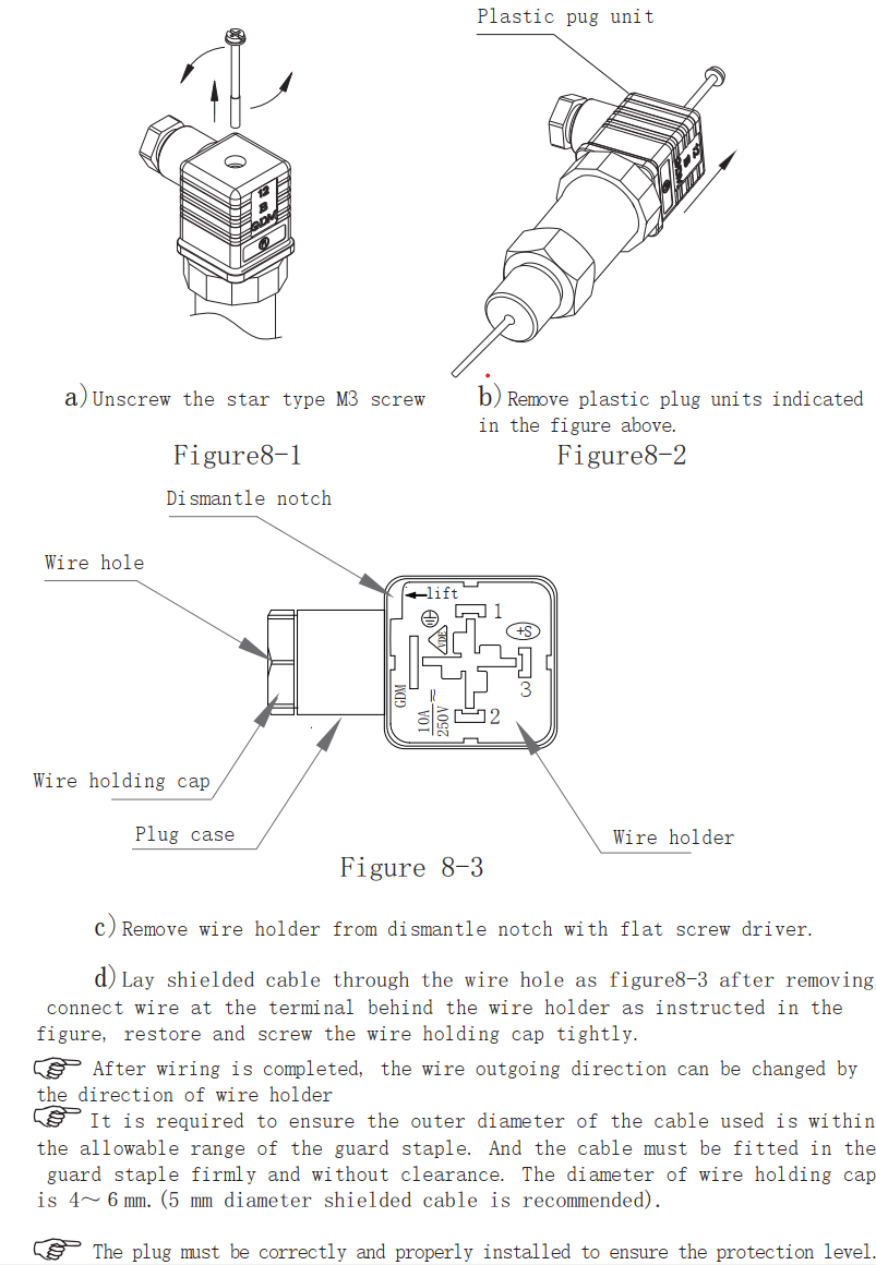
Wiring diagram